S&S Cycle TC3 Oil Pump Instruction Sheet
- Category
- Engine
- Type
- Instruction Sheet

S&S
® Cycle, Inc.
14025 Cty Hwy G
Viola, Wisconsin 54664
Phone: 608-627-1497
Technical Service Email: sstech@sscycle.com
Website: www.sscycle.com
Installation Instructions: S&S TC3 Oil Pumps
for 1999-up Harley-Davidson® Big Twin Engines
IMPORTANT NOTICE:
Statements in this instruction sheet preceded by the following words are
of special signicance.
WARNING
Means there is the possibility of injury to yourself or others.
CAUTION
Means there is the possibility of damage to the part or motorcycle.
NOTE
Other information of particular importance has been placed in italic type.
S&S recommends you take special notice of these items.
WARRANTY:
All S&S parts are guaranteed to the original purchaser to be free of
manufacturing defects in materials and workmanship for a period of twelve
(12) months from the date of purchase. Merchandise that fails to conform
to these conditions will be repaired or replaced at S&S’ option if the parts
are returned to us by the purchaser within the 12 month warranty period or
within 10 days thereafter.
In the event warranty service is required, the original purchaser must call or
write S&S immediately with the problem. Some problems can be rectied
by a telephone call and need no further course of action.
A part that is suspect of being defective must not be replaced by a Dealer
without prior authorization from S&S. If it is deemed necessary for S&S
to make an evaluation to determine whether the part was defective, a
return authorization number must be obtained from S&S. The parts must
be packaged properly so as to not cause further damage and be returned
prepaid to S&S with a copy of the original invoice of purchase and a detailed
letter outlining the nature of the problem, how the part was used and the
circumstances at the time of failure. If after an evaluation has been made by
S&S and the part was found to be defective, repair, replacement, or refund
will be granted.
ADDITIONAL WARRANTY PROVISIONS:
(1) S&S shall have no obligation in the event an S&S part is modied by any
other person or organization.
(2) S&S shall have no obligation if an S&S part becomes defective in whole
or in part as a result of improper installation, improper maintenance,
improper use, abnormal operation, or any other misuse or mistreatment
of the S&S part.
(3) S&S shall not be liable for any consequential or incidental damages
resulting from the failure of an S&S part, the breach of any warranties, the
failure to deliver, delay in delivery, delivery in non-conforming condition,
or for any other breach of contract or duty between S&S and a customer.
(4) S&S parts are designed exclusively for use in Harley-Davidson® and
other American v-twin motorcycles. S&S shall have no warranty or liability
obligation if an S&S part is used in any other application.
SAFE INSTALLATION AND OPERATION RULES:
Before installing your new S&S part it is your responsibility to read and
follow the installation and maintenance procedures in these instructions
and follow the basic rules below for your personal safety.
• Gasoline is extremely ammable and explosive under certain conditions
and toxic when breathed. Do not smoke. Perform installation in a well
ventilated area away from open ames or sparks.
• If motorcycle has been running, wait until engine and exhaust pipes
have cooled down to avoid getting burned before performing any
installation steps.
• Before performing any installation steps disconnect battery to
eliminate potential sparks and inadvertent engagement of starter
while working on electrical components.
• Read instructions thoroughly and carefully so all procedures are
completely understood before performing any installation steps.
Contact S&S with any questions you may have if any steps are unclear or
any abnormalities occur during installation or operation of motorcycle
with a S&S part on it.
• Consult an appropriate service manual for your motorcycle for correct
disassembly and reassembly procedures for any parts that need to be
removed to facilitate installation.
• Use good judgment when performing installation and operating
motorcycle. Good judgment begins with a clear head. Don’t let
alcohol, drugs, or fatigue impair your judgment. Start installation
when you are fresh.
• Be sure all federal, state, and local laws are obeyed with the installation.
• For optimum performance and safety and to minimize potential
damage to carb or other components, use all mounting hardware that
is provided and follow all installation instructions.
• Motorcycle exhaust fumes are toxic and poisonous and must not be
breathed. Run motorcycle in a well ventilated area where fumes can
dissipate.
DISCLAIMER:
These parts are designed as service repair components for the maintenance
of Harley-Davidson® motorcycle engines. They are intended to provide the
same t and function as the stock components that they replace.
It is the sole and exclusive responsibility of the user to determine the
suitability of the product for his or her use, and the user shall assume all
legal, personal injury risk and liability and all other obligations, duties, and
risks associated therewith.
The words Harley®, Harley-Davidson®, H-D®, Sportster®, Evolution®, and all
H-D part numbers and model designations are used in reference only. S&S
Cycle is not associated with Harley-Davidson, Inc.
Instruction 510-0347
06.14.2023
© 2015–2020
by S&S® Cycle, Inc.
All rights reserved.
Printed in the U.S.A.

2
INSTALLATION INSTRUCTIONS FOR THE FOLLOWING S&S PART
NUMBERS
310-0640, TC3 Oil Pump Kit 1999-2006 except 06 Dyna®.
310-0641 TC3 Oil Pump Kit 2007–Up BT and 2006 Dyna®.
NOTES:
• Installation of S&S oil pump requires the use of special tools and
repair manuals for the model bike you will be doing the work on.
Attempting the installation without the proper tools and manuals
will be dicult. Damage can result which will not be covered under
warranty.
• Possible failure may result if thread locking compound is not applied
to the cam drive sprocket ange bolts. Always prepare threads
according to the instructions on the container.
• All reference to Harley-Davidson® part numbers is for identication
purposes only. We in no way are implying that any of S&S Cycle’s
products are original equipment parts or that they are equivalent to
the corresponding Harley-Davidson® part numbers
Information below is for all installations. Steps 1-8 below must be
followed.
1. Refer to proper H-D® manual for the model of bike you will be
working on for the removal of existing oil pump.
2. Once you have successfully removed the cam plate and oil pump
from the motor inspect ywheel for pinion shaft run out. Refer to
manual for proper inspection procedure.
3. If you will be reusing your existing cam plate. Wash cam plate
and inspect bearing bores / bushing bores for size, refer to the
manufacturers specications for service wear limits on these
bores, replace bearings as necessary. It is easier to replace the
bearings now while the engine is apart. Inspect the pump
mating surface for scoring; if the surface where the pump gears
run against the plate has been scored this could adversely aect
oil pressure.
NOTE: If your cam plate has non serviceable oil galley plugs and has
been exposed to debris from previous engine malfunctions or other
foreign material, it is almost impossible to eectively clean the passages.
A new cam plate may be a better option.
4. It is also a good idea to clean and inspect the pressure relief valve
of the cam support plate if you will be reusing your existing one.
Refer to the manual for proper removal of the pressure relief
valve. The pressure relief valve should move freely in the bore.
5. Inspect or replace chain tensioners as needed refer to H-D®
manual for service wear limits.
6. Inspect inner cam bearings, now is the time to replace these
bearings while the engine is apart. Refer to manual for proper
procedure and proper tools to use when replacing these
bearings. NOTE: Full compliment bearings are recommended.
7. Clean and ush your oil tank and oil lines. Any foreign matter
that has accumulated in your oil tank will be sucked through
your new oil pump. Oil pans with riveted-in bae can be very
hard to clean, it is very important to remove all debris from the
pan. Also, when installing the S&S oil pump, the oil lter should
be changed.
S&S Oil pump installation instructions
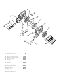
8. Remove pump from package and inspect pump for shipping
damage. If there is any damage contact S&S immediately. Make
sure pump has all parts shown in assembly drawing. Last page
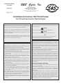
9. Make sure you have the proper pump for the style of cam plate
you will be using. Late style and early style pumps have dierent
bolt patterns. One screw located in the upper right corner when
looking at the front of the pump is located dierently. An early
pump can’t be used on a late cam plate and a late pump will not t
on an early cam plate. See Figure 1 below.
NOTE: If using an S&S 1999-’06 style cam plate a 2007-later style oil pump
must be used
10. Disassemble and wash all parts. Check to make sure all plugs have
been installed.
11. We feel it is easiest to assemble pump into motor one piece at a
time.
12. First install scavenge port O-ring in case (do not install O-ring
onto pump). Put some engine oil or assembly lube on the O-ring
to make installing the pump housing easier.
13. Install rear pump housing. Push the housing into the O-ring with
your thumb. Make sure it goes in all the way.
NOTE: The drive ats on these gears are purposely wider than the stock
drive ats. This allows for more freedom of movement. This helps prevent
excessive side loading but still gives plenty of engagement for turning the
rotors.
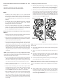
14. Apply assembly lube to inner return gear set, and assemble
inner gear inside outer gear. Align the inner gear with the at
on the pinon shaft and install gear set into inner pump body as
an assembly. Make sure the relief cut side of the inner gear goes
toward the engine See Picture 1.
Early style: Front view Late style: Front view
Early style: Back
view of front half
Late style: Back
view of front half
These holes
dierent locations
Slot
Hole
This hole closer
to the gear on late pump
Figure 1

3
NOTE: Do not mix and match inner and outer gears keep them as sets as
they are shipped in the pump.
15. Install two ⁄" x ¾" dowels into pump housing. See #7 in line
drawing on Page 4.
16. Install divider plate
17. Apply assembly lube to second return gear set. Place gear set into
outer pump body and install outer pump body onto inner pump
body.
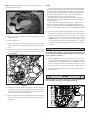
18. Place straight edge across front of cam chest and make sure the
face of the pump does not protrude past the cam chest gasket
surface. Figure 2
19. If pump protrudes past gasket surface check to see that the pump
is installed all the way into the scavenge port O-ring. If this doesn’t
solve the issue and you cannot see any other areas of interference
contact the S&S tech line at 608-627-8324.
20. Apply assembly lube to the .250 wide feed gear set and install into
pump. Be sure this does not protrude past the front face of the
pump body.
Picture 1
This side
toward engine
Figure 2
NOTES
• If using a stock cam support plate with the S&S oil pump we DO NOT
recommend stretching the pressure relief spring to increase oil pressure
as the pump will normally supply plenty of oil pressure. Stretching the
spring may result in overly high oil pressure which could result in leaks
around hoses and or gaskets. Excessive oil pressure causes higher oil
temperatures and uses more power to turn the pump.
• If installing oil pump with the motor in the bike put transmission in
high gear and raise rear wheel o the table so you can turn the engine
over using rear wheel.
• S&S recommends replacing stock spring style hose clamps on oil
cooler lines, where they attach to the lter adaptor, with crimp style
clamps. Spring clamps do not provide adequate clamping force to keep
oil lines secure on the hose nipples under extended high rpm operation.
21. Install cam support plate following the H-D® service manual or
manufacturer’s specic instructions. Apply a small amount of blue
threadlocker to screws that hold the cam plate to crankcase.
Tighten them to 100 in-lb, following the torque sequence shown
in Figure 3 for the cam plate screws (in circles). Apply a small
amount of blue threadlocker to the 4 supplied ¼" 20 x 2" bolts,
install them with the 4 supplied ¼" washers to secure oil pump to
cam plate.
Use threadlocker sparingly on pump screws. Be careful not to get
excess threadlocker between the pump half’s or in the pump gear
bores as damage could occur
22. Refer to Figure 3 for proper torque sequence. While rotating
the engine, alternately tighten bolts 1 and 2 (shown in squares)
until the bolts are snug. Tighten bolts 3 and 4 until they are snug.
Finally, torque the four bolts in the sequence shown in to 100 in-
lbs. This procedure ensures that the oil pump is properly centered
23. Reinstall all remaining components according to the proper HD®
service manual.
Failure of fasteners or parts caused by incorrect installation can
cause extensive damage not covered under warranty
CAUTION
CAUTION
Figure 3
6
1
2
3
4
5
3
2
4
1

1. Oil pump body case return section ...........................NA
2. Oil pump body cam chest return / pressure feed ...............NA
3. Oil pump rotor set, ywheel cavity return ..............310-1092
4. Oil pump rotor set, cam chest cavity return .............310-1048
5. Oil pump rotor set, supply ...........................310-0561
6. Plate, divider ......................................310-0516
7. Dowel Pin, .125 x .750 Hardened Steel ................106-3794
8. Debris screen ......................................310-0546
9. Internal Retaining Ring, .625 .........................500-0860
10. Internal Retaining Ring, 17mm .......................500-0859
11. O-ring, 1.5mm x 14mm, Viton (5 Pack) .................500-0861
12. Oil pump return plug ...............................310-0564
13. Plug, Pipe 1/8" 27 .................................50-8331A
14. O-ring kit .........................................500-0326
15. Screw, Kit, Oil Pump, 1999-Up BT
(¼" 20 x 2" SHCS w/washers) .......................500-0327
-
 1
1
-
 2
2
-
 3
3
-
 4
4


S&S Cycle TC3 Oil Pump Instruction Sheet
- Category
- Engine
- Type
- Instruction Sheet
Ask a question and I''ll find the answer in the document
Finding information in a document is now easier with AI
Related papers
-
S&S Cycle OES Gear Drive Cam Instruction Sheet
-
-
-
-
-
-
-
-
-
