
USER’S MANUAL
WSME-200D
AC/DC TIG
&
MMA
INVERTER WELDING M
ACHINE
Please read the User’s Manual carefully before using the machine.

CONTENTS
IDENTIFYING SAFETY INFORMATION
●The symbols are being used to identify potential risks.
●When seen a safety symbol in the manual, it must be understood
that there is an injury risk and following instructions must be read
carefully to avoid potential risks.
●While welding, keep the third persons and especially the children
away from the work area.
UNDERSTANDING THE SAFETY WARNINGS
Read carefully the manual and the labels and the safety warnings.
●Learn to operate the machine and how to make the controls properly.
●Operate your machine in convenient work areas. Improper modifications
affect the safety of your machine negatively and shorten its lifetime.
SAFETY RULES .......................................................... ........................................................................................... .2
ELECTROMAGNETIC COMPATIBILITY ...................................................................................................... ... . 6
1. TECHNICAL INFORMATIONS ........................................................ .......................................................... ......7
1.1 GENERAL EXPLANATIONS .................................................. ................................................................ ....7
1.2 APPLICATION AREA ........................................................ ..................................................... ............... ......8
1.3 SYMBOL AND MEANING ON DATA PLATE ..................................................................................... ......8
1.4 ENVIRONMENTAL CONDITIONS ....................................................... ...................................................9
2. INSTALLATION ..................................................................................... ..................................................... ......10
2.1 UPON RECEIPT AND CLAIMS........................................................... ..................................................... . .10
2.2 WORK AREA ........................................................................................... .............................................. .. ...10
2.3 INSTALLATION AND USAGE OF THE MACHINE ................................................ .................................10
2.3.1 CONNECT TO POWER SUPPLY,TORCH,WORK-PIECE AND OPERATION CONTROLLING ....11
2.3.2 CONNECT OUTPUT(-) AND OUTPUT(+).......................... ................................. ..............................15
2.3.3 CONNECT THE GAS CYLINDER ............................... ..................................................... .. ....................18
3. USAGE INFORMATION .......................................................................................................................... ... ......19
3.1 ABOUT OVER-HEATING AND OVER CURRENT........................................................................ ... .......19
3.2 ADJUSTING THE GAS FLOW.......................................................................................................... ... .......19
3.3 ARC STARTING FOR TIG WELDING PROCESS... .................... .................... .................... ....................19
3.4 ADJUSTING THE WELDING CURRENT.......................................................................................... ... .....19
4. MAINTENANCE AND TROUBLESHOOTING........................................................................................ ........21
4.1 PERIODIC MAINTENANCE................................................................................................................ ... ....21
4.2 NONPERIODIC MAINTENANCE.................................................................................................... ... ..... ..21
4.3 BASIC TROUBLESHOOTING ..................................................................................................... ... ........ ...22

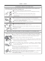
SAFETY RULES
ELECTRICAL SHOCK COULD BE FATAL
Installation procedure must comply with national electricity standards and other relevant regulations and
ensure that installation is performed by qualified persons.
●Wear dry, hole-free insulating gloves and body protection.
●Do not touch electrode with bare hand. Do not wear wet or damaged gloves and body
protection.
●Do not touch live electrical parts.Never touch electrode while in contact
with working surface, ground or another electrode which is connected to
a different machine.
●Protect yourself from electric shock by insulating yourself from work and ground.
Use non-flammable, dry insulating material if possible, or use dry rubber mats, dry wood
or plywood, or other dry insulating material big enough to cover your full area of contact
with the work or ground, and watch for fire.
●Never connect up more than 1 electrodes or wires to the machine.
●Turn off the machine, when not in use .
●Disconnect input plug or power before working on machine.
●Frequently inspect input power cord for damage or bare wiring - repair or replace cord
immediately if damaged.
●Be sure input ground wire is properly connected to a ground terminal in disconnect box or
receptacle.
BREATHING WELDING FUMES CAN BE HAZARDOUS TO YOUR HEALTH
Inhaling fumes and gases over a long period of time, generated during welding is dangerous and forbidden .
●Irritation of the eyes, nose and throat are symptoms of inadequate ventilation.Take
immediate steps to improve ventilation. Do not continue welding if symptoms persist.
●Install a natural or forced air ventilation system in the work area.
●Install an adequate ventilation system in the welding and cutting area, if needed install a
system that can remove the fume and vapor accumulated in the entire work area, to prevent
pollution use adequate filtration in discharge.
●In the event of welding in small, confined places, or welding lead, beryllium, cadmium,
zinc, zinc coated or painted materials; also wear a fresh air supplied respirator in addition
to the above mentioned rules .
●Always have a trained watch-person nearby, while working in small confined places.
Avoid working in such confined places if possible.
●If gas cylinders are grouped in a different area, make sure that it is a well-ventilated area.
When not being used, turn off the cylinder valve .
●Shielding gasses such as argon is denser than air and when being used in confined places,
can be inhaled in place of air, and this is dangerous for your health.
●Do not perform welding operations near chlorinated hydrocarbon vapors produced
by degreasing or painting.
-2-

SAFETY RULES
ARC RAYS CAN BURN EYES AND SKIN
●Use adequate welding helmet with correct shade of filter ( 4 or 13 considering TS EN
379 ) to protect your eyes and face.
●Protect open parts of your body (arms, neck and ears) from arc rays by adequate protective
clothing.
●To protect others by arc rays and hot metals, surround the working area with flame proof
curtains which are higher than eye level and put up warning boards.
FLYING METALS CAN INJURE EYES
●Welding cause sparks and flying metal.
●To prevent injuries wear appropriate safety glasses with side shields even under your welding helmet .
NOISE CAN DAMAGE HEARING
●Noise from certain industrial processes or equipment can damage hearing.
●Wear approved ear protection if noise level is high.
HOT PARTS CAN CAUSE SEVERE BURNS
●Do not touch hot parts.
●Allow cooling time before servicing.
●If needed to hold hot parts, use appropriate tool, insulating gloves and fireproof clothes.
MOVING PARTS CAN CAUSE INJURY
●Keep away from moving parts.
●Keep all doors, panels, and guards closed and secured.
●Wear shoes with metal protection over the fingers.
WORKING IN SMALL AND CONFINED PLACES CAN BE DANGEROUS
●While welding and cutting in small, confined places, always have a trained watch-person nearby.
●Avoid working in such confined places.
-3-

SAFETY RULES
WELDING WIRE MAY CAUSE INJURY
●Do not point the gun toward any part of a human body, other persons or any type of metal when unwinding welding
wire.
●While extracting the wire from the spool by hand, it may spring suddenly and injure you or a nearby person, protect
especially your eyes and face.
●Make sure that there is no one close.
WELDING CAN CAUSE FIRE OR EXPLOSION
●Never weld near flammable material. It may cause fire or explosions.
●Before starting to weld, move flammables away or protect them with flame-proof covers.
●Do not weld on and cut closed tubes or pipes.
●Before welding on closed containers, open and clear them entirely. Welding operations on
these parts must be performed with the utmost caution.
●Never weld containers or pipes containing or which have contained substances that could
give rise to explosions.
Welding equipment warms up so never position them on flammable surfaces.
●Welding sparks can cause fire. For that reason, keep extinguishing means, such as fire
extinguishers, water and sand easy reach.
●Have and maintain security valves, regulators and other valves on the flammable,
explosive and compressed gas circuits in good condition by periodical controls,used for
welding and cutting operations.
FALLING UNIT CAN CAUSE INJURY
Wrong positioned power source or other equipment may cause serious injury to persons or
damage to objects.
●While re-positioning the power source always carry by using the lifting eye. Never pull cable, hose or Gun.
Always carry the gas cylinders separately.
●Before carrying the welding and cutting equipment, disassemble all the connections between and separately carry
the small ones by hand-grips and the big ones by lifting eyes or by using appropriate vehicles like forklifts.
●Install your machine on flat platforms having maximum 10° slope that it does not fall over. Install it on well
ventilated, non-confined places away from the dust, also avoiding the risk of falling caused by cables and hoses.
For gas cylinders not to fall over, attach it to the mobile machine or to the wall with a chain.
●Ensure that operators easily reach the controls and connections on the machine.
-4-

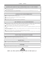
SAFETY RULES
MAINTENANCE MADE BY UNQUALIFIED PERSONS MAY CAUSE INJURIES
●Electrical devices should not be repaired by unqualified persons. Improper repairs can cause serious injuries or even
death during applications.
●The components of the gas circuit works under pressure.The service given by unqualified persons may cause
explosions and operators can be injured seriously.
OVERUSE CAN CAUSE OVERHEATING
●Allow cooling period; follow rated duty cycle.
●Reduce current or reduce duty cycle before starting to weld again.
●Do not block airflow to unit.
●Do not filter airflow to unit without the approval of manufacturer
.
ARC WELDING CAN CAUSE INTERFERENCE
●Electromagnetic energy arising during welding and cutting operations can interfere with sensitive electronic
equipment such as microprocessors, computers, and computer-driven equipment such as robots.
●Be sure all equipment in the welding area is electromagnetically compatible.
●To reduce possible interference, keep weld cables as short as possible, close together, and down low, such as on the
floor.
●To avoid possible EMC damages, locate welding operation as far as possible (100 meters) from any sensitive
electronic equipment.
●Be sure this welding machine is installed and grounded according to this manual.
●If interference still occurs, the user must take extra measures such as moving the welding machine, using shielded
cables, using line filters, or shielding the work area.
STATIC (ESD) CAN DAMAGE PC BOARDS
●Put on grounded wrist strap before handling boards or parts.
●Use proper static-proof bags and boxes to store, move, or ship PC boards.
PROTECTION
●Do not expose the welding machine to rain, protect from water drops and vapour.
●The lifetime determined by Ministry of Industry and Trade is 10 years.
OBEY ALL THE SAFETY RULES STATED IN THE MANUAL!
-5-
LIFETIME

ELECTROMAGNETIC COMPATIBILITY(EMC)
ELECTROMAGNETIC EMISSION
●All electrical equipment generates small amounts of electromagnetic emission due to current transferring in the
equipment. Electrical emission may be transmitted through power lines or radiated through space, similar to a radio
transmitter.When emissions are received by other equipment, electrical interference may result. Electrical emissions
may affect not only welding machines but also many kinds of electrical equipment like radio and TV reception,
numerical controlled machines, telephone systems, computers etc.
●Welding and cutting machines have been designed to work for professional and industrial use; for other applications
to contact the manufacturers.
●The user is responsible for installing and using the equipment according to the manufacturer’s instructions.If
electromagnetic disturbances are detected then it shall be the responsibility of the user of the equipment to resolve
the situation with the technical assistance of the manufacturer. In some cases this remedial action may be as simple
as earthing the welding the welding circuit, in other cases it could involve constructing an electromagnetic screen
enclosing the power source and the work complete with associated input filters.In all cases electromagnetic
disturbances must be reduced to the point where they are no longer trouble some.
●The circuit may or may not be earthed for safety reasons. Changing the earthing arrangements should only be
authorized by a person who is competent to assess whether the changes will increase the risk of injury, e.g. by
allowing parallel welding current return paths which may damage the earth circuits of other equipment.
●Extra precaution may be required when the welding power source is used in a domestic establishment.
●Special measures shall be taken to achieve compliance with welding power source including HF frequency for arc
ignition and stabilizing;it may be required use of shielded cables and in any case to resolve the particular
implementation (e.g. with robot, computer and any other electrical and electronic equipment connected to welding
power source) to call the technical assistance of the manufacturer.
●EMC is Class A according to CISPR II.
ASSESMENT OF THE SURROUNDING AREA
Before installing the welding equipment, the user shall make an assessment of potential electromagnetic
problems in the surrounding area. The following shall be taken into account- if needed arrange the working
hours that not coincide with those.
●Other supply cables, control cables, signaling and telephone cables; above, below and adjacent to the welding
equipment,
●Radio and television transmitters and receivers,
●Computer and other control equipment,
●Safety critical equipment,
●Presence of heart beat regulators, heart cells, hearing devices or etc. nearby,
●Equipment used for calibration or measurement,
●The immunity of other equipment in the environment.
The user shall ensure that other equipment being used in the environment is compatible. This may require
additional protection measures.
METHODS OF REDUCING EMISSIONS
●Welding equipment should be connected to the mains supply according to the manufacturer’s recommendations. Our
welding machines are filtered against emission according to standards. If interference still occurs, it may be necessary
to take additional precautions such as filtering of the mains supply.
●The equipment should be routinely maintained according to the manufacturer’s recommendations.The welding
equipment should not be modified without the approval of manufacturer.
●The welding cables should be kept as short as possible and should be positioned close together, running at or close
to the floor level. Power cables and signal cables should be kept separately.
●Keeping cables in the shape of -8- and taping together reduce emission.
●Connect earth clamp to work-piece as close to the weld as possible. But the user should be control whether this
situation damage to people and equipment or not.
-6-

TECHNICAL INFORMATION
1. TECHNICAL INFORMATIONS
1.1 GENERAL EXPLANATIONS
●WSME-200D welding machine is manufactured with advanced inverter technology. With high-power component IGBT
and by adopting PWM technology.The first inverter convert the DC voltage or current, which is rectified from input AC
voltage or current, to high 20KHz frequency AC voltage or current. As a consequence, the voltage or current is transformed
and rectified in the first inverter. The second inverter convert the output voltage or current of the first inverter to lower
frequency AC welding voltage and current.Therefore, it results the much more small-sized of the power source and lighter
in weight of the inverter welding machine, which rates the performance of welding by 30%. The high frequency oscillation,
which enables the output of the high frequency DC, is employed in the arc-starting system. The features of this product are
as following: stable the welding current output , reliable, completely portable, efficient and low noise generated while
welding is performed.
●Both MMA Pulsed Current TIG and AC/DC TIG welding Process are available for WSME-200D. AC TIG
welding Process is used to weld aluminum(AL),aluminum alloy,Magnesium(Mg),Magnesium alloy etc.
●During the performance of MMA welding, this welding machine is featured with the stability of output, and the
availability of arc force modulation. In case of normal arc input voltage, the stability of welding current output is not
frustrated with variation of arc length, therefore it results in stable performance of welding operation. In case of unavailable
length of arc and low input voltage, welding output current increases while arc voltage decreases, as a consequence, the
length of arc, which is not sufficient, will automatically compensate and the modulation of arc force is accessible. In case
that the input arc voltage is too low to maintain arc, the output of this welding equipment descends steeply, which avoid the
splash generated due to over current input.
●During the performance of AC/DC TIG welding, this welding equipment is featured with the stability of current output
and that the welding current output does not vary with variation of the length of arc.
●Guarantee of maintenance for main engine is one year, excluding other spare parts.
●During the guarantee maintenance period, all maintenance is free of charge, excluding the deliberated damage to this
welding equipment.
●Only qualified technician are authorized to carry out the repairs task of this welding machine in case of machine
fault.
●For WSME-200D,THE MAIN TECHNICAL SPECIFICATIONS or DATA PLATE
-7-

TECHNICAL INFORMATION
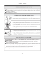
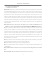
1.2 APPLICATION AREA
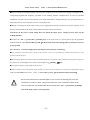
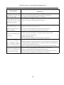
1.3 SYMBOL AND MEANING ON DATA PLATE
single phase input AC power supply, Inverter,DC current or DC/AC current output
MMA welding TIG welding
Output Characteristics of the welding power source is constant current(CC) output for TIG/MMA.
Norm:Application standards,for example, EN 60974-1 or IEC 60974-1.
U1:Rated AC input voltage of the welding power source
I1max:Max. input current.
I1eff:Max. effective input current.
50HZor 60 HZ:Rated frequency of single phase AC power supply .
X: Rated duty cycle.It is the ratio between the load duration time and the full cycle time.
Note1: This ratio is between 0~100%.
Note2: For this standard, one full cycle time is 10min.For example, if the rate is 10%, the loaded time shall be 1 minutes and
rest time shall be 9 minutes.
-8-
●WSME-200D welding machine is single phase,
50/60Hz,constant current(CC) output power sources
especially designed for AC/DC TIG and Pulse
TIG/MMA welding.
●All the controls and adjustment knob of the welding
power sourceare placed on to the front panel for easy
operation.
●Welding Cable , the torch, Earth Cable and gas
hose can be easy connected to the power source.
●Output currents of the WSME-200D welding
machine can be adjusted by some welding current
adjustment knobs .
●WSME-200D is very good selection for medium
thickness metals (up to 0.5~8 mm) welding. It is also a
very good choice for aluminum ,stainless steel and
metals TIG/MMA welding. This machine should be
selected for high duty cycle welding applications.

TECHNICAL INFORMATION
Duty cycle is based on a ten minute period.This means that the arc may be drawn for two minutes out of each ten
minute period without any danger of overheating .If it is used more than two minutes during several successive ten
minutes periods, it may overheat.
U0:Non-load voltage
It is the open-circuit output voltage of the welding power source.
I2:output current or welding current
U2:Output load voltage or welding voltage.
The rated loaded output voltage U2=20+0.04I2for MMA;U2=10+0.04I2for TIG.
A / V—A / V:The adjustable range of current and its corresponding load voltage.
S1:The rated Input Power, KVA
IP:Protection grade . For example, IP21,approving the welding machine as suitable for use indoors; IP23,. approving the
welding machine as suitable for use outdoors in the rain.
Suitable for hazardous environments.
Class:H Class of Insulation.
1.4 Environmental conditions
-9-
S

INSTALLATION
2. INSTALLATION
2.1 UPON RECEIPT AND CLAIMS
2.2 WORK AREA
2.3 INSTALLATION AND USAGE OF THE MACHINE
Only qualified persons should install,use or service this equipment. Protect yourself and others from
possible serious injury or death.
WARNING: Do not operate with covers removed.Disconnect input power before servicing.
Do not touch electrically live parts.
-10-
●Be sure that you have received all the items that you
have ordered. In case of any items are missing or damaged,
contact your supplier immediately.
●Be sure that none of the following 4 items are
missing in the box.
Power Source
Earth Clamp and Cable
Switch Cable with TIG Welding Torch
User’s Manual
●Make sure that your line voltage is Single
Phase ,220V,50/60Hz and you have a neutral and earth
line present at your work place.
●In order to cool down the machine and have
an efficient work, keep the machine at least 30
cm away from the surrounding objects. Do not
place any heat source, as oven, to front side of
the machine where the cooling air is taken from.
●Do not place the machine in small and narrow
places. Beware of excessive dust and dirt.
●Keep your machine away from wet and humid
places.
●Do not operate the machine under direct sunlight, rain
and wind. Machines should be operated on lower
capacities when ambient air temperature exceeds 40ºC.
●Please use a suitable exhaust system for gases
and cutting vapour. Use breathing apparatus if there is a
risk of inhaling any welding or cutting vapour.
●Avoid welding where air-flow is high. Protect
the welding area with curtains or mobile screens.
●Transport and place the device on firm and
level ground so that it may not fall over. The
maximum permissible angle of inclination
for transport and assembly is 10°.
●This machine is protected electronically
against overloading. Do not use stronger fuses
than those stated on the type plate of the
device.
●Ensure that the earth clamp has good and
direct contact near the welding location. Do
not direct welding current over chains, ball
bearings, steel cables, protection conductors
etc., Otherwise they may melt.
●Ensure that operators can easily reach the
machine controls and equipment connections.
●Use lifting eyes for lifting the machine.
Do not lift the machine by using a fork-lift or
a similar vehicle.

INSTALLATION AND USAGE INFORMATION
●Before starting the installation,check with the power company to be sure your power supply is adequate for the
voltage,amperes,phase,and frequency specified on the welding machine nameplate,Also be sure the planned
installation will meet all local and national code requirements.Some welding machines may be operated from a
single phase line or from one phase of a two or three phase line.
●Before connecting the input cable to the power supply,check that the power(on-off) switch operates in the
position corresponding to the input voltage that the machine will be connected to.
CAUTION :If the power switch setting does not match the input power voltage,you may burn up the
welding machine!
●Connect the “PE” or green/yellow grounding wire in the input cord to a system ground per the applicable
national and local codes.This machine ground(At the bottom of the front panel)must be connected to power
system ground.
2.3.1 Connect To Power Supply,torch,work-piece and operation controlling
●The connection to the main lines is made by the end user. It has to be performed by qualified electricians or by the
people trained in this area.
●Power supply cable to the machine must be connected to the main power supply switch.The main power supply has
been labeled in the nameplate of the machine,for example, 1~,50/60Hz,220VAC.
●The 3G2mm² power supply cable should be used.
●Before turning on the main power supply switch user must check carefully these connections of the power supply
cable and earth cable (Yellow/Green) connect to the machine ground(At the bottom of the front panel).
Be sure that connections are fastened tightly. Loose or incorrect fastening may cause the
connection to overheat or burn. Unexpected results may occur if a mistake is made in the
network connection. Pay attention that the connection of the “PE” or green/yellow grounding
wire of the input cord to a system ground.
-11-

INSTALLATION AND USAGE INFORMATION
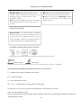
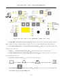
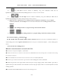
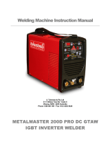
Figure 1: The front panel of the WSME-200D welding power source
1-Output (+)(At the bottom of the front panel):While AC or DC TIG, or pulse TIG welding,or AC/DC
MMA(Manual arc welding or Manual Metal Arc welding),connect to the earth clamp and cable of the work-piece.
2-TIG Torch coupling device (At the bottom of the front panel ):While AC or DC TIG, or pulse TIG
welding,connect to TIG torch.
3-Output (-)(At the bottom of the front panel):While DC MMA,connect to Electrode holder.
4-Torch Control Switch Socket(At the bottom of the front panel):Switch socket of the TIG torch. Connect to
the switch plug of the TIG torch.
5-GAS INPUT(On the back panel):Connect to the Ar gas supply system.
6-2T or Standard,4T or arc-ending,(Crater Current) repeat,
spot-welding and Mode selection button.:This button is called selection button of 2T/4T,Crater
Current Repeat Trigger and spot welding mode.
-12-

INSTALLATION AND USAGE INFORMATION
●4T or arc-ending/ 2Tor Standard for latching and non-latching TIG torch switch control mode.Sometime 4T or 2T is
also called long or short welding TIG torch switch selection mode.
●Mode 2Tor Standard,or :When operating at mode 2T, once the TIG torch switch is triggered, welding
current starts, and when it is released, the welding operation ends .
●Mode 4Tor arc-ending,or :It gives more comfort to the welder for long welding operations.When
operating at mode 4T, once the torch switch is triggered,welding starts,and when it is released the welding operation
will be continue.Once again,the torch switch is triggered,welding operation will be ready to end,and the crater welding
current starts. when it is released the welding operation ends.
●Crater Current Repeat Mode: Under the mode, the crater welding current is repeat until welding operation end.
●Spot welding Mode: Under the mode, the spot welding will be taken on the basis of spot welding parameters until
welding operation end.
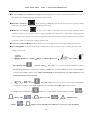
7-Manual arc welding (MMA or Manual Metal Arc ),TIG welding,
Gas-checking and selection button :This button is a selection switch of MMA or TIG,or
Gas-checking.This button is called selection button of MMA,TIG, and Gas-checking.By using this button,MMA
or TIG,or Gas-checking can be selected.When Gas-checking is selected,gas flow rate can be adjusted or Gas
leakage phenomenon can be checked.
8-, and : AC or DC output current,and AC or DC selection button.This button
is called selection button of AC or DC output.By using this button,AC or DC output can be selected.
9-Output (AC) waveform and : Under AC is selected,there are three output waveform, or
Square wave,or Sine-wave and or Triangular wave.
Usually,or Square wave is selected to use under AC is selected by using this button.
-13-

INSTALLATION AND USAGE INFORMATION
10 -Pulse and Compound or complex pulse and button: It is a selection switch of the Pulse and
Compound or complex pulse output current.Under DC,No compound or complex pulse output.
Compound or complex pulse:On the basis of the main pulse,additional pulses are also superimposed.
11-Meter and LED:It is use to display some parameters and unit,for example,current(A),frequency(Hz),
time(S or Sec.)and percent(%).One LED used to show unit of parameter,the meter show parameter.
12-or LED1: Pilot light of Over-heat protection or abnormal condition.
13-LED2: Pilot light of the power supply.
14-Gas Pre or Pre-flow : Pre-flow time of the shielded gas(0~10S,default value 0.1S).
15-Post flow or Post-gas: Post flow time of the shielded gas(0~10S,default value 5S).
16-Hot start:In a short time,striking arc current while starting the welding(5~200A,default value 100A).
17-Arc start current:In a longer time, arc current while starting the welding(5~200A,default value 40A).
18-Slope-up or Rising: Increasing time of the welding output current(0~20S,default value 5S).
19-Max current or Peak current or Pulse peak current : Pulse current or Pulse peak current for Pulse TIG
(5~200A,default value 150A).
20-Welding current: Welding current for No Pulse TIG(5~200A,default value 150A).
21-Base or Background current: Pulse background current for Pulse TIG(5~200A,default value 10A).
22-Spot welding(s) or Spot weld time: spot welding current time for spot welding(0~10S,default value 3S).
23-Pulse width or pulse duty factor: Pulse current time for DC Pulse TIG(10~90%,default value 50%).
24-Pulse frequency: Pulse frequency for DC Pulse TIG(0.1~20Hz,default value 5Hz).
25-AC frequency: AC frequency for AC output current(20~200Hz,default value 80Hz).
26-Clean depth(weld penetration)and Clean width:Balance control of the AC welding output current.Under
AC output current,the longer the negative wave time is,the greater the clean width of weld.The longer the positive wave
time is,the greater the clean depth(weld penetration)(Clean width:10~90%,default value 30%. Clean depth:-50~
50%,default value 0%).
27-Downslop: Decreasing time of the welding output current(0~10S,default value 5S).
28-Current Ending : Final welding current.(5~200A,default value 20A).
-14-

INSTALLATION AND USAGE INFORMATION
29 -Up and Down selection switch or button.By using these button,one LED will be
lighted,correspondingly,one of the mode,welding process,AC or DC,etc. will be selected.
30 -Left and Right selection switch or button.By using these button,one LED will be
lighted,correspondingly,one of the welding parameterswill be selected.
31-Digital encoder or adjustment: It is a welding parameters adjustment controller.By using the Digital
encoder,Up and Down, Left and Right selection switch or button,these above welding parameters can be
Adjusted.
32-.The welding parameters or program saving control switch or button.
33-or .The welding parameters or program calling or load control switch or button.
2.3.2 Connect Output(-) and Output(+)
For DC TIG,DC Pulse TIG and DC MMA, Positive connection means the work-piece is connected to Output (+)
of the welding power source. Negative connection means the work-piece is connected to Output (-) of the welding power
source.
a) DC No Pulse TIG welding process
●Positive connection must be selected for DC TIG.
●Connect the work-piece to Output(+), not Loose.
●Connect the TIG torch to connector of the TIG torch, not Loose.If the water-cooling torch is used,the water-cooling
tubes must be connected.
●Insert the switch cable of the TIG torch into Connector of the torch switch,not Loose .
●Connect Ar gas connector of the torch to gas connector of the welding power source,not Loose.
●Connect the gas tube to the copper nozzle of the back panel. The gas supply system, which includes a gas bottle, a
regulator and a gas outlet, should be well connected in order to keep gas output, which is of critical importance for TIG
welding operation.
●The switch of TIG or MMA must be selected to TIG welding process.
-15-

INSTALLATION AND USAGE INFORMATION
●The switch of AC or DC must be selected to DC.
●Post-flow time of the shielded gas, Increasing time,decreasing time, start ,welding and Final current,etc should be set.
●2T or 4T mode should be set.
●The TIG welding process will be carried out by using TIG torch switch.
●Be sure that connections are correct and not Loose.
b) DC Pulse TIG welding process
●Positive connection must be selected for DC TIG.
●Connect the work-piece to Output(+), not Loose.
●Connect the TIG torch to connector of the TIG torch, not Loose.If the water-cooling torch is used,the water-cooling
tubes must be connected.
●Insert the switch cable of the TIG torch into Connector of the torch switch,not Loose.
●Connect Ar gas connector of the torch to gas connector of the welding power source,not Loose.
●Connect the gas tube to the copper nozzle of the back panel. The gas supply system, which includes a gas bottle, a
regulator and a gas outlet, should be well connected in order to keep gas output, which is of critical importance for TIG
welding operation.
●The switch of TIG or MMA must be selected to TIG welding process.
●The switch of AC or DC must be selected to DC.
●Pulse must be selected.
●Post-flow time of the shielded gas, Increasing time,decreasing time, start and Final current, pulse and background
Current, etc should be set.
●2T or 4T mode should be set .
●The TIG welding process will be carried out by using TIG torch switch.
●Be sure that connections are correct and not Loose.
c) AC No Pulse TIG welding process
●When welding aluminum(AL),aluminum alloy,Magnesium(Mg)and Magnesium alloy,AC TIG must
be selected.
●Connect the work-piece to Output(+), not Loose.
-16-

INSTALLATION AND USAGE INFORMATION
●Connect the TIG torch to connector of the TIG torch, not Loose.If the water-cooling torch is used,the water-cooling
tubes must be connected.
●Insert the switch cable of the TIG torch into Connector of the torch switch,not Loose.
●Connect Ar gas connector of the torch to gas connector of the welding power source,not Loose.
●Connect the gas tube to the copper nozzle of the back panel. The gas supply system, which includes a gas bottle, a
regulator and a gas outlet, should be well connected in order to keep gas output, which is of critical importance for TIG
welding operation.
●The switch of TIG or MMA must be selected to TIG welding process.
●The switch of AC or DC must be selected to AC.
●Square wave must be selected.
●Post-flow time of the shielded gas, Increasing time,decreasing time, start, welding and Final current,etc should be set.
●2T or 4T mode should be set.
●The TIG welding process will be carried out by using TIG torch switch.
●Be sure that connections are correct and not Loose.
d) MMA welding process
●The selection of the positive or negative connection will be depended on the type of the electrode.For the acid welding
electrode,for example E4303 and E6013 , the positive or negative connection are used. For the basic welding electrode,for
example E5015,the negative connection is usually used.
●Connect the work-piece to Output(-), not Loose.
●Connect the Electrode holder to Output(+), not Loose .
●Negative connection is selected for MMA.
●The switch of TIG or MMA must be selected to MMA welding process.
●The switch of AC or DC is selected to DC.
●Hot start ,arc-start, welding current should be set.
●The MMA welding process will be carried out.
-17-

INSTALLATION AND USAGE INFORMATION
CAUTION :
1) For some the electrode,the work-piece must be connected to Output(-), the Electrode holder must be connected
to Output(+).
2) Usually,for most of the electrodes ,the work-piece may be connected to Output(-), the Electrode holder may
be connected to Output(+).
3)Be sure that connections are correct and not Loose.
●Connect the earth clamp firmly to the welding bench or the work-piece
●To increase the quality of the welding, earth clamp on the work piece should be clamped tightly and as close to the
welding area as possible.
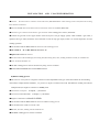
2.3.3 Connect The Gas Cylinder
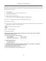
●After placing the gas cylinder , fasten it with the chain. To operate safely and get best results use approved gas regulator.
●Briefly open the gas cylinder valve several times in order to blow out any dirt and particles present .
●Connect the pressure regulator to the shielding gas cylinder .
●Connect one end of gas hose to the gas supply inlet of the welding power source. The other end is for connecting the
hose to pressure regulator.
●Screw the gas hose pressure regulator and open the shielding gas cylinder.
●Setting of the gas flow with the adjustment valve. Usually,the valve is about 4~10L/min.
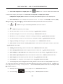
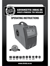
Figure 2: Connection of gas hose and the gas cylinder Figure 3: Open the gas valve and Setting of gas flow
-18-
Gas hose
The gas cylinder
Open the gas cylinder
valve
Setting of gas flow
with the adjustment
valve
Show gas flow
rate
Gas hose

USAGE INFORMATION
3. USAGE INFORMATION
3.1 About Over-heating and Over current
●LED1: Pilot light of over-heating .The LED1 is lighted with thermal overload protection .
LED1 is on, in case that this welding equipment is of overheating protection status. Overheating arises if this welding
power source is overloaded. This welding equipment automatically restarts when the temperature inside of this
welding equipment has fallen, and pilot lamp is off.
CAUTION :In case that this welding equipment is of over current, LED1 is on. At this time ,Switch of the
welding power source must be turn off,and then Switch should be turn on,the welding power source would be able
to weld.
3.2 ADJUSTING THE GAS FLOW for TIG welding process
●The indicators of the regulator shows the flow rate “L/min”.
●Setting of the gas flow with the adjustment valve. Usually,the valve is about 4~10L/min.
3.3 Arc starting for TIG welding process
●The distance between the tungsten and the work-piece should be limited in the range of 1~3mm. Press the torch switch,
the high frequency(HF) is caused. The arc is made between the work and the tip end of the tungsten electrode, and welding
operation is accessible.
3.4 ADJUSTING THE WELDING CURRENT
●The welding current is selected according to the thickness of the work piece and diameter of the welding electrode.
For MMA,the welding current, I2= (25~45)*D.
D-the electrode diameter.2.0mm,2.5mm,3.2mm,4.0mm,5.0mm,etc.
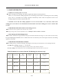
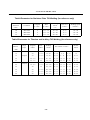
For TIG welding, more detail please refer to the Welding Parameter Selection table 1,2 and 3 etc.
Table1:Parameter for Aluminum Plate AC TIG Welding (for reference only)
Plate
Thickness
(mm)
Connector
Wire
φ(mm)
Tungsten
φ(mm)
Welding
current
(A)
Gas valve
(L/min)
1
Butt Joint
1.6~2.0
1.6~2.0
40~60
4~6
2
Butt Joint
1.6~2.5
1.6~2.0
60~100
5~9
3
Butt Joint
1.6~2.5
2.0~3
100~160
6~10
4
Butt Joint
1.6~2.5
2.0~3
130~200
6~10
-19-
Page is loading ...
Page is loading ...
Page is loading ...
-
 1
1
-
 2
2
-
 3
3
-
 4
4
-
 5
5
-
 6
6
-
 7
7
-
 8
8
-
 9
9
-
 10
10
-
 11
11
-
 12
12
-
 13
13
-
 14
14
-
 15
15
-
 16
16
-
 17
17
-
 18
18
-
 19
19
-
 20
20
-
 21
21
-
 22
22
-
 23
23


Ask a question and I''ll find the answer in the document
Finding information in a document is now easier with AI
Other documents
-
 Tokentools Metalmaster 200d Pro DC GTAW User manual
-
 Arcoweld ArcoTig HF200P User manual
-
 Lotos TIG200DC User manual
-
ESAB 202 AC/DC Inverter Arc Welding Machine User manual
-
-
-
Miller BLUEFAB C350I Owner's manual
-
-
 Strata ADVANCETIG 200 Operating Instructions Manual
-
Crossfire TIGPAC 210 Owner's manual


