Westinghouse MB6(B,E,V)M Installation guide
- Type
- Installation guide

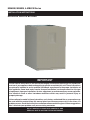
MODULAR INDOOR BLOWER
MB6BM, MB6EM, & MB6VM Series
INSTALLATION INSTRUCTIONS
Please read all information in this manual thoroughly and become familiar with the capabilities
and use of your appliance before attempting to operate or maintain this unit. These instructions
are primarily intended to assist qualifi ed individuals experienced in the proper installation of
this appliance. Some local codes require licensed installation / service personnel for this type
of equipment. Improper installation, service, adjustment, or maintenance may cause explosion,
fi re, electrical shock or other hazardous conditions which may result in personal injury or
property damage.
Unless otherwise noted in these instructions, only factory authorized kits or accessories may
be used with this product. Keep this manual where you have easy access to it in the future. If a
problem occurs, check the instructions and follow recommendations given. If these suggestions
don’t eliminate your problem, call your servicing contractor.
DO NOT DESTROY. PLEASE READ CAREFULLY AND
KEEP IN A SAFE PLACE FOR FUTURE REFERENCE.
IMPORTANT

2
TABLE OF CONTENTS
Important Safety Information ....................................2
Requirements & Codes ..............................................3
General Information ...................................................4
Before You Install this Unit .........................................4
Locating the Indoor Blower ........................................4
Minimum Clearances .................................................4
Operation of Indoor Blower During Construction .......4
Plenums & Air Ducts .................................................5
Supply Air Connections ..........................................5
Return Air Connections ..........................................5
Acoustical Duct Work .............................................5
Air Filters ................................................................6
Unconditioned Spaces ...........................................6
Condensate Drainage ..............................................6
Indoor Blower Installation .........................................6
Upfl ow Installation .....................................................6
Downfl ow Installation .................................................7
Horizontal Installation ................................................8
Horizontal Left Installations ....................................8
Horizontal Right Installations .................................8
Electrical Connections ...............................................9
Pre-Electrical Checklist .............................................9
Line Voltage ...............................................................9
Grounding..................................................................9
Thermostat Connections ...........................................9
Control Board ..........................................................10
Twinning ...............................................................10
Heater Kits...............................................................10
Optional Humidistat .................................................11
Startup & Adjustments ............................................13
Before You Start the Unit .........................................13
Air Circulation Check ...............................................13
Running the Blower Continuously ........................13
System Cooling ....................................................13
System Heating ....................................................13
Turning the Blower Off..........................................13
Blower Confi gurations .............................................13
Determining Nominal System Capacity ...............13
Proper Blower Speed for Multi-speed Units .........13
Variable Speed Units ............................................14
Selecting Continuous Low Speed Operation .......14
Selecting Basic Cooling/Heat Pump Airfl ow ............14
Selecting Minimum Electric Heat Airfl ow .................14
Selecting the Delay Profi le ......................................14
Unit Maintenance ......................................................15
Troubleshooting ........................................................15
Figures & Tables .......................................................16
The information listed below is for reference purposes only
and does not necessarily have jurisdiction over local or state
codes. Always consult with local authorities before installing
any gas appliance.
Duct Systems
• US and CANADA: Air Conditioning Contractors Association
(ACCA) Manual D, Sheet Metal and Air Conditioning
Contractors National Association (SMACNA), or American
Society of Heating, Refrigeration, and Air Conditioning
Engineers (ASHRAE) Fundamentals Handbook
Electrical Connections
• US: National Electrical Code (NEC) ANSI/NFPA 70
• CANADA: Canadian Electrical Code CSA C22.1
General Installation
• US: Current edition of the NFGC and the NFPA 90B. For
copies, contact the National Fire Protection Association
Inc., Batterymarch Park, Quincy, MA 02269; or American
Gas Association, 400 N. Capitol, N.W., Washington DC
20001 or www.NFPA.org
• CANADA: NSCNGPIC. For a copy, contact Standard Sales,
CSA International, 178 Rexdale Boulevard, Etobicoke
(Toronto), Ontario, M9W 1R3 Canada
Safety
• US: (NFGC) NFPA 54–1999/ANSI Z223.1 and the
Installation Standards, Warm Air Heating and Air
Conditioning Systems ANSI/NFPA 90B.
• CANADA: CAN/CGA-B149.1 and .2–M00 National
Standard of Canada. (NSCNGPIC)
Figure 7. MB6 Series Dimensions ........................16
Figure 8. MB6 Series Components ......................17
Blower Performance Data .......................................18
Table 4. MB6BM Airfl ow Data ...............................18
Table 5. MB6EM Airfl ow Data ...............................19
Table 6. MB6VM Airfl ow Data ...............................20
Table 7. MB6VM Min. Elec. Heat Airfl ow ..............20
Table 8. MB6VM Delay Settings ...........................20
Electrical Diagrams .................................................21
Figure 9. MB6(BM&VM) Control Board ................21
Figure 10. MB6EM Control Board ........................21
Figure 11. Variable Speed Control Board .............22
Figure 12. MB6BM Wiring Diagram ......................23
Figure 13. MB6EM Wiring Diagram ......................24
Figure 14. MB6VM Wiring Diagram ......................25
Installation / Performance Checklist .......................28

3
IMPORTANT SAFETY INFORMATION
INSTALLER: Please read all instructions before servicing
this equipment. Pay attention to all safety warnings and
any other special notes highlighted in the manual. Safety
markings are used frequently throughout this manual to
designate a degree or level of seriousness and should not
be ignored. WARNING indicates a potentially hazardous
situation that if not avoided, could result in personal injury
or death. CAUTION indicates a potentially hazardous
situation that if not avoided, may result in minor or moderate
injury or property damage.
WARNING:
ELECTRICAL SHOCK, FIRE OR EXPLOSION
HAZARD
Failure to follow safety warnings exactly could
result in serious injury or property damage.
Improper servicing could result in dangerous
operation, serious injury, death or property
damage.
• Before servicing, disconnect all electrical power
to the indoor blower.
• When servicing controls, label all wires prior
to disconnecting. Reconnect wires correctly.
• Verify proper operation after servicing.
• To minimize equipment failure or personal injury, it is
essential that only qualifi ed individuals install, service, or
maintain this equipment. If you do not posses mechanical
skills or tools, call your local dealer for assistance.
• Follow all precautions in the literature, on tags, and
on labels provided with the equipment. Read and
thoroughly understand the instructions provided with
the equipment prior to performing the installation and
operational checkout of the equipment.
• Use caution when handling this appliance or removing
components. Personal injury can occur from sharp metal
edges present in all sheet metal constructed equipment.
• Do not store any of the following on, or in contact with,
the unit: Rags, brooms, vacuum cleaners, or other
cleaning tools, spray or aerosol cans, soap powders,
bleaches, waxes, cleaning compounds, plastics or
plastic containers, paper bags or other paper products,
gasoline, kerosene, cigarette lighter fl uid, dry cleaning
fl uids, paint thinners, or other volatile fl uids.
REQUIREMENTS & CODES
WARNING:
This unit must be installed in accordance with
instructions outlined in this manual during
the installation, service, and operation of
this unit. Unqualifi ed individuals should not
attempt to interpret these instructions or
install this equipment. Failure to follow safety
recommendations could result in possible
damage to the equipment, serious personal
injury or death.
• The installer must comply with all local codes and
regulations which govern the installation of this type
of equipment. Local codes and regulations take
precedence over any recommendations contained in
these instructions. Consult local building codes for
special installation requirements.
• All electrical wiring must be completed in accordance
with local, state and national codes and regulations
and with the National Electric Code (ANSI/NFPA 70)
or in Canada the Canadian Electric Code Part 1 CSA
C.22.1.
• Install this unit only in a location and position as specifi ed
on pages 4 & 5. This unit is designed only for Indoor
installations and should be located with consideration
of minimizing the length of the supply and return ducts.
See Tables 4 - 8 (pages 18 - 20) and the rating plate for
proper circulating airfl ow data.
• This indoor blower may be used for temporary heating
of buildings or structures under construction. See the
guidelines listed on page 4.
• Installation of equipment may require brazing operations.
Installer must comply with safety codes and wear
appropriate safety equipment (safety glasses, work
gloves, fi re extinguisher, etc.) when performing brazing
operations.
• The installer should become familiar with the units wiring
diagram before making any electrical connections to the
unit. See the unit wiring label or Figures 12 - 14 (pages
23 - 25).
• Always reinstall the doors on the indoor blower after
servicing or cleaning/changing the fi lters. Do not operate
the indoor blower without all doors and covers in place.

4
GENERAL INFORMATION
This appliance has been tested for capacity and effi ciency
in accordance with A.H.R.I. Standards and will provide
many years of safe and dependable comfort, providing
it is properly installed and maintained. Abuse, improper
use, and/or improper maintenance can shorten the life
of the appliance and create unsafe hazards. Please read
all instructions before installing the unit.
Before You Install this Unit
This equipment is securely packaged at the time of
shipment and upon arrival should be carefully inspected
for damage prior to installing the equipment at the job
site. Claims for damage (apparent or concealed) should
be fi led immediately with the carrier.
The cooling load of the area to be conditioned must be
calculated and a system of the proper capacity selected.
It is recommended that the area to be conditioned be
completely insulated and vapor sealed.
Check the electrical supply and verify the power supply
is adequate for unit operation. The system must be wired
and provided with circuit protection in accordance with
local building codes. If there is any question concerning
the power supply, contact the local power company.
Verify the static pressure drop of the coil, fi lter, and duct
work do not exceed the air delivery specs of the indoor
blower.
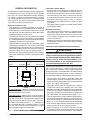
Table 1. Minimum Unit Clearances
INSTALLATION CLEARANCES
Left Side ......... 0 Inches Right Side ...... 0 Inches
Back ............... 0 Inches
Front ...........
†
See Notes
†
NOTES:
Alcove Installations - Allow 24 in. minimum clearance
from front of unit to nearest wall or partition for servicing.
Recommended clearance is 36 in.
Closet installations - require a return air grill installed in
the door or a partially louvered door across the opening
for proper air circulation. For clearances 6” or greater, the
closet must have an open free area of 235 in
2
minimum.
For special clearances between 1” - 5”, requirements
are a louvered door with a minimum of 250 in
2
(1613
cm
2
) free area. A fully louvered closet door is strongly
recommended for both installation types.
REAR
RIGHT
SIDE
LEFT
SIDE
FRONT
Locating the Indoor Blower
• Survey the job site to determine the best location for
mounting the unit. Consideration should be given to
availability of electric power, service access, and noise.
• The dimensions of the room or alcove must be able
to accommodate the overall size of the unit and the
installation clearances listed in Table 1. Physical
dimensions for this indoor blower are shown in Figure
7 (page 16).
• The indoor blower should be installed before routing
the refrigerant tubing.
Minimum Clearances
• This appliance must be installed in accordance with
clearances listed in Table 1. The indoor blower must be
installed with ample clearance for easy access to the
air fi lter, blower assembly, heater assembly, controls,
and vent connections.
• Suffi cient clearance for unobstructed airfl ow through a
louvered door must be maintained in order to achieve
rated performance.
Operation of Indoor Blower During Construction
CAUTION:
Failure to follow these instructions will void the
factory warranty and may signifi cantly reduce
the life or the performance of the indoor blower,
and/or result in other unsafe conditions. It is
the responsibility of the installing contractor
to insure these provisions are met.
Operating an indoor blower in a construction environment
can cause the appliance a variety of problems. Proper
use of commercial portable space heating equipment
during construction is recommended. This indoor blower
may be used during construction if it is not in violation of
any applicable codes and the following criteria are met:
• The installation must meet all applicable codes and
be permanently installed according to the instructions
supplied with the indoor blower. This includes electrical
supply, gas supply, and duct work.
• The indoor blower must be controlled by a properly
installed thermostat that complies with the current
provisions of the NEC (ANSI/NFPA 70) and all applicable
codes having jurisdiction. Thermostat connections must
be made in accordance with instructions supplied with
the indoor blower and thermostat. See pages 9 - 10.
• The installation must include a properly installed fi lter in
the return air system with no by-pass air. The fi lter must
be inspected frequently and replaced when necessary.
• Return air must be supplied unrestricted and located
such that dust and gases from construction activity are
not introduced into the circulating air system.
• Before occupying the structure: The fi lter must be
replaced or cleaned, the duct work must be inspected
and cleaned of any construction debris, and the indoor

5
blower must be cleaned and/or repaired if found to
be dirty, damaged, or malfunctioning in any way by a
qualifi ed HVAC technician. The indoor blower shall be
inspected and approved by applicable local authority
even if this requires redundant inspections.
• The serial number for the indoor blower used during
construction must be submitted in writing (fax and email
also acceptable). This information will be used to track
the long-term affects of indoor blower usage during
construction. Proof of this submittal shall be available
for the fi nal inspection of the indoor blower prior to
occupancy.
with standard practice as specifi ed in the ASHRAE
recommendations for duct transitions.
• The supply air ductwork must be of noncombustible
material for the fi rst 24 inches from the unit. Some
installations with a short, straight run from the unit to
the fi rst branch takeoff may require acoustical lining
inside the supply air ductwork. Consult with local codes
for requirements specifi c to your area.
• Flexible connectors should be used between the unit
and the ductwork to prevent transmission of vibration
from the unit to the structure. If electric heater kits are
installed, heat resistant material must be used for the
fl exible connector at the supply air end of the unit.
• It is good practice to seal all connections and joints
with industrial grade sealing tape or liquid sealant.
Requirements for sealing ducts vary from region to
region. Consult with local codes for requirements specifi c
to your area.
Supply Air Connections
The supply air must be delivered to the heated space by
duct(s) secured to the blower’s casing, running full size
and without interruption. Tape or seal all seams if required
by local code.
Upfl ow & Horizontal Applications: To attach the supply air
duct, bend the fl anges (on top of the unit) outward 90°
with a pair of wide duct pliers. Position the duct on top of
the blower and secure together with sheet metal screws.
Downfl ow Applications: Position the blower over the duct
and secure together with sheet metal screws.
Return Air Connections
The return air must be delivered to the blower by duct(s)
secured to the casing, running full size and without
interruption. Tape or seal all seams if required by local code.
Upfl ow & Horizontal Applications: Position the blower over
the duct and secure together with sheet metal screws.
Downfl ow Applications: To attach the supply air duct,
bend the furnace fl anges outward 90° with a pair of wide
duct pliers. Position the duct on top of the cased coil and
secure together with sheet metal screws.
Acoustical Duct Work
• Certain installations may require the use of acoustical
lining inside the supply duct work. Acoustical insulation
must be in accordance with the current revision of the
Sheet Metal and Air Conditioning Contractors National
Association (SMACNA) application standard for duct
liners. Duct lining must be UL classifi ed batts or blankets
with a fi re hazard classifi cation of FHC-25/50 or less.
• Fiber duct work may be used in place of internal duct
liners if the fi ber duct work is in accordance with the
current revision of the SMACNA construction standard
on fi brous glass ducts. Fibrous duct work and internal
acoustical lining must be NFPA Class 1 air ducts when
tested per UL Standard 181 for Class 1 ducts.
Plenums & Air Ducts
• Plenums and air ducts should be installed in
accordance with the standards of the National Fire
Protection Association Standard for Installation of
Air Conditioning Systems (NFPA 90A), Standard for
Installation of Residence Type Warm Air Heating
and Air Conditioning Systems (NFPA 90B), and all
applicable local codes. NFPA publications are available
by writing to: National Fire Protection Association,
Batterymarch Park, Quincy, ME 02269 or visit
www.NFPA.org online.
WARNING:
All return ducts must be secured to the indoor
blower using appropriate methods. All return
ducts must be adequately sealed. When return
air is provided through the bottom of the unit,
the joint between the indoor blower and the
return air plenum must be air tight.
Return air and circulating air ducts must not be
connected to any other heat producing device
such as a fi replace insert, stove, etc. This may
result in fi re, explosion, carbon monoxide
poisoning, personal injury, or property damage.
• Design the duct work according to methods described
by the Air Conditioning Contractors of America (ACCA).
• This unit is designed only for use with a return and supply
duct. The return air duct must have the same free area
as the opening provided on the blower coil unit. The
ducts should be appropriately sized to the capacity of
the indoor blower to ensure its proper airfl ow rating.
• This unit should be located with consideration of
minimizing the length of the supply and return ducts.
See Tables 4 - 8 (pages 18 - 20) and the rating plate
for proper circulating airfl ow data.
• Whenever the supply or return air ducts pass through
the fl oor, a 1/4” thick noncombustible resilient gasket
must be used between the duct, unit and fl oor
• Use transition fi ttings if the supply and/or return air
openings of the unit do not match the duct openings.
These transitions should be dimensioned in accordance

6
• Damping ducts, fl exible vibration isolators, or pleated
media-style fi lters on the return air inlet of the indoor
blower may be used to reduce the transmission of
equipment noise eminating from the indoor blower. These
treatments can produce a quieter installation, particularly
in the heated space. However, they can increase the
pressure drop in the duct system. Care must be taken
to maintain the proper maximum pressure rise across
the indoor blower, temperature rise and fl ow rate. This
may mean increasing the duct size and/or reducing the
blower speed. These treatments must be constructed
and installed in accordance with NFPA and SMACNA
construction standards. Consult with local codes for
special requirements. For best sound performance, be
sure to install all the needed gaskets and grommets
around penetrations into the indoor blower, such as for
electrical wiring.
Air Filters
WARNING:
Never operate the indoor blower without a fi lter
or with doors removed. Dust and lint can build
up on internal components, resulting in loss of
effi ciency, equipment damage, and possible fi re.
MB6 Series indoor blowers are not equipped with fi lter
racking; however, NORDYNE strongly recommends that
a fi lter be located in the return air duct system. Installing
the fi lter and replacing it every 3 months will increase air
quality throughout the home.
Unconditioned Spaces
All duct work passing through unconditioned space must
be properly insulated to minimize duct losses and prevent
condensation. Use insulation with an outer vapor barrier.
Consult your Distributor for the recommended type and
thickness of insulation for your area as required by local
codes.
Condensate Drainage
CAUTION:
The indoor blower must be level to ensure proper
condensate drainage. An unlevel installation
may result in structural damage, premature
equipment failure, or possible personal injury.
• Modular indoor blowers are intended to be mated with
specifi c NORDYNE C6 cased coils. To ensure proper
condensate drainage, the unit must be installed in a
level position within 1/4 inch over the height, width, and
depth of the unit. The best system performance will be
obtained if the unit is located in a centralized position
with respect to the air distribution system. Refer to the
Installation Instructions supplied with the Cased Coil
for proper condensate drain connections.
• If the indoor blower is located in or above a living space
where damage may result from condensate overfl ow, an
auxiliary drain pan should be installed under the unit.
A separate drain line should extend from the pan to a
conspicuous point and serve as an alarm indicating
that the primary drain is restricted. As an alternative to
a separate drain line, an approved water level indicator
or fl oat switch device should be used to shut down the
unit in the event water is detected in the auxiliary pan.
• During system checkout, inspect the drain line and
connections to verify proper condensate drainage.
• Methods for disposing of condensate vary according
to local codes. Refer to local codes or authority having
jurisidiction for restrictions and proper condensate
disposal requirements.
INDOOR BLOWER INSTALLATION
The MB6 Series indoor blower is shipped ready for vertical
upfl ow installation and is approved for attic, basement,
alcove/closet or crawlspace installation with zero clearance
to combustibles. They may also be applied in downfl ow
or horizontal left and right discharge applications. See
Table 1 (page 4) for required installation clearances. This
appliance is only for indoor use.
NOTE: For shipping purposes, the front and rear joining
brackets are located in the unit’s heater box. Remove
these two items from the heater box before beginning.
• The unit must be leveled at installation and attached to
a properly installed duct system.
• The surface that the indoor blower is mounted on must
provide sound physical support of the unit.
• The indoor blower must be installed so that all electrical
components are protected from water.
• If a louvered door is installed across the front of this
unit, the appliance must be mounted fl ush or behind
front edge of fi nished wall.
• Modular indoor blowers are intended to be mated with
specifi c NORDYNE C6 cased coils. Reference the
Technical Specifi cations for coil mating combinations.
Upfl ow Installation
The MB6 Series indoor blower is shipped from the factory
ready for upfl ow confi guration as shown in Figure 1 (page
7). Return air must must enter from the bottom of the unit.
1. Remove the bracket above the door of the cased coil.
Retain the screws for later use. NOTE: Before mating
the modular unit with the cased coil, clean the mating
surfaces on both units and apply the black neoprene
gasket tape to the top of the coil case (except the rear
surface). Make sure there are no gaps on the front and
side fl anges.
2. Carefully place the modular air handler on top of the
cased coil making sure not to damage the cased coil
fl anges. The units will be fl ush in front with an overhang
in the back as shown in Figure 2 (page 7).

7
Figure 1. Upfl ow & Downfl ow Installation
Upflow
Configuration
Downflow
Configuration
Figure 3. Front Bracket Installation - (Upfl ow Only)
Front Bracket
Figure 2. Rear Bracket Installation - (Upfl ow Only)
Rear Bracket
Modular Air Handler
Cased Coil
Upflow
Configuration
3. Remove the lower front bracket (Figure 9, page 17)
from the modular unit. Retain the screws for later use.
4. Attach the front joining bracket to the front of the modular
unit. Align the screw holes in the bracket with the holes
from the lower front bracket and the top panel of the
coil case. See Figure 3.
5. Secure the bracket with the screws removed earlier in
steps 1 & 2.
6. Attach the rear joining bracket to the backside of the
modular unit and cased coil. Position the bracket so that
it is fl ush with the sides and back of the units with the
1/2” insulation facing the rear gap between the units.
7. Secure the rear bracket with self tapping screws.
Downfl ow Installation
The MB6 Series Modular Air Handler may be installed in
a downfl ow confi guration as shown in Figure 1. Return
air must enter through the top of the unit.
1. Remove the lower front bracket (Figure 9, page 17)
from the modular unit. Retain the screws for later use.
2. Remove the door from the cased coil and the screws
(on the side of the cased coil) securing the lower tie bar
in place. Retain the screws for later use. NOTE: Before
mating the modular unit with the cased coil, clean the
mating surfaces on both units.
3. Flip the modular unit upside down and apply the black
neoprene gasket tape to the top of the indoor blower.
NOTE: The blowers fl anged surface is now beneath the
air handler and will connect with the supply air duct.
Figure 4. Downfl ow Brackets
Rear
Bracket
Front
Bracket
Cased
Coil
Modular
Air Handler

8
IMPORTANT: If the webbing is not removed, the
condensate will not drain properly and ceiling damage
may occur.
3. Insert the plug (from horizontal drain pan) into the open
and unused drain hole in the drain pan at the bottom
of the unit to block bypass air.
4. Remove the corresponding drain line knockout from
the coil access door to allow access to the horizontal
drain.
5. Replace the door and attach the drain line.
Horizontal Right Installations
1. Remove the coil access door. Unscrew the line-set tube
close-off plate from the front left cabinet rail.
2. Slide the coil and drain pan assembly out of the unit.
3. Remove the sheet metal hairpin covers (if supplied)
from the back of the coil and discard.
4. Place the horizontal drain pan on the opposite side of
the coil. On units with 2 sets of knockouts, remove the
other set of knockouts in the coil spacing plates and
insert support rod.
5. Slide the coil and the horizontal drain pan assembly
back into the unit. Re-attach the tube close off plate.
6. Remove the plug from one of the threaded holes
in the horizontal drain pan. Completely remove the
webbing located in the threaded holes of the drain
pan. IMPORTANT: If the webbing is not removed, the
condensate will not drain properly and ceiling damage
may occur.
7. Insert the plug (from horizontal drain pan) into the open
and unused drain hole in the drain pan at the bottom
of the unit to block bypass air.
8. Remove the corresponding drain line knockout from
the coil access door to allow access to the horizontal
drain.
9. Replace the door and attach the drain line.
4. Carefully place the cased coil on top of the modular
air handler. NOTE: Make sure the units are fl ush in the
front and on the sides with a “step” fi t in the back and
that there are no gaps on the sides. See Figure 4.
5. Attach the front joining bracket to the cased coil and
the air handler. Align the screw holes in the bracket with
the holes where the lower front bracket and lower tie
bar were attached.
6. Secure the bracket to the modular unit and the cased
coil with the screws removed earlier in steps 1 & 2.
7. Attach the rear joining bracket to the backside of the
modular unit. Position the bracket so that it is fl ush with
the sides and back of the units with the 1/2” insulation
facing the rear gap between the units.
8. Secure the rear bracket to the modular unit and cased
coil with self-tapping screws.
Horizontal Installation
MB6 indoor blowers are shipped from the factory ready
for horizontal left applications and horizontal right
applications. The blowers can be installed horizontally
in an attic, basement, crawl space or alcove. They can
also be suspended from a ceiling in a basement or utility
room in either a right to left airfl ow or left to right airfl ow.
A typical installation of the unit in a suspended horizontal
application is shown in Figure 5.
When mating the blower and coil for horizontal left or right
applications, reference the upfl ow mating directions on
pages 6 & 7. Make sure to account for the coil orientation
by confi guring the coil drain pan assembly properly. Multi-
position procedures are also available in the cased coil
Installation Instructions supplied with the unit.
NOTES:
• In many applications when joined with a C6 cased
coil, the shorter horizontal drain pan extension which
is included with the MB6 must be used. This is to avoid
any interference with the extension included with the
C6 and the blower.
• indoor blowers may or may not be shipped from the
factory with all the parts required for horizontal left
applications and horizontal right applications. If your
unit does not have parts for a horizontal application, a
kit is available.
If suspending the indoor blower from the ceiling, assemble
a support frame (Figure 4) using slotted iron channel and
full threaded rod. Fasten the frame together with nuts,
washers, and lockwashers. Secure the support frame to
the rafters with lag bolts. The indoor blower can also be
suspended using steel straps around each end of the unit.
The straps should be attached to the indoor blower with
sheet metal screws and to the rafters with bolts.
Horizontal Left Installations
1. Remove the coil access door.
2. Remove the plug from one of the threaded holes in the
horizontal drain pan. Completely remove the webbing
in the threaded holes of the horizontal drain pan.
Figure 5. Unit Horizontally Suspended
Threaded
Rod
Lag
Bolt
Nuts (x2)
Washer
and
Lockwasher
Nuts (x2)

9
ELECTRICAL CONNECTIONS
WARNING:
ELECTRICAL SHOCK, FIRE OR EXPLOSION
HAZARD
Failure to follow safety warnings exactly could
result in serious injury or property damage.
Improper servicing could result in dangerous
operation, serious injury, death or property
damage.
• Before servicing, disconnect all electrical power
to the indoor blower.
• When servicing controls, label all wires prior
to disconnecting. Reconnect wires correctly.
• Verify proper operation after servicing.
• Electrical connections must be in compliance with
all applicable local codes and ordinances, and with
the current revision of the National Electric Code
(ANSI/NFPA 70).
• For Canadian installations, the electrical connections
and grounding shall comply with the current Canadian
Electrical Code (CSA C22.1 and/or local codes).
Pre-Electrical Checklist:
Verify the voltage, frequency, and phase of the supply
source match the specifi cations on the unit rating plate.
Verify that the service provided by the utility is suffi cient
to handle the additional load imposed by this equipment.
See the unit wiring label or Table 2 (page 10) for proper
high and low voltage wiring.
Verify factory wiring is in accordance with the unit wiring
diagram (Figures 12 - 14, pages 23 - 25). Verify none of
the connections loosened during shipping or installation.
Line Voltage
• An electrical disconnect must be located within sight
of and readily accessible to the unit. This switch shall
be capable of electrically de-energizing the outdoor unit.
See unit data label for proper incoming fi eld wiring. Any
other wiring methods must be acceptable to authority
having jurisdiction.
• It is recommended that the line voltage to the unit be
supplied from a dedicated branch circuit containing the
correct fuse or circuit breaker for the unit.
• Overcurrent protection must be provided at the branch
circuit distribution panel and sized as shown on the unit
rating label and according to applicable local codes. See
the unit rating plate and Table 2 (page 10) for maximum
circuit ampacity and maximum overcurrent protection
limits.
• The installer should become familiar with the wiring
diagram/schematic before making any electrical
connections to the unit. See the unit wiring label or
Figures 12 - 14.
• Use only copper wire for the line voltage power supply
to this unit. Use proper code agency listed conduit and
a conduit connector for connecting the supply wires to
the unit. Aluminum supply wire may be used if a heater
kit is installed.
• If replacing any of the original wires supplied with the
unit, the replacement wire must be copper wire consisting
of the same gauge and temperature rating.
• Provide power supply for the unit in accordance with the
unit wiring diagram, and the unit rating plate. Use UL
listed conduit and conduit connectors for connecting the
supply wires to the unit and for proper grounding. Field
supplied bushings for the power supply cables must be
added to support and protect the power supply cables.
• All 208/230 Volt units are shipped from the factory wired
for 240 volt operation. For 208V operation, remove the
lead from the transformer terminal marked 240V and
connect it to the terminal marked 208V.
Grounding
WARNING:
The unit cabinet must have an uninterrupted
or unbroken electrical ground to minimize
personal injury if an electrical fault should occur.
Do not use gas piping as an electrical ground!
This unit must be electrically grounded in accordance
with local codes or, in the absence of local codes, with
the National Electrical Code (ANSI/NFPA 70) or the CSA
C22.1 Electrical Code. Use the grounding lug provided in
the control box for grounding the unit.
Thermostat Connections
• Thermostat connections shall be in accordance with the
instructions supplied with the thermostat and the indoor
equipment. The low voltage wires must be properly
connected to the units low voltage terminal block.
• A single stage thermostat is used with this equipment
and must operate in conjunction with any installed
accessories. Typical AC and heat pump connections
are shown in Figure 6 (page 12).
CAUTION:
Isolation must be maintained from the external
Class 2 output of any transformer in a cooling
circuit. Use a thermostat with isolating contacts
to prevent inter-connection of Class 2 outputs.
• Where local codes require that the thermostat wiring
must be routed through a conduit or raceway, splices
can be made inside the unit; however, all wiring must
be NEC Class 1 and must be separated from incoming
power leads.
• The thermostat should be mounted about 5 feet above
the fl oor on an inside wall. DO NOT install the thermostat

10
on an outside wall or any other location where its
operation may be adversely affected by radiant heat from
fi replaces, sunlight, or lighting fi xtures, and convective
heat from warm air registers or electrical appliances.
Refer to the thermostat manufacturer’s instruction sheet
for detailed mounting and installation information.
• Install the grommet (packed with the unit) in the hole
for low-voltage wires. Connect the low-voltage wiring to
the thermostat and the outdoor unit and the appropriate
screw terminal located on the control board. NOTE:
When the low voltage wires are positioned in this
grommet, the grommet will prevent chafi ng and/or
shorting of the low voltage leads.
Important! On variable speed models when the unit is
used in an air conditioning system, connect the O terminal
to the Y terminal. See Figure 6 (page 12).
Control Board
The control board in the indoor blower controls the timing
sequence of the elements. Depending on the thermostat
connection, there are multiple timing sequence variations
that can be chosen. See Table 3 (page 11) for element
sequence timing. The board also is equipped with a 3
second blower on delay and a 15 second blower off delay.
See Figures 9 - 11 (pages 21 & 22).
Twinning
MB6 indoor blowers are not supplied with a built in twinning
capability. To connect two indoor blowers to a common
single stage AC condensing unit or heat pump, a twinning
kit is available for fi eld installation. Please follow the
instructions supplied with the kit.
NOTE: Variable speed indoor blowers cannot be twinned.
Heater Kits
Field-installed electric heater kits are available. Instructions
for installing the electric heaters are included with the
heaters. See heater kit information can be found in the
Technical Specifi cations.
Indoor blowers set up with 15 kw or more of electric heat
will normally be confi gured for multiple-circuit power supply.
They may, however, be connected to a single-circuit power
supply with the addition of a single circuit accessory kit
(See Technical Specifi cations). Select the wire size and
over-current protection in accordance with the minimum
circuit ampacity and maximum over-current protection
shown in Table 2.
Table 2. Minimum Circuit Ampacity & Maximum Overcurrent Protection
Aux. Heat Installed
(Nom. KW)
Single Phase, 240 VAC, 50 & 60Hz Single Phase, 208 VAC, 60Hz
NONE 005H 008H 010H 015H 020H NONE 005H 008H 010H 015H 020H
Single Circuit
***Min. Circuit Amp. 7.5 32.5 46.6 57.5 82.5 107.5 7.5 29.1 41.2 50.8 72.4 94.0
*Wire AWG 75
o
C 14 8 8(6**) 6 4(3**) 2 14 10(8**) 8 6 4 3
Maximum Over-current
Rating
15 40 50 60 90 125 15 30 50 60 80 100
Multiple Circuit
Circuit A
***Min. Circuit Amp. 7.5 32.5 46.6 57.5 57.5 57.5 7.5 29.1 41.2 50.8 50.8 50.8
*Wire AWG 60
o
C 14 8 6 4 4 4 14 10(8**) 6 6 6 6
*Wire AWG 75
o
C 14 8 8(6**) 6 6 6 14 10(8**) 8 6 6 6
Maximum Over-current
Rating
15 40 50 60 60 60 15 30 50 60 60 60
Circuit B
***Min. Circuit Amp. - - - - 25.0 50.0 - - - - 21.6 43.3
*Wire AWG 60
o
C ----106----106
*Wire AWG 75
o
C ----108----108
Maximum Over-current
Rating
- - - - 30 60 - - - - 25 50
Circuit C
***Min. Circuit Amp. - - - - - - - - - - - -
*Wire AWG 60
o
C ------------
*Wire AWG 75
o
C ------------
Maximum Over-current
Rating
------------
*All wire sizes for copper conductors only, based on NEC Table 310-16.
**Required for C-cabinet variable speed.
***Circuit ampacity slightly higher for variable speed. See label on blower.

11
Control
Signal
Operation Board Action
W1 only
On
Stage 1 Heat on instantly
Heat blower on after 3 second delay
Stage 3 & 5 Heat on after 1 minute delay
Stage 2 Heat on after 2 minute delay
Stage 4 & 6 Heat on after 3 minute delay
Off
Heat stages off instantly
Blower off after 15 second delay
W1 & W2
On
Stage 1 Heat on instantly
Heat blower on after 3 second delay
Stage 3 & 5 Heat on after 10 second delay
Stage 2 Heat on after 20 second delay
Stage 4 & 6 Heat on after 30 second delay
Off
Heat stages off instantly
Blower off after 15 second delay
W1 & Y/Y2
On
Stage 1 Heat on instantly
Cool blower on after 3 second delay
Stage 3 & 5 Heat on after 1 minute delay
Stage 2 Heat on after 2 minute delay
Stage 4 & 6 Heat on after 3 minute delay
Off
Heat stages & Cool blower off instantly
Heat blower energizes and then turns off after 15
second delay
W1, W2 &
Y/Y2
On
Stage 1 Heat on instantly
Cool blower on after 3 second delay
Stage 3 & 5 Heat on after 10 second delay
Stage 2 Heat on after 20 second delay
Stage 4 & 6 Heat on after 30 second delay
Off
Heat stages and Cool blower off instantly
Heat blower energizes and then turns off after 15
second delay
Table 3. Heating Element Logic
When electric heat packages with circuit breakers are
fi eld-installed, the circuit breaker may be used as a
disconnecting means in most applications. Reference the
NEC and local codes for disconnect requirements.
If a heater kit is installed:
The MB6 indoor blower is shipped from the factory without
an electric heater kit installed. If Electric heat is desired,
the H6HK heater kit may be purchased separately and
fi eld installed. Determine the correct size heater kit for your
unit by referring to the list below or the units rating label.
A Size Cabinet ............................................... 15Kw max
B Size Cabinet ............................................... 20Kw max
C Size Cabinet ............................................... 20Kw max
1. Connect the 2 wire plug of the indoor blower to the
mating 2 wire plug of the heater kit.
2. Connect the line voltage leads to the circuit breaker or
terminal block provided.
3. Connect the heater kit plug with the mating receptacle
on the indoor blower control board.
If a heater kit is not installed:
1. Remove the 2 wire plug of the indoor blower by cutting
the wires and discarding the plug.
2. Strip the ends of the 2 indoor blower wires and connect
to the line-voltage leads with the 2 wire nuts provided.
Optional Humidistat
(MB6VM Models Only)
The optional humidistat may be installed in the return air
duct to provide excellent humidity control when needed
and maximum system capacity and energy effi ciency
when humidity levels are normal. The humidistat senses
when humidity in the return air stream is above a preset
level (fi eld adjustable) and sends a signal to the motor to
reduce the airfl ow so that more moisture may be removed
until the humidity level drops. The indoor blower is pre-
programmed for humidistat operation.
Remove jumper connector installed between the two
terminals marked HUM on the variable speed board.
Install the humidistat in the return air duct as directed
in the installation instructions included with the kit. Wire
the humidistat through the low-voltage wire entrance in
the indoor blower to the control board terminal marked
DEHUM. Wire the humidistat to open on rise in humidity.

12
Figure 6. Typical Air Conditioner & Heat Pump System Connections
G
R
W
2
C
EO
Y
Thermostat
G
R
W
Thermostat
Y
C
Y
GRW
Thermostat
Y
C
Air
Handler
Air
Conditioner
Y
Typical Air Conditioner with
Standard Air Handler
GRC E
O
Y
Thermostat
Typical Heat Pump w/Standard Air Handler
Typical Air Conditioner with
Variable Speed Air Handler
Typical Heat Pump with Optional Outdoor
Thermostat and Variable Speed Air Handler
NOTE: Jumper W1
&W2 together for
shorter staging time.
W2
W1
O
Y/Y2
G
R
C
W2
W1
O
Y/Y2
G
R
C
W2
W1
O
Y/Y2
G
R
C
W2
W1
O
Y/Y2
G
R
C
G
R
W2
C
EO
Y1
Thermostat
OD
Stat
O
Y1
R
C
GR
W
Thermostat
Y1
C
Y1
W2
E
Typical 2-Stage Air Conditioner
with Variable Speed Air Handler
Typical 2-Stage Cooling Heat Pump with
Optional Outdoor Thermostat &Variable
Speed Air Handler
W2
W1
O
Y/Y2
G
R
C
W2
W1
O
Y/Y2
G
R
C
Y2
Y2
Y2
Y2
W1
W3
R
Y1
Y1
Y1
Y1
Y1
Y1
Air
Conditioner
Air
Handler
NOTE: Jumper W1
&W2 together for
shorter staging time.
NOTE: Jumper W1
&W2 together for
shorter staging time.
NOTE: For AC applications, the O & Y
connection must be connected as shown.
Air
Conditioner
Air
Handler
NOTE: For AC applications, the O & Y
connection must be connected as shown.
Heat Pump
Air
Handler
NOTE: Jumper W1
&W2 together for
shorter staging time.
NOTE: Jumper W1
&W2 together for
shorter staging time.
NOTE: Jumper W1
&W2 together for
shorter staging time.
Heat Pump
OD
Stat
E
O
W2
R
C
Y
Air
Handler
Air
Handler
W
2
O
W2
R
C
Y
Heat Pump
NOTE: Jumper between
W2 & E is required when
no OD T-Stat is used.
* On single stage systems connect to Y/Y2 to obtain selected cooling speed

13
Blower Confi gurations
Determining Nominal System Capacity
To select the appropriate airfl ows for the indoor blower,
the nominal system capacity must be known. The nominal
system capacity is always the nominal capacity of the
outdoor unit. However, in some situations the nominal
system capacity may not be the same as the capacity
rating of the indoor blower. Always refer to the outdoor units
capacity rating to determine the nominal system capacity.
Proper Blower Speed for Multi-Speed Units
(MB6BM & MB6EM Models)
CAUTION:
To avoid personal injury or property damage,
make sure the motor leads do not come into
contact with any uninsulated metal components
of the unit.
The blower speed is preset at the factory for operation
at the same speed for heating and cooling, by using the
jumping terminal on the blower motor and connecting it
to the desired speed with both the red and black wires
connected to the jumping terminal. NOTE: The control
board is programmed with a 40 second off delay in the
cooling mode for optimum system performance and
effi ciency.
For optimum system performance and comfort, it may be
necessary to change the factory set speed. See Tables 4-8
(pages 18-20) for airfl ow data. To change the blower speed:
1. Disconnect all electrical power to the unit and remove
the upper door.
2. Remove the black and red wires from the blower motor
jumping terminal. Discard the blower motor jumping
terminal.
3. Connect the heating speed wire (red) and the cooling
speed wire (black) to the desired blower speed marked
on the terminal block of the blower motor. For standard
3-speed motors:
• Terminal 4 = High speed
• Terminal 5 = Medium speed
• Terminal 6 = Low speed
MB6EM units equipped with selectable blower speeds:
• Terminal 1 = Low speed
• Terminal 2 = Medium Low speed
• Terminal 3 = Medium speed
• Terminal 4 = Medium High speed
• Terminal 5 = High speed
4. Replace the upper door and secure it to the unit.
5. Restore power to the unit.
STARTUP & ADJUSTMENTS
Before You Start the Unit
Prior to start-up, complete the following inspections:
Verify the unit is level and properly located with adequate
clearances for servicing the unit. See Table 1 (page 4).
Check condensate drain line(s) for proper drainage.
Verify the surrounding area and top of the unit is free
from obstructions and debris.
Check all duct connections. Make sure the duct work
is adequately sealed to prevent air leakage.
Check all coil connections for leaks.
Verify that the line voltage power leads are securely
connected and the unit is properly grounded. Make sure
all doors are installed before restoring power to the unit
Verify the thermostat is wired correctly. Make sure all
low voltage wires are securely connected to the correct
leads of the low voltage terminal strip.
Verify the power supply branch circuit overcurrent
protection is sized properly.
Verify fi lter is properly and securely installed.
Air Circulation Check
Running the Blower Continuously
Set the thermostat’s system mode to OFF and the
thermostat’s fan mode to ON. The blower motor should
run continuously. Check for air delivery at the register(s).
Make sure that there are no obstructions at the registers
or in the ducts.
NOTE: If blower is turning opposite of arrow direction, shut
off main power to the unit and switch any two fi eld wires
at the disconnect. DO NOT alter unit wiring.
System Cooling
1. Set the thermostat’s system mode to COOL and fan
mode to AUTO. Lower the thermostat’s temperature
mode below room temperature and observe that the
blower energizes. Check the air being discharged at
the register is cooler than room temperature. Verify
unit refrigerant pressures are in order. Blower should
be turning in direction indicated by arrow.
NOTE: DO NOT alter unit wiring. Listen for any unusual
noises. Locate the source and correct as needed.
2. Allow the unit to run for several minutes and then set
the thermostat’s temperature above room temperature.
Verify the blower cycles off with the thermostat.
System Heating
1. Set the thermostat’s system mode to HEAT and the fan
mode to AUTO. Increase the thermostat’s temperature
above room temperature and observe that the blower
energizes. Check the air being discharged at the register
is warmer than room temperature.
2. Allow the unit to run for several minutes and then set
the thermostat’s temperature below room temperature.
Verify the blower cycles off with the thermostat.
Turning the Blower Off
Set thermostat’s fan mode to AUTO, the blower will shut
down immediately.

14
Variable Speed Units (MB6VM Models)
Variable Speed units have been designed to give
the installer maximum fl exibility to optimize system
performance, effi ciency, and comfort. Because there are
so many different ways to set up the indoor blower it is
important to read and follow these directions carefully.
Variable speed air handlers are equipped with a
microprocessor-controlled variable speed motor that is
pre-programmed to deliver optimum airfl ow in a variety
of conditions and system confi gurations. See Figure 11.
Before operation, the indoor blower must be confi gured to
match the unit with the system, system options, and climatic
conditions. When confi gured, the indoor blower responds
directly to the thermostat inputs, as well as the optional
humidistat (see page 11). During normal operation, the
motor will gradually change speeds during start-up, shut
down, when thermostat inputs change, and when the duct
static pressure changes (vents closed or opened, fi lter
clogging, etc.). The indoor blower is confi gured by setting
the selector switches and removing jumper connectors.
Selecting continuous low speed fan operation
The indoor blower is equipped with an option of continuous
low speed fan operation. When G is energized without Y/
Y2, the indoor blower will operate using a percentage of
the cooling speed. With G & Y/Y2 or Y/Y2 energized, the
indoor blower will operate in the selected cooling speed
(including 40 sec blower-off delay).
Selecting Basic Cooling/Heat Pump Airfl ow
The basic cooling/heat-pump airfl ow is selected by setting
switches 1 through 4 on the thermostat input board (located
on the blower). All airfl ows for other modes of operation
(except electric heat) are determined by this basic setting.
FAN ONLY would deliver 50% of the selected cooling
airfl ow.
Table 6 (page 20) lists the basic airfl ow values
versus the airfl ow selector switch settings and ranges of
basic air fl ow settings recommended for each nominal
system capacity.
• When operating in the heat pump mode, a higher
basic airfl ow setting will increase the energy effi ciency
and capacity but will also decrease the supply air
temperature.
• For maximum capacity and energy effi ciency, select an
airfl ow at or near the top of the range for that nominal
capacity.
• For maximum dehumidifi cation, select an airfl ow near the
middle or bottom of the range for that nominal capacity.
Additional information on humidity control can be found
in the Humidistat and Delay Setting sections.
• For thermostats with a dehumidifi er output, use a fi eld
supplied wire to connect the thermostat’s dehumidifi er
output to the terminal marked DHUM. The thermostat
should be set so that the DHUM output should be high
(positive) when dehumidifi cation is needed. See also
Optional Humidistat section on page 11.
IMPORTANT! If coil icing is observed, the basic cooling/
heat-pump airfl ow selected may be too low. Verify the
setting selected is within the range shown in Table # and
that the the system is properly charged. Please refer to the
instructions supplied with the outdoor unit. If icing continues
to occur, raise the selected airfl ow one or two steps.
NOTES:
• The CFM values listed in Table 6 are not dependent
on duct static pressure. The variable speed motor
automatically compensates for changes in duct static
pressure (within the limits of the motor).
• Variable speed indoor blowers with SEER ratings higher
than 15 are matched with a 2-stage cooling outdoor
unit. They are programmed to operate at 75% of the
selected airfl ow while the system is in the lo-cool mode
and 100% of the selected airfl ow while in hi-cool mode.
Selecting Minimum Electric Heat Airfl ow
The minimum electric heat airfl ow setting controls the
minimum air fl ow that will be produced whenever electric
heater kits are used. When the electric heater kit is
energized along with a heat pump, the airfl ow may be
higher depending on the basic cooling/heat-pump airfl ow
setting. The minimum electric heat airfl ow is selected by
setting switches 5 & 6. Recommended switch settings are
listed in Table 7 (page 20). NOTE: The minimum electric
heat airfl ow setting may be set higher, but must never be
set lower than the setting shown in Table 6.
Selecting the Delay Profi le
Delay profi le selection controls the start-up and shut-down
characteristics of the air handler. By varying the start-up
and shut-down characteristics of the air handler the system
can be optimized for energy effi ciency, humidity control, and
comfort. The delay profi le is selected by setting switches
7 and 8. See Table 8 (page 20).
Select Delay A or “Delay B” for highest energy effi ciency.
Delay A has a two-step “on” delay. The blower will begin
operation at 31% airfl ow for 30 seconds. The second step
operation is 75% airfl ow for 30 seconds. After the two-step
“on” delay has been completed, the blower operation will
be 100% until the thermostat has been satisfi ed. Delay
A also provides a 60 second “off” delay at 50% airfl ow.
Delay B has a single step 30 second “on” delay at 50%
airfl ow. Delay B also provides a 90 second “off” delay at
50% airfl ow. Select the delay profi le which is most suited
to the application.
The DHUM delay profi le may be used when humidity control
is desired without the use of the optional humidistat. If the
DHUM delay profi le is selected, the air handler will run at
75% airfl ow for the fi rst 10 minutes of each cooling cycle.
If the DHUM delay profi le is selected, the basic cooling/
heat-pump speed should be selected at or near the top
of the range for that nominal capacity (see Table 6).

15
UNIT MAINTENANCE
Proper maintenance is most important to achieve the
best performance from an indoor blower. Some of the
components and their locations are shown in Figure 8
(page 17). If any component of the indoor blower must be
replaced, use only factory authorized replacement parts
specifi ed in the Replacement Parts List provided online.
WARNING:
ELECTRICAL SHOCK, FIRE OR EXPLOSION
HAZARD
Failure to follow safety warnings exactly could
result in serious injury or property damage.
Improper servicing could result in dangerous
operation, serious injury, death or property
damage.
• Before servicing, disconnect all electrical power
to the indoor blower.
• When servicing controls, label all wires prior
to disconnecting. Reconnect wires correctly.
• Verify proper operation after servicing.
• These maintenance instructions are primarily intended
to assist qualifi ed technicians experienced in the proper
maintenance and operation of this appliance.
• Always reinstall the doors on the indoor blower after
servicing or cleaning/changing the fi lters. Do not operate
the indoor blower without all doors and covers in place.
• To achieve the best performance and minimize equipment
failure, it is recommended that a yearly maintenance
checkup be performed. At a minimum, this check should
include the following items:
Air Filter(s)
WARNING:
Never operate the indoor blower without a fi lter
in place. Dust and lint in the return air can build
up on internal components, resulting in loss of
effi ciency, equipment damage, and possible fi re.
Inspect and replace the air fi lter at the beginning of heating
and cooling season. It is recommended that the fi lter
be cleaned or replaced monthly. Newly built or recently
renovated homes may require more frequent changing
until the construction dust has minimized. Filters designed
to remove smaller particles such as pollen, may require
additional maintenance.
Blower Compartment
Dirt and lint can create excessive loads on the motor
resulting in higher than normal operating temperatures
and shortened service life. It is recommended that the
blower compartment be cleaned of dirt or lint that may
have accumulated in the compartment or on the blower
and motor as part of the annual inspection.
Blower Fan Wheel
Inspect the blower wheel blades for accumulations of dirt
and clean if necessary. Inspect mounting nut for tightness.
Blower Motor & Assembly
Inspect the blower assembly and motor mounting
brackets for tightness and corrosion. Correct defi ciencies
if necessary. The blower motor contains sealed bearings
and under normal operating conditions, no maintenance
is necessary for the life of the equipment.
Cooling Coil
Inspect the cooling coil, drain pan, and condensate drain
at the beginning of each cooling season for cleanliness.
Clean these components as necessary using a mild
detergent and water. After cleaning, fl ush the coil, drain
pan, and condensate drain to remove all detergent.
IMPORTANT: Use caution when cleaning these
components so that the insulation does not get wet.
TROUBLESHOOTING
If the indoor blower fails to operate, check the following:
• Is the electric turned on?
• Is the thermostat operating properly?
• Are the blower compartment door(s) in place?
• Is the indoor blower disconnect closed?
• Has the circuit breaker tripped or the control board fuse
burned open?
• Are any manual reset switches open?
• Is the fi lter dirty or plugged?

16
FIGURES & TABLES
Figure 7. MB6 Series Physical Dimensions
Cabinet Size Dimension A Dimension B Dimension C
A 12-3/4 24-3/4 14-1/4
B 12-3/4 24-3/4 17-1/2
C 18-1/4 27-1/2 21
"B"
"A"
12 7/8
3/4 TYP.
1 3/4
Ø 1 7/8 K.O.
3 1/4
1 1/4
"C"
22”
1”
1 7/8
3 1/2
5 1/2
2 5/8
Ø1 1/8” K.O.
(TYP.)
1 1/4
2 7/8
TOP
VIEW
Ø 7/8 K.O.
1 7/8
Ø1 1/8” K.O.
Ø1 3/4” K.O.
3/4 TYP.
FRONT
VIEWLEFT SIDE
RIGHT SIDE
BOTTOM
VIEW

17
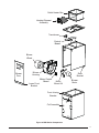
Heating Element
Assembly
Motor
Mount Kit
Blower
Motor
Blower
Wheel
Blower
Housing
Transformer
Control
Board
Coil Assembly
Outlet Heater Box
Lower Front
Bracket
Blower
Door
Motor Control
Board
Rear
Bracket
Front Joining
Bracket
Figure 8. MB6 Series Components

18
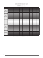
Table 4. Airfl ow Data for MB6BM Indoor Blowers
MB6BM Airfl ow Data
Dry Coil ESP 0.10 0.20 0.30 0.40 0.50 0.60 0.70 0.80
0800
A-Cabinet
Low 685 645 605 565 515 465 405 345
Corrected ESP
1
0.07 0.19 0.30 0.42 0.53 0.65 0.76
Med 860 825 780 735 680 625 565 500
Corrected ESP
1
0.11 0.23 0.36 0.48 0.60 0.72
High 1070 1025 975 920 860 800 730 660
Corrected ESP
1
0.14 0.27 0.40 0.53 0.67
1200
A-Cabinet
Low 850 825 795 755 705 645 580 510
Corrected ESP
1
0.04 0.15 0.27 0.38 0.50 0.62 0.74
Med 1120 1085 1045 995 940 875 800 715
Corrected ESP
1
0.04 0.17 0.29 0.42 0.55 0.68
High 1275 1235 1185 1130 1070 1005 935 860
Corrected ESP
1
0.10 0.23 0.36 0.49 0.63
1200
B-Cabinet
Low 995 955 910 845 780 705 610 530
Corrected ESP
1
0.08 0.19 0.31 0.42 0.54 0.65 0.76
Med 1335 1290 1235 1175 1100 1015 925 805
Corrected ESP
1
0.10 0.22 0.34 0.46 0.59 0.71
High 1470 1425 1360 1300 1225 1135 1050 920
Corrected ESP
1
0.08 0.22 0.37 0.51 0.65
1600
C-Cabinet
Low 1035 1005 970 925 875 825 770 710
Corrected ESP
1
0.11 0.22 0.33 0.44 0.54 0.65 0.76
Med 1635 1595 1525 1475 1405 1305 1210 1060
Corrected ESP
1
0.08 0.20 0.32 0.44 0.57 0.69
High 1910 1840 1760 1685 1595 1495 1395 1250
Corrected ESP
1
0.14 0.26 0.39 0.52 0.65
2000
C-Cabinet
Low 1520 1510 1500 1485 1465 1440 1415 1385
Corrected ESP
1
0.11 0.21 0.31 0.42 0.52 0.62 0.72
Med 1900 1885 1860 1830 1790 1740 1680 1620
Corrected ESP
1
0.06 0.16 0.27 0.37 0.48 0.59 0.70
High 2245 2195 2135 2080 2015 1950 1885 1800
Corrected ESP
1
0.12 0.23 0.34 0.45 0.56 0.67
1
ESP estimate with wet coil and fi lter
BLOWER PERFORMANCE DATA

19
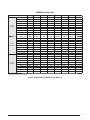
Table 5. Airfl ow Data for MB6EM Indoor Blowers
MB6EM Airfl ow Data
Dry Coil ESP 0.10 0.20 0.30 0.40 0.50 0.60 0.70 0.80
1200
A-Cabinet
Tap 1 840 800 760 715 670 625 580 530
Corrected ESP
1
0.08 0.19 0.30 0.42 0.53 0.64 0.75
Tap 2 881 846 810 772 733 693 652 609
Corrected ESP
1
0.07 0.18 0.29 0.40 0.51 0.62 0.73
Tap 3 976 942 907 872 836 799 761 722
Corrected ESP
1
0.03 0.15 0.26 0.37 0.48 0.59 0.70
Tap 4 1250 1224 1194 1159 1119 1074 1025 971
Corrected ESP
1
0.08 0.20 0.33 0.45 0.58
Tap 5 1380 1338 1293 1243 1189 1131 1068 1001
Corrected ESP
1
0.03 0.16 0.30 0.43 0.56
1600
B-Cabinet
Tap 1 1000 858 738 639 562 506 473 460
Corrected ESP
1
0.04 0.18 0.31 0.43 0.54 0.65 0.75
Tap 2 1099 1014 935 864 800 743 693 650
Corrected ESP
1
0.11 0.24 0.36 0.48 0.60 0.71
Tap 3 1318 1277 1234 1187 1139 1087 1033 976
Corrected ESP
1
0.06 0.18 0.30 0.41 0.53 0.65
Tap 4 1502 1466 1428 1388 1345 1299 1251 1201
Corrected ESP
1
0.10 0.21 0.33 0.45 0.57
Tap 5 1624 1592 1557 1520 1480 1438 1393 1346
Corrected ESP
1
0.04 0.15 0.27 0.39 0.51
2000
C-Cabinet
Tap 1 1273 1211 1150 1089 1028 968 907 847
Corrected ESP
1
0.11 0.22 0.33 0.44 0.54 0.65 0.76
Tap 2 1501 1452 1402 1352 1303 1253 1204 1155
Corrected ESP
1
0.07 0.18 0.29 0.40 0.50 0.61 0.72
Tap 3 1697 1654 1610 1564 1517 1469 1420 1370
Corrected ESP
1
0.03 0.14 0.25 0.36 0.47 0.58 0.68
Tap 4 1891 1851 1811 1769 1728 1685 1643 1599
Corrected ESP
1
0.10 0.21 0.32 0.43 0.53 0.64
Tap 5 2096 2056 2015 1974 1932 1890 1847 1803
Corrected ESP
1
0.05 0.16 0.27 0.38 0.49 0.60
1
ESP estimate with wet coil and fi lter

20
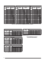
A-CABINET B-CABINET C-CABINET
CFM
Switch
Number
Nominal
Capacity
CFM
Switch
Number
Nominal
Capacity
CFM
Switch
Number
Nominal
Capacity
1 2 3 4 1.5 2 2.5 3 1 2 3 4 1.5 2 2.5 3 3.5 4 1 2 3 4 3 3.5 4 5
540 0 0 0 1 720 0 0 0 1 1075 0 0 0 1
600 0 0 0 0 800 0 0 0 0 1135 1 0 0 1
660 0 0 1 0 850 1 0 0 1 1225 0 0 0 0
715 1 0 0 1 880 0 0 1 0 1295 1 0 0 0
790 1 0 0 0 945 1 0 0 0 1380 0 0 1 0
870 1 0 1 0 1040 1 0 1 0 1460 1 0 1 0
915 0 1 0 1 1085 0 1 0 1 1525 0 1 0 1
955 1 1 0 1 1140 1 1 0 1 1625 1 1 0 1
1015 0 1 0 0 1205 0 1 0 0 1740 0 1 0 0
1060 0 1 1 0 1265 1 1 0 0 1860 1 1 0 0
1075 1 1 0 0 1325 0 1 1 0 1960 0 1 1 0
1165 1 1 1 0 1390 1 1 1 0 2090 1 1 1 0
Table 6. Air Flow Selection for MB6VM Variable Speed Models
A-CABINET
Nominal
KW
CFM
Switch Number
12345678
0-5 700 0 0
6-9 800 1 0
10-14 950 0 1
15 1100 1 1
B-CABINET
Nominal
KW
CFM
Switch Number
12345678
0-5 700 0 0
6-10 800 1 0
11-15 950 0 1
16-20 110 1 1
C-CABINET
Nominal
KW
CFM
Switch Number
12345678
0-9 700 0 0
10-14 950 1 0
15-20 1100 0 1
21-30 1500 1 1
Table 7. MB6VM Minimum Electric Heat Air Flow
Delay
Description
Switch Number
12345678
Delay A 0 0
Delay B 0 1
No Delay 1 0
De-Hum 1 1
NOTE: 0=Off, 1= On
Table 8. MB6VM Delay Settings
(All Variable Speed Models)
Page is loading ...
Page is loading ...
Page is loading ...
Page is loading ...
Page is loading ...
Page is loading ...
Page is loading ...
Page is loading ...
-
 1
1
-
 2
2
-
 3
3
-
 4
4
-
 5
5
-
 6
6
-
 7
7
-
 8
8
-
 9
9
-
 10
10
-
 11
11
-
 12
12
-
 13
13
-
 14
14
-
 15
15
-
 16
16
-
 17
17
-
 18
18
-
 19
19
-
 20
20
-
 21
21
-
 22
22
-
 23
23
-
 24
24
-
 25
25
-
 26
26
-
 27
27
-
 28
28


Westinghouse MB6(B,E,V)M Installation guide
- Type
- Installation guide
Ask a question and I''ll find the answer in the document
Finding information in a document is now easier with AI
Related papers
-
Broan PAH2BM Product information
-
-
-
Broan H6HK Electric Heater Kit Product information
-
Westinghouse H3HK Product information
-
-
Westinghouse B6BMM0 Product information
-
Broan Indoor Air Handler Variable Speed Conversion Kit Installation guide
-
Broan Q4SE Installation guide
-
Broan MB6(B,E,V)M Installation guide
Other documents
-
Ventamatic XXFIRESTAT Operating instructions
-
Gibson GB5BM Product information
-
 International Controls & Measure ACH060 Installation guide
-
ICM Controls ICM256 Application/Install Guide
-
 Climate Master TAH038CGSMBS User guide
-
ICP PA5530AKA2 Owner's manual
-
COMFORT-AIRE MM9E080C16MP11-CY Operating instructions
-
Johnson Controls MG9S*MP Installation guide
-
Reznor JT4BE048KA Operating instructions
-
Winchester WMP36-18 Installation guide

