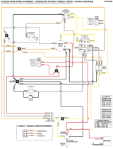
3-2
Z Master 7500-D Series Service Manual
March 2018 - Digital Edition
Table of Contents
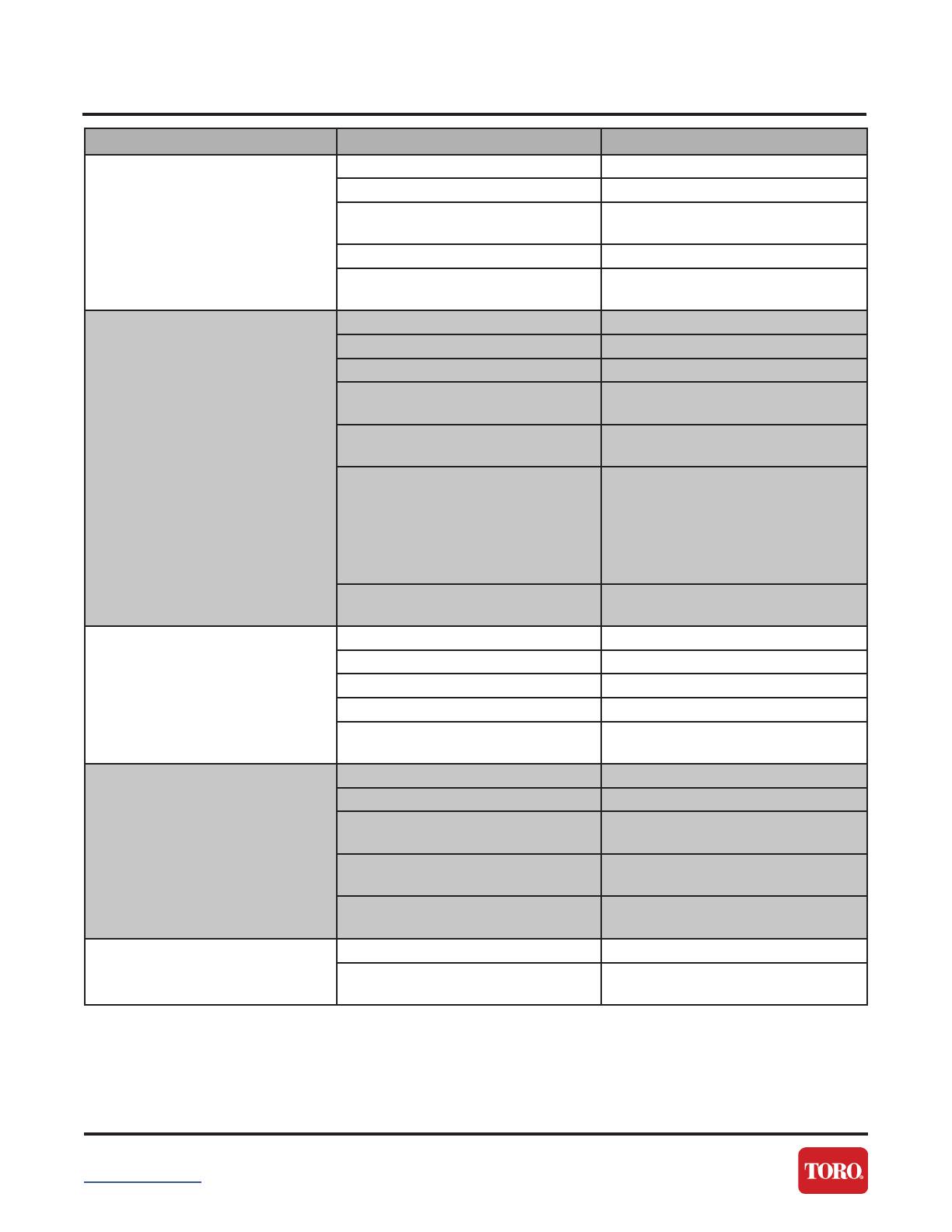
TROUBLESHOOTING
Problem Possible Cause Next Step...
The starter does not crank The parking brake is not engaged Set the parking brake
The battery is dead Charge the battery
The electrical connections are
corroded or loose
Check the electrical connects for
good contact
The fuse is blown Replace the fuse
The relay or ignition switch is worn
or damaged
Test and replace faulty relay or
ignition switch
The engine does not start,
starts hard, or fails to keep
running
The fuel tank is empty Fill the fuel tank
The oil level in the crankcase is low Add oil to the crankcase
There is dirt in the fuel filter Replace the fuel filter
There is dirt, water, or stale fuel in
the fuel system
Clean and flush the fuel system
The air cleaner is dirty Clean or replace the air cleaner
element
The electrical connections are
corroded, loose, or damaged
Check the electrical connections for
good contact
Clean the connector terminals
thoroughly with electrical-contact
cleaner, apply dielectric grease, and
make the appropriate connections
The relay or switch is worn or
damaged
Test and replace faulty relay or
switch
Engine loses power The engine load is excessive Reduce the ground speed
The air cleaner is dirty Clean the air cleaner element
The oil level in the crankcase is low Add oil to the crankcase
There is dirt in the fuel filter Replace the fuel filter
There is dirt, water, or stale fuel in
the fuel system
Clean and flush the fuel system
The engine overheats The engine load is excessive Reduce the ground speed
The oil level in the crankcase is low Add oil to the crankcase
The cooling system is contaminated/
low
Inspect coolant for proper level and
condition. Correct as needed.
The cooling fan/belt is damaged. Ensure the condition of the both the
fan and belt
The radiator is plugged/damaged. Inspect radiator fins for plugging
bends, repair as needed
The unit pulls to the left or right
(with levers fully forward)
The tracking needs adjustment Adjust the tracking
The rear tire pressure is unmatched. Check and adjust the tire pressure
to 124 kPa (18 psi)