Page is loading ...

TAP6014
Arroscia 4 in 1 Hot Water Tap
11-19
Guarantee (UK only):
Your tap has the benefit of a comprehensive manufacturer’s guarantee, details of which are shown on your Proof of Purchase
Document. Any claim during the period of the guarantee must be accompanied by the Proof of Purchase. The product must be
correctly installed and operated in accordance with the manufacturer’s instructions and used for normal domestic purposes. This
guarantee does not cover accidental damage, misuse or alterations which are likely to affect the product. The guarantee is invalid if the
product is tampered with, or repaired by any unauthorized person. The guarantee in no way affects your statutory or legal rights.
Care Instructions for your Kitchen Sink Mixer:
To maintain the appearance of this tap, ensure that it is regularly cleaned only using a clean, soft damp cloth. A solution of warm water
and a mild liquid detergent may be used where necessary, and then the fitting rinsed thoroughly and wiped dry. Any other cleaning
action will invalidate your warranty.
Abrasive cleaners, scouring cleaners and acidic cleaners must not be used under any circumstances. Avoid contact with all solvents
(including chlorinated solvents, ketones or acetones as these may result in surface deterioration or etching). Also avoid contact with
any harsh household chemicals such as oven cleaners, drain cleaners, rust removers, paint strippers and toilet bowl cleaners, bar
keepers friend or Brasso.
Where the tap has a removable aerator on the spout exit it can be removed and cleaned periodically to maintain optimum flow
performance.
Important Technical Data:
Minimum operating pressure (hot): 0.5 bar
Minimum operating pressure (cold): 1.5 bar
Maximum operating pressure: 5.5 bar*
Maximum domestic hot water temperature: 70°C*
Flow characteristics: Domestic Hot, Cold &
Filtered share outer single flow spout.
Boiled water: Through centre spout channel.
Recommended domestic hot water temperature: 46°C
*If these temperatures or pressures are exceeded, even for short periods, damage can result. In these instances a thermostatic mixing
or pressure reducing valve should be installed.
This product is manufactured in accordance with recognised European standards. Please ensure that your kitchen mixer is fitted in
accordance with Local Water Byelaws. Where hot and cold water mix within the tap, then suitable non return (check) valves
should be installed to both the hot and cold supplies to prevent backflow, a preinstalled non return valve on the cold supply flexi
hose (F1) is already supplied (see instructions key).
Hot and cold supply pressures should be as closely balanced as possible for best results. Supply pipes should maintain the maximum
diameter until immediately before the fitting. The differential between the hot and cold water supply temperatures should be sufficient to
allow correct mixing function.
These installation guidelines have been prepared for your direction and you must exercise due care at all times. We do not accept
responsibility for problems that may occur through improper installation. Whilst assembling the tap take care not to accidentally loosen
any factory fixed assemblies.
This tap has been 100% assembly tested; therefore you may expect a small residual amount of water to remain in the tap when
delivered. Any water marks can be removed using the above care advice.
Installation Preparation
⚠Before installing the new mixer it is essential that you thoroughly flush through the supply pipes in order to remove any
remaining solder, swarf or impurities from your system. Failure to carry out this simple procedure could cause problems or
damage to the workings of the mixertap or boiler.
We recommend installing particle filters (not shown) and isolation valves (G1) to both the hot and cold feed pipes in an
accessible position. This will help to prevent premature failure of the valves and ease any future maintenance.
Ensure you have suitable domestic hot and cold water pressure before installing this product (see technical data for more
information).
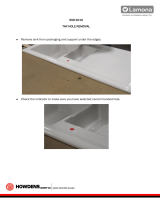
All parts should be removed from their packaging and inspected for any transport damage and that all parts are present prior to
installation.
Shut off your water heating system and ensure that your mains stopcock is closed. Open the lowest hot and cold taps in the house and
allow the water to run until fully stopped.
If replacing an existing tap, remove the tap & clean the end of the feed pipes using wire wool, the tap hole area should be free from
dirt and sealant. Loosely position the tap and tail pipes to check if any alteration to the existing pipework is required, if this
is the case do this now.

Parts and Contents
Key
Description
Qty
A1
Mixer tap
1
A2
Base plinth
1
A3
Base plinth seal
1
A4
Sink or worktop (max. 50mm)
0
A5
White triangular plate (for use
with steel sinks only)
1
A6
Lower gasket
1
A7
Metal horseshoe
1
A8
Fixing stud
1
A9
Fixing nut
1
B1
Cold filtered (from tap to boiler)
flexible hose (M8 x 3/8”F),
includes captive seal
1
B2
3/8” M x ¼”F brass adaptor
1
B3
¼” NPT M x ¼” pushfit
1
B4
¼” outside diameter plastic pipe
1**
C1
Cold filtered (from filter to tap)
blue banded flexible hose (M8 x
3/8”F), includes captive seal
1
C2
3/8” M x ¼”F brass adaptor
1
C3
¼” NPT M x ¼” pushfit
1
C4
¼” outside diameter plastic pipe
1**
C5
Filter bracket
1
C6
Filter bracket screw
1
C7
Filter cartridge
1
C8
¼” outside diameter plastic pipe
1**
C9
¾” BSPF x ¼” pushfit adaptor
1
D1
Steaming hot water (from boiler
to tap) “110°” red labelled
flexible hose. M8 x 3/8”F
1
D2
3/8” fibre seal
1
E1
Domestic hot in (from mains
feed) red banded flexible hose
M10 x ½”BSPM (15mm)
1
F1
Domestic cold in (from mains
feed) blue banded flexible hose
M10 x ½”BSPM (15mm)
1
F2
Non return valve (factory fitted
into flexible hose F1)
1
F3
15mm olive
0
F4
15mm nut
0
F5
15mm pipe
0
G1
15mm isolation valve
0
G2
15mm olive
0
G3
15mm nut
0
G4
15mm pipe
0
G5
15mm nut
2
G6
15mm olive
2
G7
½” x ½” x 3/4” isolating tee valve
1
**Part supplied with boiler pack, cut to form
required lengths to and from filter and boiler,
for the boiler parts list and connections please
refer to the instructions supplied with the
boiler for more detail.

Tap & Filter installation
This diagram shows the
view of the base of the tap
(A1) with the 98°C water
handle to the left of the
body.
⚠ YOU MUST
CAREFULLY
RESPECT THE
INLETS AND
OUTLETS AS
SHOWN
Install the tap:
1. Screw the fixing stud (A8) into base of tap (A1) as shown on the diagram.
2. Place the base plinth (A2) and base plinth seal (A3) onto the base of the tap (A1).
3. Hand tighten the domestic hot in flexible hose (E1) as shown in the diagram.
4. Hand tighten the domestic cold in flexible hose (F1) as shown in the diagram.
5. Hand tighten the filtered cold in flexible hose (C1) as shown in the diagram.
⚠
TAKE CARE NOT TO
INVERT (C1) & (B1). DOING
SO WILL RESULT IN NO
FILTERED WATER
6. Hand tighten the filtered cold out flexible hose (B1) as shown in the diagram.
7. Hand tighten the 110° rated steaming hot flexible hose (D1) into the centre inlet as shown on the diagram.
8. Place the tap (A1-A3) centrally and straight to the tap hole, passing the fixing stud (A8), flexi hoses (B1, C1, D1, E1 & F1)
through the tap hole.
9. Pass the lower gasket (A6) then the metal horseshoe (A7) over the fixing stud (A8). Note: only if the tap is to be fitted to a
stainless steel sink then the white triangular plate (A5) can be fitted where shown to improve the stability of the tap.
10. Using a 13mm box spanner or small adjustable spanner tighten fixing nut (A9) onto the fixing stud (A8).
11. Screw pushfit (B3) into brass adaptor (B2) and pushfit (C3) into brass adaptor (C2)
⚠ We recommend using PTFE tape (do not use sealing compound) on the thread of the pushfit fittings to
make a good seal without applying excessive force (which may damage the plastic pushfit if overtightened).
12. Screw pushfit (B3) and adaptor (B2) into the filtered cold out flexible hose (B1).
13. Screw pushfit (C3) and adaptor (C2) into the filtered cold in flexible hose (C1).
14. Connect the domestic hot water flexible hose (E1) to the hot water isolation valve (G1) using a section of 15mm pipe (G4) and
compression nuts (G3) and olives (G2).
15. Arrange and install the domestic cold in isolation valve (G1) and a stub of 15mm pipe (G4) using 15mm compression nut (G3)
and olive (G2).
16. Fix the ½” x ½” x 3/4” isolating tee valve (G7) to the cold water feed pipe (G4) using 15mm compression nut (G5) and olive (G6).
Ensure to arrange the blue lever on the Tee so it is easily accessible for your customer.
⚠ If your customer has a water softener installed you must attach the isolating Tee valve (G7) to an
unsoftened cold water source, the cold water in flexible hose (F1) can however connect to either a softened or
unsoftened water source.
17. Connect the domestic cold in flexible hose (F1) to the ½” x ½” x 3/4” isolating tee valve (G7) using 15mm compression nut (G5),
olive (G6) and a section of 15mm pipe (F5).
18. Screw the ¾” BSP x ¼” pushfit (C9) onto the three-way valve (G7) ¾” male output.

Install the Filter:
1. Find a suitable place to mount the filter cartridge (C7) under the sink, it must be mounted vertically, easily accessible (to be
changed periodically), away from any heat source or electrical connections and close enough not to exceed the available length of
the ¼” plastic pipe (B4,C4,C8) supplied to reach the between the tap, filter and boiler (place the boiler temporarily to help judge the
required lengths of ¼” plastic pipe).
2. Using the self-tapping screw (C6) securely fix the filter bracket (C5) to the cabinet wall.
3. Write the installation date onto the filter label in permanent pen.
4. Clip the filter cartridge (C7) into the bracket (C5) as shown.
You must respect the direction of flow as indicated on the filter cartridge (C7).
5. Measure and then cut required length of ¼” pipe (C4) to connect pushfit (C3) to the filter cartridge (C7) outlet, allow a small amount
of extra length to make it easier to change the filter.
6. Firmly push connect the ¼” pipe (C4) between pushfit (C3) and filter cartridge outlet (C7).
7. Measure and then cut required length of ¼” pipe (C8) to connect pushfit (C9) to the filter cartridge (C7) inlet, allow a small amount
of extra length to make it easier to change the filter.
8. Firmly push connect the ¼” pipe (C8) between pushfit (C9) and filter cartridge inlet (C7).
9. Firmly push connect the remaining ¼” pipe (B4) into pushfit (B3).
After installation of the tap and filter is complete
1. Ensure that the isolating Tee valve (G7) is in the closed position as shown.
2. Close (turn off) both handles on the tap.
3. Reconne
ct the domestic hot and cold water supplies and open hot and cold isolatio
valves (G1). As the system starts to refill, check carefully all new water connections
for leaks. After the product installation is complete we recommend you recheck for
any slower leaks.
⚠ It is normal for new filter cartridges to lose a small amount of loose carbon when first used and will dissipate with flushing, whilst
harmless to consume if the carbon particles are not flushed prior to connection to the boiler they may partly block the boiler and reduce the
flow rate. You must flush the filter for at least 2 litres with cold water or until the water become clear (without black carbon
particles).
4. Ensure that the isolating Tee valve (G7) is in the open position as shown.
5. Place the ¼” pipe (B4) from the tap into a bowl or bucket.
6. Turn on the 98°C forwards handle fully, keep the lever open until all air is expelled
and cold (filtered) water exits the ¼” pipe (B4) into the bowl, flush a minimum of a
further 2 litres of cold (filtered) water through the ¼” pipe (B4). You may notice a
discolouration to the water at first, this is loose carbon particles from the filter it is
normal, harmless and will pass with flushing. Continue to flush the filter until the
water runs clear. Once complete turn off the 98°C handle.
19. You can adjust the flow rate of the filtered water going to both the tap and boiler by adjusting the position of the blue lever on the
isolating Tee valve (G7), you should aim for approximately 1-2 litres for both cold filtered and boiled filtered water.
20. Please refer to ‘PROBOIL.2X User & Installation Guide’ for the next steps on how to install the boiler and connect the tap
and filter.

Using the product
Your tap can dispense 4 types of water:
• Cold (filtered) water – This is delivered when the left side handle is rotated backwards up to a maximum of apx. 45° (Fig 1).
• Hot (boiled & filtered) water Fully push the left side handle lever down (Fig 2.) and then simultaneously turn the handle forwards
(Fig 3.), the further forwards the lever is turned the greater the flow up to a maximum of apx. 45°. It is normal for the hot water to
take a moment to start and stop dispensing as the water empties from the product after use.
• Hot & Cold (domestic) water – Mixed water is delivered when the right-side handle is tilted right (Fig. 4). With the handle tilted
Cold water is delivered when pushed backwards, and Hot is delivered when pulled forwards.
Fig 1.
Fig 2.
Fig 3.
Fig 4.
Each time the product is used you should flush a small amount of boiled water through before use, typically this can be used to preheat
your cup, if unused for extended periods then flush the product a longer time.
⚠ WARNING: THIS APPLIANCE CAN BE USED BY CHILDREN AGED FROM 8 YEARS AND ABOVE
AND PERSONS WITH REDUCED PHYSICAL, SENSORY OR MENTAL CAPABILITIES OR LACK OF
EXPERIENCE AND KNOWLEDGE ONLY IF THEY HAVE BEEN GIVEN SUPERVISION OR INSTRUCTION
CONCERNING USE OF THE APPLIANCE IN A SAFE WAY AND HAVE UNDERSTAND THE HAZARDS
INVOLVED. CHILDREN SHALL NOT PLAY WITH THE APPLIANCE. CLEANING AND USER
MAINTENANCE SHALL NOT BE MADE BY CHILDREN. ALL WIRING AND INSTALLATION MUST BE
SUPERVISED BY A SUITABLY QUALIFIED PERSON.
⚠ Do not add to, exchange or modify any component of the boiler or mixer tap, only genuine parts must be
used. The spout exit or any part of the system must not include any additional third party adaptors,
components or connections that will add resistance or modify the system.
⚠ The installation should be periodically checked for damage, if the property is left unattended for a
prolonged period we recommend isolating water supplies and switching off the boiler at the mains socket, on
reconnection flush thoroughly.
Please leave these instructions for your customer.
ref/Arroscia4in1HotWaterTapv1
/