Page is loading ...

© LINDY ELECTRONICS LIMITED & LINDY-ELEKTRONIK GMBH - FIRST EDITION (FEB 2016)
AV Converter Switch
User Manual English
No. 38273
www.lindy.com

User Manual
Introduction
Thank you for purchasing the LINDY AV Conversion Switch. Featuring 8 AV inputs which can be
converted and scaled to resolutions up to Full HD 1080p to be output via 3 outputs, this Switch is an
ideal addition to any meeting or conference room, lecture hall or auditorium. The Switch features
configuration and control via RS-232, Telnet, Web GUI and IR making it simple to integrate within
automated installations. For added flexibility the Switch can be used with LINDY’s range of AV
Extenders, to reach remote displays and projectors.
Package Contents
AV Conversion Switch
IR Remote Control with 2 x AAA Alkaline batteries
IR Extender Cable
VGA to 3 x RCA (RGB) Adapter cable
Mounting Brackets
Multi Country Power Supply with UK, EU, US & AUS adapters +5V DC 3A
LINDY Quick Install Guide
Features
Converts and Scales 8 AV Inputs to resolutions up to Full HD 1080p
Simultaneous video output via VGA and 2 x HDMI
Simultaneous audio output via Analogue 3.5mm and Digital Coax
Supports Analogue Audio Embedding for HDMI Inputs
Controlled by IR, OSD, RS-232, Telnet and Web GUI
Specification
Supports DAC & ADC audio/video signal conversion
Video output scaling from 640x480 up to Full HD 1920x1080p 60Hz
Scaling types: Overscan, Full, Follow Input, Pan Scan, Letter Box, Under 2 & Under 1
Supports Frame Rate Conversion
Supports 3D de-interlace, noise reduction and 3D comb filter
Controllable via IR, OSD, RS232, Telnet and Web GUI
Input Ports:
3 x HDMI + 3.5mm Audio
3 x VGA + 3.5mm Audio
Component Video + 2 x RCA Audio
Composite Video + 2 x RCA Audio
Output Ports:
2 x HDMI
VGA
3.5mm Analogue Audio
Coaxial digital audio
Control Ports:
RJ45 – Telnet/IP
9 Way Female – RS232
Simultaneous output from HDMI & VGA ports Coaxial and 3.5mm ports
EDID & HDCP compatible
Operating temperature 0
0
C – 40
0
C
Storage Temperature -20
0
C – 60
0
C
Relative humidity: 20 – 90% RH (non condensing)
Dimensions: 432 x 183 x 47mm (W x D x H)

User Manual
Installation
To begin using the Switch simply connect your AV source devices to the corresponding input ports of the
Switch using standard male/male cable, and then connect the outputs of the Switch to your display
equipment again using standard male/male cables as required. The VGA output of the Switch can also
be used with Component video display using the supplied VGA/RGB adapter cable. Once all sources
and displays have been connected attach the power supply and turn the Switch on using the Power
switch on the rear of the unit and then the power button on the front of the unit.
You can now switch between the inputs using the input selections buttons on the front of the unit or by
using the corresponding buttons on the supplied IR remote control. To enter the On Screen Display
(OSD) press the Menu button and use the + and - buttons to navigate the menus, using the Enter button
to make your selections. For further information on the options available via the OSD please refer to the
OSD Menu section of this manual.
In addition to the OSD the Switch can also be controlled using its Web GUI or RS-232/Telnet
Commands. The required configuration and available commands for this control options are explained
later in this manual.
Overview
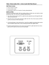
Front
1. Power Button and LED: Press this button to turn the Switch on or to set it to standby mode. Please
Note: There is a power switch on the rear of the unit which can be used to turn the Switch off
completely, the front Power button will only function when the rear switch is set to On.
2. IR Receiver Window: Receives only the IR signal from the supplied remote control
3. Input Buttons and LEDs: Press these buttons to switch directly to the required source. An LED will
illuminate to indicate the selected input source.
4. Menu: Press this button to enter the On Screen Display (OSD) menu.
5. Plus/Minus (−/+) Buttons: Press these buttons to navigate down and up in the OSD menu.
6. Enter: Press this button to confirm the selection in the OSD menu. Please Note: Press this button
simultaneously with the '+' (plus) button to instantly switch the output to XGA resolution or with the '−'
(minus) button to instantly switch the output to 720p resolution.
1
2
3
4
5
6

User Manual
Rear
1. IR In: Connect the supplied IR extender cable to receive the IR signal from the supplied IR remote.
Ensure that the IR remote is within the direct line-of-sight of the IR extender.
2. RS-232: Connect to a PC/Laptop or RS-232 control system to use RS-232 commands to control the
device.
3. Output:
a) HDMI 1/2: Connect to an HDMI display or AV Receiver for video and/or audio output.
b) PC/HD: Connect to a monitor/display for video output. For HD (Component) output, use the supplied
D-Sub 9pin to 3 RCA adapter cable for HD resolutions from 480p – 1080p.
Please Note: When the selected HDMI input source signal has HDCP content the VGA/Component
output will not display any image.
c) COAX: Connect to an amplifier or active speakers for audio output in digital format.
Please Note: When the input audio source signal is in bitstream format and the AUDIO SOURCE setting
is set to AUTO in the OSD menu, the coaxial output will pass-through the input audio signal including
compatible surround sound formats.
d) AUDIO: Connect to an amplifier or active speakers for analogue audio output in stereo format.
4. Input:
a) HDMI 1/2/3: Connect to HDMI sources such as Blu-ray/DVD player for both video and audio signal
conversion.
b) PC 1/2/3: Connect to a PC/Laptop source for video signal input with a 15pin VGA cable.
c) 3.5mm Mini-jacks: Connect to source's L/R output with 3.5mm mini-jack for audio signal conversion.
Please Note: For HDMI signals you can select in the OSD Menu whether you require audio from the
HDMI (AUTO) or from the analogue audio inputs (EXT)
d) YCbCr/YPbPr + L/R: Connect to source equipment such as a DVD player for both video and audio
signal conversion.
e) CV + L/R: Connect to a composite video source such as a video/DVD player for both video and audio
signal conversion.
5. Control: This port is the link for Telnet or Web GUI controls, connect to an active Ethernet link with an
RJ45 terminated cable.
6. Power: Switch this power toggle to turn on and activate the device or turn off to shut it down.
7. DC 5V: Connect the supplied power adapter to the Switch and plug it into an AC wall outlet.
1
2
5
6
7
4
3

User Manual
RS-232, Telnet & On Screen Display
RS-232 Settings
Presentation Switch
Remote Control
PIN
Assignment
PIN
Assignment
Baud Rate
19200bps
1
NC
1
NC
Data Bit
8
2
Tx
2
Rx
Parity
None
3
Rx
3
Tx
Flow Control
None
4
NC
4
NC
Stop Bit
1
5
GND
5
GND
6
NC
6
NC
7
NC
7
NC
8
NC
8
NC
9
NC
9
NC
Telnet Settings
Before attempting to use telnet control, please ensure that both the Switch (via the CONTROL port) and
the PC/Laptop are connected to the same active network.
Open a Command Prompt on your computer type telnet, then a space, then the IP address of the
Switch (default is 192.168.0.1), then another space, then 23 and finally press Enter. This will bring up the
Telnet interface for the Switch. Type ? to list all the available commands, please refer to the RS-232 &
Telnet Commands section of this manual for a description of each command.
RS-232 and Telnet Commands
Commands will be not executed unless followed with a carriage return (0x0D) and LF (Line Feed)
Commands are not case sensitive.
Resolutions 0 – 13 are RGB encoded, 14 – 21 are YUV encoded
Command
Description
S POWER 0/1
0 = OFF, 1 = ON
R POWER
Reports the numeric value of power setting (as above)
S SOURCE 1 – 8
1 = HDMI 1, 2 = HDMI 2, 3 = HDMI 3, 4 = YPbPr,
5=CVIDEO, 6 = PC 1, 7 = PC 2, 8 = PC 3
R SOURCE
Reports the numeric value of SOURCE setting as above
S OUTPUT 0 – 21
0=640×480
1=800×600
2=1024×768
3=1280x768
4=1360×768
4=1280×720
6=1280×800
7=1280×1024
8=1440×900
9=1400×1050
10=1680×1050
11=1600×1200
12=1920×1080
13=1920×1200
14=480p
15=720p@60
16=1080i@60
17=1080p@60
18=576p
19=720p@50
20=1080i@50
21=1080p@50
R OUTPUT
Reports the numeric value of OUTPUT setting as above

User Manual
Command
Description
S SIZE 0 – 6
0=OVERSCAN
1=FULL
2=FOLLOW INPUT
3=PAN SCAN
4=LETTER BOX
5=UNDER 2
6=UNDER 1
R SIZE
Reports the numeric value of SIZE setting as above
S INPUT HDCP 0/1
0 = ON, 1 = OFF
R INPUT HDCP
Apple only. Reports the numeric value of HDCP setting as above
S SYNCSHIFT 0/1
0 = ON, 1 = OFF
R SYNCSHIFT
Reports the numeric value of SYNCSHIFT setting as above
S CONTRAST 0 – 60
Set the numeric value for CONTRAST from 0 – 60
R CONTRAST
Reports the numeric value of CONTRAST setting as above
S BRIGHTNESS 0 – 60
Set the numeric value for BRIGHTNESS from 0 – 60
R BRIGHTNESS
Reports the numeric value of BRIGHTNESS setting as above
S HUE 0 – 60
Set the numeric value for HUE from 0 – 60
R HUE
Reports the numeric value of HUE setting as above
S SATURATION 0 – 60
Set the numeric value for SATURATION from 0 – 60
R SATURATION
Reports the numeric value of SATURATION setting as above
S SHARPNESS 0 – 30
Set the numeric value for SHARPNESS from 0 – 30
R SHARPNESS
Reports the numeric value of SHARPNESS setting as above
S NR 0 – 3
0=OFF, 1=LOW, 2=MIDDLE, 3=HIGH
R NR
Reports the numeric value of NOISE REDUCTION setting as above
S AUDIO VOLUME 0 – 100
Set the numeric value for VOLUME from 0 – 100
R AUDIO VOLUME
Reports the numeric value of VOLUME setting as above
S AUDIO DELAY 0 – 3
0=OFF, 1=40ms, 2=110ms, 3=150ms
R AUDIO DELAY
Reports the numeric value of AUDIO DELAY setting as above
S AUDIO MUTE 0/1
0=ON, 1=OFF
R AUDIO MUTE
Reports the numeric value of AUDIO MUTE setting as above
S HDMI AUDIO 0/1
0=AUTO, 1=EXT
R HDMI AUDIO
Reports the numeric value of HDMI AUDIO setting as above
S KEY LOCK 0/1
0=ENABLE, 1=DISABLE
R KEY LOCK
Reports the numeric value of KEY LOCK setting as above
S FREERUNCOLOR 0/1
0=BLACK, 1=BLUE
R FREERUNCOLOR
Reports the numeric value of FREERUNCOLOR setting as above
S RESET 1
Resets the Switch to default values
PORT 0 – 8
0=LAST MEMORY, 1 = HDMI 1, 2 = HDMI 2, 3 = HDMI 3,
4 = YPbPr, 5=CVIDEO, 6 = PC 1, 7 = PC 2, 8 = PC 3
ST
Checks the Firmware version
VOL +
Raises the volume level (VOLUME * IS SET)
VOL -
Lowers the volume level (VOLUME * IS SET)
QUIT
Exit (Telnet Only)

User Manual
OSD Menu
1
st
Layer
2
nd
Layer
3
rd
Layer
4
th
Layer
DISPLAY
OUTPUT
640X480 60
800x600 60
1024x768 60
1280x768 60
1360x768 60
1280x720 60
1280x800 60
1280x1024 60
1440x900 60
1400x1050 60
1680x1050 60
1600x1200 60
1920x1080 60
1920x1200 60
1280X720P 60
1920X1080I 60
1920X1080P 60
720X576P 50
1280X720P 50
1920X1080i 50
1920X1080P 50
SIZE
OVER SCAN
FULL
FOLLOW INPUT
PAN SCAN
LETTER BOX
UNDER 2
UNDER 1
MODE INFO
ON
INFO
OFF
INPUT HDCP (HDMI Only)
OFF
ON
PC (PC Only)
AUTO SETUP
H_POSITION
V_POSITION
PHASE
CLOCK
WXGA/XGA
XGA
WXGA
RESET
TIMING SHIFT
OFF
ON
COLOR
CONTRAST
0 – 60 (30)
BRIGHTNESS
0 – 60 (30)
COLOR
R 0 – 1023 (512)
G 0 – 1023 (512)
B 0 – 1023 (512)
R OFFSET 0 – 1023 (512)

User Manual
1
st
Layer
2
nd
Layer
3
rd
Layer
4
th
Layer
COLOR (Continued)
COLOR (Continued)
G OFFSET 0 – 1023 (512)
B OFFSET 0 – 1023 (512)
HUE
0 – 60
SATURATION
0 – 60
SHARPNESS
0 – 60
NR
OFF
LOW
MIDDLE
HIGH
AUDIO
VOLUME
0 – 100 (100)
DELAY
OFF
40mS
110mS
150mS
SOUND
ON
MUTE
SOURCE (HDMI Only)
1
AUTO
EXT
SETUP
FACTORY RESET
2
KEYLOCK
OFF
ON
POWER SAVE
OFF
ON
IP MODE
DHCP
STATIC
SET STATIC IP
IP ADDRESS
0.0.0.0 – 255.255.255.255
3
SUBNET MASK
0.0.0.0 – 255.255.255.255
4
DEF GATEWAY
0.0.0.0 – 255.255.255.255
5
FREERUN COLOR
BLACK
BLUE
INFORMATION
INPUT
OUTPUT
REVISION
IP ADDRESS
Please Note:
1. When AUDIO SOURCE is set to 'AUTO' if the selected HDMI input port is connected to an HDMI
source, audio signal of the source will be used; if the selected HDMI input port is connected to a DVI
source, audio signal from the 3.5mm socket on top of the selected HDMI input port will be used. When
AUDIO SOURCE is set to 'EXT' only the audio signal from the 3.5mm socket on top of the selected
HDMI input port will be used..
2. The FACTORY RESET option in the OSD menu will only reset part of settings. For a complete reset
of the system, please use the reset button on the remote control.
3. 192.168.0.1 (Default setting).
4. 255.255.255.0 (Default setting).
5. 192.168.0.254 (Default setting).
6. Items in Bold or Brackets are the Factory default settings.

User Manual
Web GUI
On a PC/Laptop that is connected to same active network as the Scaler, open a web browser and type
device's IP address (Default is 192.168.0.1) on the web address entry bar. The browser will bring up the
control page of the Switch (see below for reference).
From the control page it is possible to make the same adjustments to settings as are available through
the OSD, RS-232 and Telnet commands, with the exception of Freerun Color (Background colour used
when no Input is available) which cannot be adjusted via the Web GUI.
Supported Resolutions
Input Resolutions
Input
Resolution
Composite
Video
Component
Video
PC
HDMI
NTSC/PAL
-
-
-
480/576i
-
-
480/576p
-
-
720p@50/60Hz
-
-
1080i@50/60Hz
-
-
1080p@50/60Hz
-
-
VGA@60/72/75Hz
-
-
SVGA@56/60/72/75Hz
-
-
XGA@60/70/75Hz
-
-
SXGA@60/75Hz
-
-
UXGA@60Hz
-
-
1280x800@60Hz
-
-
1680x1050RB@60Hz
-
-
1920x1080@60Hz
-
-
1920x1200RB@60Hz
-
-

Legal Information
CE Certification
This equipment complies with the requirements relating to Electromagnetic Compatibility Standards
EN55022/EN55024 and the further standards cited therein. It must be used with shielded cables only.
It has been manufactured under the scope of RoHS compliance.
CE Konformitätserklärung
Dieses Produkt entspricht den einschlägigen EMV Richtlinien der EU für IT-Equipment und darf nur
zusammen mit abgeschirmten Kabeln verwendet werden.
Diese Geräte wurden unter Berücksichtigung der RoHS Vorgaben hergestellt.
Die formelle Konformitätserklärung können wir Ihnen auf Anforderung zur Verfügung stellen
FCC Certification
This equipment has been tested and found to comply with the limits for a Class B digital device, pursuant
to part 15 of the FCC Rules. These limits are designed to provide reasonable protection against harmful
interference in a residential installation.
Operation is subject to the following two conditions:
1. This device may not cause harmful interference, and
2. This device must accept any interference received, including interference that may cause undesired
operation.
LINDY Herstellergarantie – Hinweis für Kunden in Deutschland
LINDY gewährt für dieses Produkt über die gesetzliche Regelung in Deutschland hinaus eine
zweijährige Herstellergarantie ab Kaufdatum. Die detaillierten Bedingungen dieser Garantie finden Sie
auf der LINDY Website aufgelistet bei den AGBs.
Hersteller / Manufacturer (EU):
LINDY-Elektronik GmbH LINDY Electronics Ltd.
Markircher Str. 20 Sadler Forster Way
68229 Mannheim Teesside Industrial Estate, Thornaby
GERMANY Stockton-on-Tees, TS17 9JY
Email: info@lindy.com United Kingdom
T: 0049 (0)621 470050 postmaster@lindy.co.uk
T: +44 (0) 1642 754000

Legal Information
WEEE (Waste of Electrical and Electronic Equipment),
Recycling of Electronic Products
Europe, United Kingdom
In 2006 the European Union introduced regulations (WEEE) for the collection and recycling of all waste
electrical and electronic equipment. It is no longer allowable to simply throw away electrical and
electronic equipment. Instead, these products must enter the recycling process.
Each individual EU member state has implemented the WEEE regulations into national law in slightly
different ways. Please follow your national law when you want to dispose of any electrical or electronic
products. More details can be obtained from your national WEEE recycling agency.
Germany / Deutschland
Die Europäische Union hat mit der WEEE Direktive Regelungen für die Verschrottung und das Recycling
von Elektro- und Elektronikprodukten geschaffen. Diese wurden im Elektro- und Elektronikgerätegesetz
– ElektroG in deutsches Recht umgesetzt. Dieses Gesetz verbietet das Entsorgen von entsprechenden,
auch alten, Elektro- und Elektronikgeräten über die Hausmülltonne! Diese Geräte müssen den lokalen
Sammelsystemen bzw. örtlichen Sammelstellen zugeführt werden! Dort werden sie kostenlos entgegen
genommen. Die Kosten für den weiteren Recyclingprozess übernimmt die Gesamtheit der
Gerätehersteller.
Batteriehinweis
Dieses Produkt enthält nicht wiederaufladbare Batterien. Es ist verboten leere Batterien und Akkus im
Hausmüll zu entsorgen. Sie können leere Batterien und Altgeräte im Handel oder an den Recyclinghöfen
der Kommunen kostenlos abgeben. Alle so gesammelten Batterien und Akkus werden verwertet. So
lassen sich wertvolle Rohstoffe wieder zurück gewinnen.
France
En 2006, l'union Européenne a introduit la nouvelle réglementation (DEEE) pour le recyclage de tout
équipement électrique et électronique.
Chaque Etat membre de l’ Union Européenne a mis en application la nouvelle réglementation DEEE de
manières légèrement différentes. Veuillez suivre le décret d’application correspondant à l’élimination des
déchets électriques ou électroniques de votre pays.
Italy
Nel 2006 l’unione europea ha introdotto regolamentazioni (WEEE) per la raccolta e il riciclo di
apparecchi elettrici ed elettronici. Non è più consentito semplicemente gettare queste apparecchiature,
devono essere riciclate. Ogni stato membro dell’ EU ha tramutato le direttive WEEE in leggi statali in
varie misure. Fare riferimento alle leggi del proprio Stato quando si dispone di un apparecchio elettrico o
elettronico.
Per ulteriori dettagli fare riferimento alla direttiva WEEE sul riciclaggio del proprio Stato.
LINDY No. 38273
1
st
Edition, February 2016
www.lindy.com
/