Page is loading ...

Users Guide
OMACS3000 – Rev E
Andrew Corporation
Telephone: 708-349-3300 Customer Service, 24 hours:
10500 West 153rd Street FAX (U.S.A.): 1-800-349-5444 U.S.A. • Canada • Mexico: 1-800-255-1479
Orland Park, IL U.S.A. 60462 Internet: http://www.andrew.com U.K.: 0800 250055 • Other Europe: +44 1592 782612
Printed in U.S.A. April 11, 2006 Copyright © 2003 by Andrew Corporation
ACS3000 Antenna
Control System
Antenna Control System with SmarTrack
®
April 11, 2006

11-APR-06 Rev E OMACS3000
2 of 51
List of Figures................................................................................................................................. 4
System Description ........................................................................................................................ 5
Overview ................................................................................................................................. 5
Summary................................................................................................................................. 5
Revision History ...................................................................................................................... 5
System Description ................................................................................................................. 5
Indicators Within the LMKVS-CPU .......................................................................................... 7
MC-2 Description..................................................................................................................... 7
Motherboard Limit/Status Card (LIM-2) ................................................................................... 7
Microprocessor Card (MPU-17)............................................................................................... 7
Dual VFD Motor Drive Card (MD-3)......................................................................................... 8
Resolver To Digital Converter Card (RES-2) ........................................................................... 8
Low Temperature Board.......................................................................................................... 8
Antenna Display Unit (Optional) .............................................................................................. 9
Power/Environmental Description LMKVS-CPU ...................................................................... 9
Power/Environmental Description Beacon Interface................................................................ 9
System Setup............................................................................................................................... 11
Operator’s Computer Setup................................................................................................... 11
Java Plug In Installation......................................................................................................... 11
Operator’s Computer IP Address........................................................................................... 11
LMKVS-CPU IP Setup........................................................................................................... 11
Regional Options Setup......................................................................................................... 12
System Screens ........................................................................................................................... 13
ACS3000 Screens................................................................................................................. 13
Home Screen - System Not Initialized ................................................................................... 13
Home Screen - System Initialized.......................................................................................... 13
Home Screen - Hand Held Connected .................................................................................. 14
Set Time/IP ........................................................................................................................... 15
Initialization Screens ............................................................................................................. 16
Initialization Entry .................................................................................................................. 16
Test Only Password Protection Screen ................................................................................. 17
Pre-Initialization Antenna Setup ............................................................................................ 18
Initialize Site Location............................................................................................................ 19
Visible Satellites Computed................................................................................................... 20
Verify Jog Direction ............................................................................................................... 21
Verify Az and El Hardware Limits .......................................................................................... 22
Verify Pol Hardware Limits .................................................................................................... 23
Single Speed Pol Drive Hardware Limits ............................................................................... 23
Dual Speed Pol Drive Hardware Limits.................................................................................. 24
Select Base Satellite ............................................................................................................. 25
Peak on Base Satellite .......................................................................................................... 26
Automated Set Software Limits ............................................................................................. 29
Enter Beacon Receiver Parameters ...................................................................................... 30
Review Parameters............................................................................................................... 31
Initialization Complete ........................................................................................................... 32
Normal Operational Screens ................................................................................................. 33
Position/Jog........................................................................................................................... 33
Tracking Control.................................................................................................................... 34

11-APR-06 Rev E OMACS3000
3 of 51
Tracking Summary ................................................................................................................ 35
Satellite Table Screens.......................................................................................................... 36
Satellite Table Screen ........................................................................................................... 37
Working Satellite Table Screen ............................................................................................. 38
Satellite Entry Edit................................................................................................................. 39
Logs/Alarms .......................................................................................................................... 40
Log Screen............................................................................................................................ 41
Alarm Screen ........................................................................................................................ 42
Alarm and Events Descriptions.............................................................................................. 42
Update Table......................................................................................................................... 46
Update Software.................................................................................................................... 49

11-APR-06 Rev E OMACS3000
4 of 51
List of Figures
Figure 1: System Diagram.............................................................................................................. 6
Figure 2: LMKVS-CPU Admin Application .................................................................................... 12
Figure 3: Home Screen - System Is Not Initialized........................................................................ 13
Figure 4: Home Screen - System Is Initialized .............................................................................. 14
Figure 5: Home Screen - Hand Held Controller Connected .......................................................... 15
Figure 6: Set Time Screen............................................................................................................ 16
Figure 7: Initialization Entry Screen .............................................................................................. 17
Figure 8: Test Only Password Screen .......................................................................................... 18
Figure 9: Pre-Initialization Antenna Setup.................................................................................... 19
Figure 10: Limits Verification Warning ......................................................................................... 19
Figure 11: Initialize Site Location Screen...................................................................................... 20
Figure 12: Visible Satellites Computed Screen............................................................................. 21
Figure 13: Satellite Table Downloaded to PC Popup Window....................................................... 21
Figure 14: Verify Jog Direction Screen ......................................................................................... 22
Figure 15: Verify Hardware Limits Screen .................................................................................... 23
Figure 16: Single Speed Pol Hardware Limits Screen .................................................................. 24
Figure 17: Dual Speed Pol Hardware Limits Screen..................................................................... 25
Figure 18: Select Base Satellite Screen........................................................................................ 26
Figure 19: Peak on Base Satellite Screen .................................................................................... 28
Figure 20: Automated Set Software Limits Screen ....................................................................... 29
Figure 21: Validate Automated Software Limits ............................................................................ 30
Figure 22: Enter Tracking Parameters Screen.............................................................................. 31
Figure 23: Review Parameters Screen......................................................................................... 32
Figure 24: Initialization Complete Screen ..................................................................................... 33
Figure 25: Position/Jog Screen..................................................................................................... 34
Figure 26: Track Control Screen................................................................................................... 36
Figure 27: Satellite Table Button Right Click Option ..................................................................... 37
Figure 28: Satellite Table Screen.................................................................................................. 38
Figure 29: Working Satellite Table Screen.................................................................................... 39
Figure 30: Satellite Table Entry Edit Screen ................................................................................. 40
Figure 31: Log/Alarms Button Right Click Display......................................................................... 41
Figure 32: Logs Screen ................................................................................................................ 42
Figure 33: Alarm Screen............................................................................................................... 46
Figure 34: Celestrack Web Site .................................................................................................... 47
Figure 35: NORAD Data Set......................................................................................................... 48
Figure 36: Update Satellite Table Popup Window......................................................................... 48
Figure 37: Alternate Update Satellite Table Popup Window.......................................................... 49
Figure 38: Update Software Button.............................................................................................. 50
Figure 39: Update Software Confirmation..................................................................................... 50
Figure 40: Update Software Request Denied ............................................................................... 50

11-APR-06 Rev E OMACS3000
5 of 51
System Description
System Description
Overview
The purpose of this User Guide is to describe the steps required to configure, initialize, and operate the
ACS3000 Antenna Control System with SmarTrack®. All parameters are fully programmable and displayed
from a PC running a Web Browser or an existing station monitor and control system.
Summary
The ACS3000 is a complete kit that provides precision three-axis control of all the Andrew earth antennas
from 2.4 to 9.45 meters in size. The ACS3000 features the Andrew SmarTrack® predictive tracking mode
that utilizes a patented Three-Point Peak Algorithm* that saves wear on the antenna motors and jacks.
Another new feature of the ACS 3000 is the VFD (Variable Frequency Drives) that allows the antenna ramp-
up in speed as the antenna is commanded to move to a new target satellite, yet move at low speed when
tracking and peaking up on a satellite. NORAD and INTELSAT program track modes are standard features
included with this product and setup of these modes can be found after the system initialization section.
Revision History
Version Document Description Date
Draft First Draft 17-Aug-01
V 1.0 Updated 21-Nov-01
V 1.1 Updated 18-Jan-02
V 1.2 Updated 28-Feb-02
V 2.0 Updated 5-Jul-04
V 3.0 Updated 20-Feb-06
System Description
The ACS3000 consists of the following equipment:
LMKVS-CPU Outdoor Unit Azimuth and Elevation Motors
Beacon Interface Unit Azimuth and Elevation Resolvers and Limit Switches
Hand Held Controller Electrical Installation Kits
Ethernet Hub Mounting Kits
Optional Equipment
Antenna Display Unit
*U.S. Pat. No. 6657588, France Pat. No. 2852447. Patent pending in the following
countries: Canada, China, Germany, Japan, and United Kingdom.

11-APR-06 Rev E OMACS3000
6 of 51
System Description
Beacon
Receiver
PC with
browser
Ether
net
hub
Beacon
Interface
Box
or
Rack
Mounted
ADU
Motor Control Unit
(MC-2)
Single Board
Computer
(Linux Board)
Handheld
Unit
(Optional)
Fiber
converter
Fiber
converter
Ethernet
10BaseT
Ethernet
10BaseT
RS-232
Multi-protocol
Accessory
power
Local control
Resolvers
Limit
Switches
Motors
HH Protocol
Optional
0 – 10V
sig
strength
DC
UTP
RS-232
SABus protocol
LMKVS-CPU
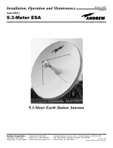
Figure 1: System Diagram
The LMKVS-CPU is the overall manager for the antenna position and satellite signal tracking. The LMKVS-
CPU consists of a Single Board Computer (SBC), a Motor Control Unit (MC-2), Variable Frequency Drives
(VFD) and an Ethernet interface for web browser display and control.
The LMKVS-CPU can also position the antenna via a hand-held unit. Using the handheld unit direction
control buttons, the antenna may be moved in all three axes.
The ACS3000 primary task will be to position the antenna to the received signal of a selected satellite. The
initial setup of the ACS3000 include a full set of all satellites. It builds a subset of those satellites that are
visible to the particular antenna given the antenna latitude and longitude. Using this subset, the operator may
select a specific satellite to point at and may reposition to any of the satellites in the subset at will. In addition
to the primary task, the ACS3000 is able to move to any specified position the operator designates. The
Motor Control Unit will handle the antenna movement rate autonomously once given the coordinates desired
by the operator or as calculated by the SBC during tracking.
The Ethernet connection to the SBC will tie into an Ethernet hub that directly connects to the Beacon
Interface Assembly and browser devices. The Beacon Interface Assembly provides the connection via the
Ethernet hub to the Beacon Receiver data. The data is used to position the antenna on the satellite during
Step Track or SmarTrack® operation The Motor Control Unit connects directly to the VFD's to control the
motors. The Motor Control Unit also connects directly to the limit switches and the resolvers. The MC-2
controls the rate loop used to move the antenna via the hardware and does not need software feedback to
speed up or slow down the movement. The Motor Control Unit communicates with the Single Board
Computer via an internal RS-422 connection.

11-APR-06 Rev E OMACS3000
7 of 51
System Description
Indicators Within the LMKVS-CPU
The MC-2 and the Low Temperature Board contain LED's that indicate certain fault and status conditions.
Within the LMKVS-CPU the MC-2 is designated A1 and the Low Temperature Board is designated A5.
MC-2 Description
The MC-2 Motor Control Logic Assembly handles feedback from antenna mounted limit switches and
resolvers and provides Variable Frequency Drive (VFD) and motor control for the antenna mounted drive
motors. The MC-2 is a compact card cage based design comprising a motherboard and three vertically
attached daughter cards. Each card including the motherboard provides specific functionality and fault/status
indication. The MC-2 mounts to the LMKVS-CPU main panel by means of four standoffs.
Motherboard Limit/Status Card (LIM-2)
The Motherboard Limit/Status Card handles input power distribution, provides a passive back plane for
daughter cards, and provides for 12 independent limit/status switch inputs. Each limit/status switch input has
an associated LED indicating input logic condition. The LED's are located near the wiring input connectors.
The LIM-2 provides the following indications based on limit/status input conditions:
Indicator Function LED Condition
DS12 Future Illuminated steady RED
DS11 Future Illuminated steady RED
DS10 Maintenance Port Cable Attached Illuminated steady RED
DS9 Handheld Detected Illuminated steady RED
DS8 Low Temperature Warning Active RED LED Extinguished
DS7 Low EL Status Switch Activated Illuminated steady RED
DS6 POL CCW Limit Switch Activated Illuminated steady RED
DS5 POL CW Limit Switch Activated Illuminated steady RED
DS4 EL Down Limit Switch Activated Illuminated steady RED
DS3 EL Up Limit Switch Activated Illuminated steady RED
DS2 AZ West Limit Switch Activated Illuminated steady RED
DS1 AZ East Limit Switch Activated Illuminated steady RED
DS-1 through DS-4 will blink RED simultaneously when the LIM-2 card has lost the Data Terminal Ready
(DTR) signal with the MPU-17. Additionally, DS-5 through DS-12 will blink RED simultaneously after loss of
good data from the MPU-17 for more than 2 seconds.
Microprocessor Card (MPU-17)
The Microprocessor Card (left most card) is 80C188 based and contains a proprietary programmed EPROM
for storage of motor control logic executable code. The MPU-17 communicates with the LKMVS-CPU Single
Board Computer (SBC) by means of a dedicated RS-422 serial interface.
The MPU-17 provides the following status indicators and controls that are viewable from the face of the card:
DS-1 COM FLT Illuminates steady RED after loss of good data from the SBC for more than 2
seconds.
DS-2 LIM FLT Illuminates steady RED upon communication failure with the LIM-2 card and/or
indicates an internal failure of the LIM-2 card.
DS-3 MC FLT Illuminates steady RED upon communication failure with the MD-3 card and/or
indicates an internal failure of the MD-3 card.
DS-4 RES FLT Illuminates steady RED upon communication failure with the RES-2 card and/or
indicates an internal failure of the RES-2 card.

11-APR-06 Rev E OMACS3000
8 of 51
System Description
DS-5 STOP Illuminates steady YELLOW when the Emergency Stop Switch is depressed.
DS-6 MICRO RESET Illuminates steady RED when MPU-17 microprocessor is in a reset condition. Blinks
RED in a continuous reset condition or buss failure.
DS-7 POWER Illuminates steady GREEN when MC-2 is receiving +/-12 VDC
Dual VFD Motor Drive Card (MD-3)
The Dual VFD Motor Drive Card (center card) handles control, status and fault reporting of the azimuth and
elevation Variable Frequency Drive Units (VFD's). The Dual VFD Motor Drive Card has two fault indicators.
The MD-3 provides the following fault indicators that are viewable from the face of the card:
DS-1 OVERLOAD Illuminates Steady RED when AZ, EL, or both AZ and EL axis motors are drawing
excessive current. A slow RED blink (500ms) indicates loss of communication with
the MPU-17.
DS-2 FAULT Illuminates RED when either VFD is in a fault condition. A slow RED blink (500 ms)
indicates loss of communication with the MPU-17. A fast RED blink (250 ms)
indicates both forward and reverse VFD direction commands are present
simultaneously.
Resolver To Digital Converter Card (RES-2)
The Resolver To Digital (R/D) Converter Card (right most card) is a multiplexed single converter based card
and provides resolver signal to digital bit converter. The RES-2 card accepts three resolver inputs and
outputs the 16 bit converted value of each resolver signal to the MPU-17.
The RES-2 provides the following indicators:
DS-1 EL CEN Illuminates steady YELLOW when the EL resolver is reading center of the R/D
range (±2 degrees). A slow YELLOW blink (500 ms) indicates a loss of
communication with the MPU17. A fast (250 ms) blink indicates a loss of resolver
signal and would likely be caused by the EL resolver not being properly connected
or defective.
DS-2 AZ CEN Illuminates steady YELLOW when the AZ resolver is reading center of the R/D
range (±2 degrees). A slow YELLOW blink (500 ms) indicates a loss of
communication with the MPU17. A fast (250 ms) blink indicates a loss of resolver
signal and would likely be caused by the AZ resolver not being properly connected
or defective.
DS-3 POL CEN Illuminates steady YELLOW when the POL resolver is reading center of the R/D
range (±2 degrees). A slow YELLOW blink (500 ms) indicates a loss of
communication with the MPU17. A fast (250 ms) blink indicates a loss of resolver
signal and would likely be caused by the POL resolver not being properly connected
or defective.
Low Temperature Board
The low temperature board has the following indicators:
DS1 (Yellow) High Temperature. The temperature inside the enclosure is above +50° Celsius.
DS2 (Red) Low Temperature. The temperature inside the enclosure is at 0° Celsius. A warning
is issued. If the temperature fall below -10° Celsius power is removed from the
VFDs and all antenna movement halted. The temperature must rise above -10°
Celsius before power is restored to the VFDs.
DS3 (Green) Power to the low temperature board is within normal limits.

11-APR-06 Rev E OMACS3000
9 of 51
System Description
Antenna Display Unit (Optional)
The Antenna Display Unit is a rack mountable (two rack height) antenna control unit (ADU) that is designed
to provide direct interface to a local area network to provide a remote control graphical user interface (GUI)
for the ACS3000 Antenna Control System. In addition to the rear panel interface connections, the ADU
provides a front panel mounted LCD display, keyboard, momentary action reset switch, power indicator,
summary fault alarm indicator, and display contrast adjustment allowing an alternate method for the operator
to control and determine status of the ACS3000 antenna Control System. The ADU is documented
separately in the Antenna Display Unit Users Guide.
Power/Environmental Description LMKVS-CPU
Operational Temperature: -40 to +50° C
If heater is off internal temperature must be 0° C
before operation can begin
Storage Temperature: -40 to +60° C
Relative Humidity: 0 - 100% Condensing
Enclosure Protection Class: NEMA 4X / IP56
Enclosure Type: EMI Protected Fiberglass
Control Interface Method: Ethernet
Dimensions: 26 1/2" W x 32" H x 14" D
Weight: 88 lbs
Approvals: EN 60950 (CE), EN 61326 Class A UL 60950, FCC
Part 15 Class A
Power: LMKVS-CPU-208
208 - 230 VAC, 60 Amps
3 Phase 50/60 Hz
No Neutral Required, Safety Ground Required
LMKVS-CPU-380
380 - 460 VAC, 30 Amps
3 Phase 50/60 Hz
No Neutral Required, Safety Ground Required
Power/Environmental Description Beacon Interface
Operational Temperature: 0 to +50° C
Storage Temperature: -40 to +60° C
Relative Humidity: 93 - 100% Non-Condensing
Enclosure Type: 1 RU Rack Mount Metal Enclosure
Control Interface Method: Ethernet

11-APR-06 Rev E OMACS3000
10 of 51
System Description
Dimensions: 19" W x 1.75" H x 4" D
Weight: 3 lbs
Approvals: EN 60950 (CE), EN 61326 Class A
UL 60950, FCC Part 15 Class A
Power: 85-250 VAC, 0.35 Amps
1 Phase 50/440 Hz
Neutral Required, Safety Ground Required

11-APR-06 Rev E OMACS3000
11 of 51 System Setup
System Setup
Operator’s Computer Setup
The ACS3000 is controlled from an operator's computer through an Ethernet connection to the LMKVS-CPU.
The LMKVS-CPU may be connected to the operator's computer via a LAN (Local Area Network) or via a
direct connection using an Ethernet crossover cable. A browser such as Internet Explorer or Netscape is
necessary to activate the Java applet that manages the ACS3000 LMKVS-CPU. In order to use a browser to
connect to the LMKVS-CPU, the Java Plug-in application must be installed on the operator's computer.
IMPORTANT NOTE: Minimum system requirement for use of Revision E of ACS3000 software and
Java Plug-in version 1.4.2_05 is Windows 98. Earlier versions of Windows are not supported.
Java Plug In Installation
The Java Plug-in application is available from Andrew and is installed from a CD delivered with the LMKVS-
CPU. After the file is loaded to the operator's computer, execute the program to install the current version.
The current version of the Java Plug-in program is j2re-1_4_2_05-windows-i586-p.exe. Execute this program
and follow the setup options. Once the program is installed, the operator must replace the java.policy file
that was created by the installation with the java.policy file available on the CD delivered by Andrew. The
new java.policy file must be copied over the java.policy file in the directory C:\Program Files\ Java\
j2re1.4.2_05\lib\security.
Operator’s Computer IP Address
The LMKVS-CPU and operator's computer IP addresses also need to be set up. If a LAN is used, the
operator needs to set up the Internet connection options on his browser. The operator should contact his IT
manager in order to verify that the LAN to be used is compatible with the IP address assigned to the ACS300
system. If the LAN is not compatible with the default IP assigned to the ACS3000, the operator must create
a single system network to directly connect the operator’s computer with the ACS3000. Once the localized
network is set up, the operator my change his computer IP to an IP compatible to the ACS3000 default IP.
The computer IP address may be changed by selecting the control panel and then the Network and Dial-up
Connection and then the properties on the LAN to reconfigure the operator’s computer IP. Since the
ACS3000 default IP is 192.168.1.76 with a net mask of 255.255.0.0 and a gateway of 192.168.1.1, the
operator’s computer IP must be set to 192.168.1.x where x is in the range 2 to 254, excluding 76.
If the operator wishes to use the LAN at his site, he may have to change the IP address of the ACS3000 to
make it compatible with his site LAN. The only way to change the ACS3000 IP address is to set up the
single system network as defined above and then telnet into the ACS3000 and execute admin as described
in the next section.
LMKVS-CPU IP Setup
In order for the operator to connect to the LMKVS-CPU, the operator must know the IP address of the unit.
This address will be defined at the factory but can be changed by using telnet to connect to the antenna
controller and executing an administrative function. NOTE: the factory default antenna controller IP address
is 192.168.1.76. Use that address if no other address has been assigned. To change the IP address, bring
up an MS-DOS window then enter telnet 192.168.1.76. Login as admin with the password 'APCadmin'. The
following screen will be displayed.

11-APR-06 Rev E OMACS3000
12 of 51 System Setup
Figure 2: LMKVS-CPU Admin Application
Follow the menu options to set up the antenna controller box IP address. In order for the changes to be
applied, the 'Save New Values to Config File' option must be executed and the antenna controller box must
be rebooted (option R). The reboot of the antenna controller box will cause the telnet session to be dropped.
The exit option does not have to be executed in that case. After the telnet session is dropped, verify the
change in the antenna controller box IP address by pinging the new address from the MS-DOS window.
Regional Options Setup
In order for the Java application to work correctly on the operator’s computer, the Regional Options on the
PC must be set to English (United States). This may be done through the Control Panel by selecting
Regional Options. Under the general tab, verify or correct the “Your Location” box to read English (United
States). If the “Your Location” box is not set correctly, the numbers may be interpreted badly and the
ACS3000 system will not operate as expected.

11-APR-06 Rev E OMACS3000
13 of 51
System Screens
System Screens
ACS3000 Screens
Now that the operator's computer is correctly setup, and the LMKVS-CPU antenna controller has a valid IP,
the operator can control the antenna via the ACS3000 GUI interface and the Java applet screens. The
operator may bring up the Internet browser and enter the antenna controller IP address (for example, the
default IP of 192.168.1.76) in the browser address line. The first screen to come up is the Home Screen.
Home Screen - System Not Initialized
The Home Screen displays the current antenna Azimuth, Elevation, Polarization, Beacon Level readings and
status. It also includes icons that describe system information, and buttons that can be selected to bring up
the other screens.
Figure 3
shows the Home Screen when the antenna controller system first comes up before it has been
initialized and before a beacon receiver has been connected. Notice that the Position/Jog button, the
Satellite Table button, and the Tracking button are grayed out, meaning they cannot be selected at this time.
Figure 3: Home Screen - System Is Not Initialized
Home Screen - System Initialized
Figure 4
shows the Home Screen when the antenna controller system has already been initialized. At this
point, all buttons are clearly visible and all screens are active. This example also shows the icon for the valid
beacon receiver. Additional arrow icons are displayed to the right of the Azimuth or Elevation value boxes
that show when an axis is in motion and in which direction.

11-APR-06 Rev E OMACS3000
14 of 51
System Screens
On the left hand of the screen, above the control panel, is the status panel. The status panel contains four
lines of information, three of which are always displayed. The first line announces whether a SmarTrack®
model is available or not (No Model or Model Ready). The second line reports the tracking mode (Standby,
Step Track, SmarTrack®, NORAD Track, or INTELSAT Track). The third line displays alarm when alarms
are present. If any alarm is present, the alarm status is red and flashing, indicating an alarm condition has
occurred which the operator has not evaluated yet. (See
Figure 4
.) The fourth line in the status box will
appear when a Hand Held Unit is attached or when the PC is in Monitor Only mode. Control is maintained by
the Hand Held Unit or another Java application, an ADU, or M&C port. If line four is displayed, it will report in
yellow the status message Hand Held or Monitor Only. (See
Figure 5
.)
Figure 4: Home Screen - System Is Initialized
Home Screen - Hand Held Connected
Figure 5
shows the Home Screen when a Hand Held Controller device has been connected to the antenna
controller system. Whenever a Hand Held Controller device is directly connected to the antenna, the antenna
controller, from the operators PC, displays are strictly monitoring displays. Notice that the Position / Jog
screen and the Tracking screen buttons in the control panel are no longer available to the operator. All the
information displayed on the screen is still valid and will reflect all actions that are exercised by the Hand
Held Unit but the operator will not be able to make any modifications or position moves while the Hand Held
Unit is connected. The Hand Held Unit has priority. Movement icons will still be displayed to the right of the
Azimuth, Elevation, and Polarization value boxes to show when an axis is in motion.

11-APR-06 Rev E OMACS3000
15 of 51
System Screens
Figure 5: Home Screen - Hand Held Controller Connected
Set Time/IP
If the system comes up in the System Not Initialized state, the system must be initialized before the antenna
may be moved. In fact, the antenna control program will not allow the operator to enter any screen that can
control antenna movement. The only screens available are Logs/Alarms, Initialization, and Set Time/IP. The
Set Time/IP screen displays the current software versions loaded on the LMKVS-CPU, the current Beacon
Box IP address, and the current date. The Set Time screen should be the first screen requested in order to
synchronize the antenna controller box to UTC time. The Beacon Interface Box default address is
192.168.1.77.
Note: It must match the IP address of the Beacon Interface Box being used. (See
Figure 6
.)
Since the time needs to be set in the antenna controller box to UTC time, the operator will need a UTC time
source. If he has access to the Internet, he may use the internet to get the current UTC time. Two Internet
sites for UTC time are http://tycho.usno.navy.mil/cgibin/timer.pl and http://www.get-time.org/default.asp.
Update the antenna system time for the current UTC time by entering each field and then clicking on the Set
Time button. A valid and accurate UTC time is needed in order for NORAD, INTELSAT, and SmarTrack®
track modes to operate correctly.

11-APR-06 Rev E OMACS3000
16 of 51
System Screens
Figure 6: Set Time Screen
Initialization Screens
The antenna system controller must be initialized in order for the operator to gain full control of the antenna.
Initialization calibrates the resolvers so that the angles read from the Motor Control Unit have a valid
reference to the antenna position. Initialization also sets up the site location, which is necessary in order to
determine the satellites visible to the antenna. Initialization is also used to verify the direction commands,
antenna wiring, and software limits.
Initialization Entry
The initialization button brings up
Figure 7
, the Initialization Wizard entry screen. The operator may select
Test Only, Start Initialization or Review Parameters. The Test Only button will bring up a password protected
screen that is used for system setup at the factory. The Test Only screen should not be used in normal
operation. If the antenna has never been initialized, choosing the Review Parameters button will display the
default values of antenna parameters. Since the default site location is 0.0 degrees latitude, 0.0 degrees
longitude, and 0.0 meters altitude, the default setup would be totally invalid. Without a valid site location,
satellite look angles cannot be computed and the resolvers cannot be calibrated. The Review Parameters
button should be used when the antenna has already been initialized and calibrated and some values in the
initialization need to be fine-tuned.

11-APR-06 Rev E OMACS3000
17 of 51
System Screens
Figure 7: Initialization Entry Screen
Test Only Password Protection Screen
The Test Only button brings up
Figure 8
, the Test Only Password protection screen. The operator must
enter the correct password in order to bring up the factory test screen. This screen is for factory test only.

11-APR-06 Rev E OMACS3000
18 of 51
System Screens
Figure 8: Test Only Password Screen
Pre-Initialization Antenna Setup
The ACS3000 defines movement in the Az axis as either East or West. In the Northern Hemisphere,
because the antenna points in a southerly direction, East is defined as moving with a decreasing resolver
reading and West as an increasing resolver reading (see Figure A). In the Southern Hemisphere, West is
defined as a decreasing resolver reading and East as an increasing resolver reading (see Figure B).
When installing in the Southern Hemisphere, wire limits as if in the Northern Hemisphere!! The ACS3000
software will AUTOMATICALLY change limits and motor commands to accommodate for the antenna
being located in the Southern Hemisphere. Note: The ACS3000 will assume a Northern Hemisphere
location until the site location initialization process is completed.
The trip of the Az hardware limits MUST reside in the West or East trip point area (see Figure C). Both trip
points MAY NOT reside in the same trip point area. The trip of the El hardware limits MUST reside in the Up
or Down trip point area (see Figure D). Both trip points MAY NOT reside in the same trip point area. Failure
to locate the trip point in the proper location may result in the incorrect calculation of software limits during
the ACS3000 initialization process.
After initialization is complete, all antenna movement commands and limit functions should be checked to
ensure proper operation.

11-APR-06 Rev E OMACS3000
19 of 51
System Screens
Figure 9: Pre-Initialization Antenna Setup
Initialize Site Location
Selecting the Start Initialization button from the Initialization Entry Screen will cause a popup warning window
to be displayed as shown in
Figure 10
. This warning is a reminder that the antenna installation hardware
limits must be validated with a hand held unit prior to initializing with the wizard.
Figure 10: Limits Verification Warning
Selecting OK on the warning screen will bring up the first screen in the Initialization Wizard cycle which
requests the site location, the antenna ID, the antenna size, and the availability of the pol drive (See
Figure
11
). The antenna site location accuracy will affect the tracking capability so it is important to get a valid GPS
type of accuracy of the antenna location latitude and longitude.
The antenna ID will identify the antenna under control by displaying the antenna ID at the top of the screen
on all screens. The default ID is Antenna1. The antenna ID is also used as the directory name on the
controlling PC that is used to save the satellite table data, the alarms log, the configuration file (if requested)
and the position file (if requested). Unique antenna IDs allow a single PC to control several antennas.
The antenna size is selected from a pull down menu. The valid antenna sizes are: 2.4m, 3.6m, 3.7m, 4.5m,
4.6m, 4.9m, 5.6m, 6.5m, 7.3m, 7.6m, 9.3m, and 9.45m. The antenna size in combination with the beacon
receiver frequency is used to compute the antenna beamwidth needed for tracking.
WARNING
Doing this step incompletely or inaccurately may result in
damage to the hardware during later steps or normal
operation.

11-APR-06 Rev E OMACS3000
20 of 51
System Screens
The pol motor type is selected from a pull down menu. The valid pol motor types are: no pol motor installed,
single speed (1:1 ratio) pol motor, and dual speed (2:1 ratio) pol motor. Refer to Table 1 to determine the
appropriate pol motor ratio.
Figure 11: Initialize Site Location Screen
Antenna Size Polarization Drive P/N Ratio
3.6M, 4.5M PK5PF-100 1:1
3.7M, 5.6M Ku PK5DRA 1:1
4.9M, 6.5M PK65DR 2:1
7.3M, 7.6M, 8.1M, 9.3M, 9.4M PK9DRA 2:1
Table 1: Antenna Size to Pol Motor Ratio
When the location boxes have been filled in and the antenna ID, antenna size, and pol motor type selected,
entering the NEXT button will save the information and continue initialization.
Visible Satellites Computed
Figure 12 is the second screen in the Initialization Wizard process. This screen is displayed when a valid site
location screen has been entered. This is an information-only screen and lets the operator know how many
satellites are in the current satellite table and to which hemisphere the site is located. If the hemisphere is
incorrect, he must repeat the first step and enter the correct site information. Selecting the Prev button will
allow the operator to re-enter the Site Location. Choosing the Next button will continue the Initialization
Wizard process by downloading to the PC the satellite table used for initialization. Figure 13 displays the
expected popup window that notifies the operator of the action completed. Selecting the OK button on the
popup window will continue the process.
/