Miller AUTO-AXCESS 300 Owner's manual
- Category
- Welding System
- Type
- Owner's manual
This manual is also suitable for

OM-207 991B
May 2004
Auto Axcess 300
Processes
Description
MIG (GMAW) Welding
Pulsed MIG (GMAW-P)
Flux Cored (FCAW) Welding
Automatic Welding
Automatic Welding Interface And
Arc Welding Power Source
Visit our website at
www.MillerWelds.com

Miller Electric manufactures a full line
of welders and welding related equipment.
For information on other quality Miller
products, contact your local Miller distributor to receive the latest full
line catalog or individual catalog sheets. To locate your nearest
distributor or service agency call 1-800-4-A-Miller, or visit us at
www.MillerWelds.com on the web.
Thank you and congratulations on choosing Miller. Now you can get
the job done and get it done right. We know you don’t have time to do
it any other way.
That’s why when Niels Miller first started building arc welders in 1929,
he made sure his products offered long-lasting value and superior
quality. Like you, his customers couldn’t afford anything less. Miller
products had to be more than the best they could be. They had to be the
best you could buy.
Today, the people that build and sell Miller products continue the
tradition. They’re just as committed to providing equipment and service
that meets the high standards of quality and value established in 1929.
This Owner’s Manual is designed to help you get the most out of your
Miller products. Please take time to read the Safety precautions. They
will help you protect yourself against potential hazards on the worksite.
We’ve made installation and operation quick
and easy. With Miller you can count on years
of reliable service with proper maintenance.
And if for some reason the unit needs repair,
there’s a Troubleshooting section that will
help you figure out what the problem is. The
parts list will then help you to decide the
exact part you may need to fix the problem.
Warranty and service information for your
particular model are also provided.
Miller is the first welding
equipment manufacturer in
the U.S.A. to be registered to
the ISO 9001:2000 Quality
System Standard.
Working as hard as you do
− every power source from
Miller is backed by the most
hassle-free warranty in the
business.
From Miller to You
Mil_Thank 7/03

TABLE OF CONTENTS
SECTION 1 − SAFETY PRECAUTIONS - READ BEFORE USING 1 . . . . . . . . . . . . . . . . . . . . . . . . . . . . . . . . . . .
1-1. Symbol Usage 1 . . . . . . . . . . . . . . . . . . . . . . . . . . . . . . . . . . . . . . . . . . . . . . . . . . . . . . . . . . . . . . . . . . . . . . . .
1-2. Arc Welding Hazards 1 . . . . . . . . . . . . . . . . . . . . . . . . . . . . . . . . . . . . . . . . . . . . . . . . . . . . . . . . . . . . . . . . . .
1-3. Additional Symbols For Installation, Operation, And Maintenance 3 . . . . . . . . . . . . . . . . . . . . . . . . . . . . .
1-4. California Proposition 65 Warnings 3 . . . . . . . . . . . . . . . . . . . . . . . . . . . . . . . . . . . . . . . . . . . . . . . . . . . . . . .
1-5. Principal Safety Standards 4 . . . . . . . . . . . . . . . . . . . . . . . . . . . . . . . . . . . . . . . . . . . . . . . . . . . . . . . . . . . . .
1-6. EMF Information 4 . . . . . . . . . . . . . . . . . . . . . . . . . . . . . . . . . . . . . . . . . . . . . . . . . . . . . . . . . . . . . . . . . . . . . .
SECTION 2 − CONSIGNES DE SÉCURITÉ − À LIRE AVANT UTILISATION 5 . . . . . . . . . . . . . . . . . . . . . . . . . .
2-1. Signification des symboles 5 . . . . . . . . . . . . . . . . . . . . . . . . . . . . . . . . . . . . . . . . . . . . . . . . . . . . . . . . . . . . .
2-2. Dangers relatifs au soudage à l’arc 5 . . . . . . . . . . . . . . . . . . . . . . . . . . . . . . . . . . . . . . . . . . . . . . . . . . . . . .
2-3. Autres symboles relatifs à l’installation, au fonctionnement et à l’entretien de l’appareil. 7 . . . . . . . . . . .
2-4. Principales normes de sécurité 8 . . . . . . . . . . . . . . . . . . . . . . . . . . . . . . . . . . . . . . . . . . . . . . . . . . . . . . . . . .
2-5. Information sur les champs électromagnétiques 8 . . . . . . . . . . . . . . . . . . . . . . . . . . . . . . . . . . . . . . . . . . . .
SECTION 3 − INSTALLATION 9 . . . . . . . . . . . . . . . . . . . . . . . . . . . . . . . . . . . . . . . . . . . . . . . . . . . . . . . . . . . . . . . . . .
3-1. Specifications 9 . . . . . . . . . . . . . . . . . . . . . . . . . . . . . . . . . . . . . . . . . . . . . . . . . . . . . . . . . . . . . . . . . . . . . . . .
3-2. Dimensions And Weight 9 . . . . . . . . . . . . . . . . . . . . . . . . . . . . . . . . . . . . . . . . . . . . . . . . . . . . . . . . . . . . . . . .
3-3. Duty Cycle And Overheating 10 . . . . . . . . . . . . . . . . . . . . . . . . . . . . . . . . . . . . . . . . . . . . . . . . . . . . . . . . . . . .
3-4. Volt-Ampere Curves 10 . . . . . . . . . . . . . . . . . . . . . . . . . . . . . . . . . . . . . . . . . . . . . . . . . . . . . . . . . . . . . . . . . . .
3-5. Selecting A Location 11 . . . . . . . . . . . . . . . . . . . . . . . . . . . . . . . . . . . . . . . . . . . . . . . . . . . . . . . . . . . . . . . . . . .
3-6. Connection Diagram 11 . . . . . . . . . . . . . . . . . . . . . . . . . . . . . . . . . . . . . . . . . . . . . . . . . . . . . . . . . . . . . . . . . . .
3-7. Rear Panel Receptacles And Circuit Breakers 12 . . . . . . . . . . . . . . . . . . . . . . . . . . . . . . . . . . . . . . . . . . . . .
3-8. Connecting To Weld Terminals 12 . . . . . . . . . . . . . . . . . . . . . . . . . . . . . . . . . . . . . . . . . . . . . . . . . . . . . . . . . .
3-9. Selecting Weld Cable Sizes* 13 . . . . . . . . . . . . . . . . . . . . . . . . . . . . . . . . . . . . . . . . . . . . . . . . . . . . . . . . . . . .
3-10. Peripheral Receptacle Functions 14 . . . . . . . . . . . . . . . . . . . . . . . . . . . . . . . . . . . . . . . . . . . . . . . . . . . . . . . .
3-11. Electrical Service Guide 15 . . . . . . . . . . . . . . . . . . . . . . . . . . . . . . . . . . . . . . . . . . . . . . . . . . . . . . . . . . . . . . . .
3-12. Connecting Input Power 16 . . . . . . . . . . . . . . . . . . . . . . . . . . . . . . . . . . . . . . . . . . . . . . . . . . . . . . . . . . . . . . . .
3-13. Touch Sensor Operation 16 . . . . . . . . . . . . . . . . . . . . . . . . . . . . . . . . . . . . . . . . . . . . . . . . . . . . . . . . . . . . . . .
SECTION 4 − OPERATION 17 . . . . . . . . . . . . . . . . . . . . . . . . . . . . . . . . . . . . . . . . . . . . . . . . . . . . . . . . . . . . . . . . . . . .
4-1. Operational Terms 17 . . . . . . . . . . . . . . . . . . . . . . . . . . . . . . . . . . . . . . . . . . . . . . . . . . . . . . . . . . . . . . . . . . . .
4-2. Front Panel Controls (See Section 4-3) 18 . . . . . . . . . . . . . . . . . . . . . . . . . . . . . . . . . . . . . . . . . . . . . . . . . . .
4-3. Front Panel Controls - Continued (See Section 4-2) 19 . . . . . . . . . . . . . . . . . . . . . . . . . . . . . . . . . . . . . . . . .
4-4. Front Panel Switches 20 . . . . . . . . . . . . . . . . . . . . . . . . . . . . . . . . . . . . . . . . . . . . . . . . . . . . . . . . . . . . . . . . . .
4-5. Pulse Welding Terms 20 . . . . . . . . . . . . . . . . . . . . . . . . . . . . . . . . . . . . . . . . . . . . . . . . . . . . . . . . . . . . . . . . . .
4-6. Robot Calibration Mode 21 . . . . . . . . . . . . . . . . . . . . . . . . . . . . . . . . . . . . . . . . . . . . . . . . . . . . . . . . . . . . . . . .
4-7. Teach Data Points 22 . . . . . . . . . . . . . . . . . . . . . . . . . . . . . . . . . . . . . . . . . . . . . . . . . . . . . . . . . . . . . . . . . . . . .
4-8. Set Value Mode 23 . . . . . . . . . . . . . . . . . . . . . . . . . . . . . . . . . . . . . . . . . . . . . . . . . . . . . . . . . . . . . . . . . . . . . . .
SECTION 5 − SAFETY PRECAUTIONS FOR SERVICING 24 . . . . . . . . . . . . . . . . . . . . . . . . . . . . . . . . . . . . . . . . . .
5-1. Symbol Usage 24 . . . . . . . . . . . . . . . . . . . . . . . . . . . . . . . . . . . . . . . . . . . . . . . . . . . . . . . . . . . . . . . . . . . . . . . .
5-2. Servicing Hazards 24 . . . . . . . . . . . . . . . . . . . . . . . . . . . . . . . . . . . . . . . . . . . . . . . . . . . . . . . . . . . . . . . . . . . .
5-3. California Proposition 65 Warnings 25 . . . . . . . . . . . . . . . . . . . . . . . . . . . . . . . . . . . . . . . . . . . . . . . . . . . . . . .
5-4. EMF Information 25 . . . . . . . . . . . . . . . . . . . . . . . . . . . . . . . . . . . . . . . . . . . . . . . . . . . . . . . . . . . . . . . . . . . . . .

TABLE OF CONTENTS
SECTION 6 − MAINTENANCE & TROUBLESHOOTING 26 . . . . . . . . . . . . . . . . . . . . . . . . . . . . . . . . . . . . . . . . . . .
6-1. Routine Maintenance 26 . . . . . . . . . . . . . . . . . . . . . . . . . . . . . . . . . . . . . . . . . . . . . . . . . . . . . . . . . . . . . . . . . .
6-2. Blowing Out Inside Of Unit 26 . . . . . . . . . . . . . . . . . . . . . . . . . . . . . . . . . . . . . . . . . . . . . . . . . . . . . . . . . . . . . .
6-3. Front Panel Error Messages 27 . . . . . . . . . . . . . . . . . . . . . . . . . . . . . . . . . . . . . . . . . . . . . . . . . . . . . . . . . . . .
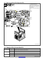
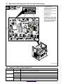
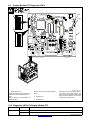
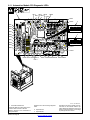
6-4. Removing Cover and Measuring Input Capacitor Voltage 28 . . . . . . . . . . . . . . . . . . . . . . . . . . . . . . . . . . . .
6-5. Weld Process Board PC4 Diagnostic LED’s 29 . . . . . . . . . . . . . . . . . . . . . . . . . . . . . . . . . . . . . . . . . . . . . . .
6-6. Diagnostic LED’s On Process Board PC4 29 . . . . . . . . . . . . . . . . . . . . . . . . . . . . . . . . . . . . . . . . . . . . . . . . .
6-7. Motor Board PC6 Diagnostic LED’s And Dip Switch Settings 30 . . . . . . . . . . . . . . . . . . . . . . . . . . . . . . . . .
6-8. Diagnostic LED’s On Motor Board PC6 30 . . . . . . . . . . . . . . . . . . . . . . . . . . . . . . . . . . . . . . . . . . . . . . . . . . .
6-9. Display Module PC7 Diagnostic LED’s 31 . . . . . . . . . . . . . . . . . . . . . . . . . . . . . . . . . . . . . . . . . . . . . . . . . . . .
6-10. Diagnostic LED’s On Display Module PC7 31 . . . . . . . . . . . . . . . . . . . . . . . . . . . . . . . . . . . . . . . . . . . . . . . .
6-11. Automation Module PC9 Diagnostic LED’s 32 . . . . . . . . . . . . . . . . . . . . . . . . . . . . . . . . . . . . . . . . . . . . . . . .
6-12. Diagnostic LED’s On Automation Module PC9 33 . . . . . . . . . . . . . . . . . . . . . . . . . . . . . . . . . . . . . . . . . . . . .
6-13. Network Status Table 34 . . . . . . . . . . . . . . . . . . . . . . . . . . . . . . . . . . . . . . . . . . . . . . . . . . . . . . . . . . . . . . . . . .
6-14. Robot Reset Mode 35 . . . . . . . . . . . . . . . . . . . . . . . . . . . . . . . . . . . . . . . . . . . . . . . . . . . . . . . . . . . . . . . . . . . .
6-15. Troubleshooting 36 . . . . . . . . . . . . . . . . . . . . . . . . . . . . . . . . . . . . . . . . . . . . . . . . . . . . . . . . . . . . . . . . . . . . . .
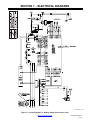
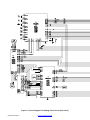
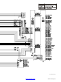
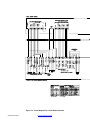
SECTION 7 − ELECTRICAL DIAGRAMS 37 . . . . . . . . . . . . . . . . . . . . . . . . . . . . . . . . . . . . . . . . . . . . . . . . . . . . . . . .
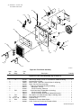
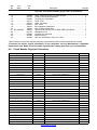
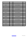
SECTION 8 − PARTS LIST 44 . . . . . . . . . . . . . . . . . . . . . . . . . . . . . . . . . . . . . . . . . . . . . . . . . . . . . . . . . . . . . . . . . . . . .
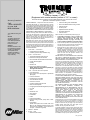
WARRANTY

OM-207 991 Page 1
Return To Table Of Contents
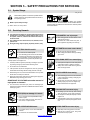
SECTION 1 − SAFETY PRECAUTIONS - READ BEFORE USING
som _8/03
1-1. Symbol Usage
Means Warning! Watch Out! There are possible hazards
with this procedure! The possible hazards are shown in
the adjoining symbols.
Y Marks a special safety message.
. Means “Note”; not safety related.
This group of symbols means Warning! Watch Out! possible
ELECTRIC SHOCK, MOVING PARTS, and HOT PARTS hazards.
Consult symbols and related instructions below for necessary actions
to avoid the hazards.
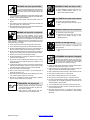
1-2. Arc Welding Hazards
Y The symbols shown below are used throughout this manual to
call attention to and identify possible hazards. When you see
the symbol, watch out, and follow the related instructions to
avoid the hazard. The safety information given below is only
a summary of the more complete safety information found in
the Safety Standards listed in Section 1-5. Read and follow all
Safety Standards.
Y Only qualified persons should install, operate, maintain, and
repair this unit.
Y During operation, keep everybody, especially children, away.
ELECTRIC SHOCK can kill.
Touching live electrical parts can cause fatal shocks
or severe burns. The electrode and work circuit is
electrically live whenever the output is on. The input
power circuit and machine internal circuits are also
live when power is on. In semiautomatic or automatic wire welding, the
wire, wire reel, drive roll housing, and all metal parts touching the
welding wire are electrically live. Incorrectly installed or improperly
grounded equipment is a hazard.
D Do not touch live electrical parts.
D Wear dry, hole-free insulating gloves and body protection.
D Insulate yourself from work and ground using dry insulating mats
or covers big enough to prevent any physical contact with the work
or ground.
D Do not use AC output in damp areas, if movement is confined, or if
there is a danger of falling.
D Use AC output ONLY if required for the welding process.
D If AC output is required, use remote output control if present on
unit.
D Disconnect input power or stop engine before installing or
servicing this equipment. Lockout/tagout input power according to
OSHA 29 CFR 1910.147 (see Safety Standards).
D Properly install and ground this equipment according to its
Owner’s Manual and national, state, and local codes.
D Always verify the supply ground − check and be sure that input
power cord ground wire is properly connected to ground terminal in
disconnect box or that cord plug is connected to a properly
grounded receptacle outlet.
D When making input connections, attach proper grounding conduc-
tor first − double-check connections.
D Frequently inspect input power cord for damage or bare wiring −
replace cord immediately if damaged − bare wiring can kill.
D Turn off all equipment when not in use.
D Do not use worn, damaged, undersized, or poorly spliced cables.
D Do not drape cables over your body.
D If earth grounding of the workpiece is required, ground it directly
with a separate cable.
D Do not touch electrode if you are in contact with the work, ground,
or another electrode from a different machine.
D Use only well-maintained equipment. Repair or replace damaged
parts at once. Maintain unit according to manual.
D Wear a safety harness if working above floor level.
D Keep all panels and covers securely in place.
D Clamp work cable with good metal-to-metal contact to workpiece
or worktable as near the weld as practical.
D Insulate work clamp when not connected to workpiece to prevent
contact with any metal object.
D Do not connect more than one electrode or work cable to any
single weld output terminal.
SIGNIFICANT DC VOLTAGE exists after removal of
input power on inverters.
D Turn Off inverter, disconnect input power, and discharge input
capacitors according to instructions in Maintenance Section
before touching any parts.
Welding produces fumes and gases. Breathing
these fumes and gases can be hazardous to your
health.
FUMES AND GASES can be hazardous.
D Keep your head out of the fumes. Do not breathe the fumes.
D If inside, ventilate the area and/or use exhaust at the arc to remove
welding fumes and gases.
D If ventilation is poor, use an approved air-supplied respirator.
D Read the Material Safety Data Sheets (MSDSs) and the
manufacturer’s instructions for metals, consumables, coatings,
cleaners, and degreasers.
D Work in a confined space only if it is well ventilated, or while
wearing an air-supplied respirator. Always have a trained watch-
person nearby. Welding fumes and gases can displace air and
lower the oxygen level causing injury or death. Be sure the breath-
ing air is safe.
D Do not weld in locations near degreasing, cleaning, or spraying op-
erations. The heat and rays of the arc can react with vapors to form
highly toxic and irritating gases.
D Do not weld on coated metals, such as galvanized, lead, or
cadmium plated steel, unless the coating is removed from the weld
area, the area is well ventilated, and if necessary, while wearing an
air-supplied respirator. The coatings and any metals containing
these elements can give off toxic fumes if welded.

OM-207 991 Page 2
Return To Table Of Contents
Arc rays from the welding process produce intense
visible and invisible (ultraviolet and infrared) rays
that can burn eyes and skin. Sparks fly off from the
weld.
ARC RAYS can burn eyes and skin.
D Wear a welding helmet fitted with a proper shade of filter to protect
your face and eyes when welding or watching (see ANSI Z49.1
and Z87.1 listed in Safety Standards).
D Wear approved safety glasses with side shields under your
helmet.
D Use protective screens or barriers to protect others from flash and
glare; warn others not to watch the arc.
D Wear protective clothing made from durable, flame-resistant mate-
rial (leather and wool) and foot protection.
Welding on closed containers, such as tanks,
drums, or pipes, can cause them to blow up. Sparks
can fly off from the welding arc. The flying sparks, hot
workpiece, and hot equipment can cause fires and
burns. Accidental contact of electrode to metal objects can cause
sparks, explosion, overheating, or fire. Check and be sure the area is
safe before doing any welding.
WELDING can cause fire or explosion.
D Protect yourself and others from flying sparks and hot metal.
D Do not weld where flying sparks can strike flammable material.
D Remove all flammables within 35 ft (10.7 m) of the welding arc. If
this is not possible, tightly cover them with approved covers.
D Be alert that welding sparks and hot materials from welding can
easily go through small cracks and openings to adjacent areas.
D Watch for fire, and keep a fire extinguisher nearby.
D Be aware that welding on a ceiling, floor, bulkhead, or partition can
cause fire on the hidden side.
D Do not weld on closed containers such as tanks, drums, or pipes,
unless they are properly prepared according to AWS F4.1 (see
Safety Standards).
D Connect work cable to the work as close to the welding area as
practical to prevent welding current from traveling long, possibly
unknown paths and causing electric shock and fire hazards.
D Do not use welder to thaw frozen pipes.
D Remove stick electrode from holder or cut off welding wire at
contact tip when not in use.
D Wear oil-free protective garments such as leather gloves, heavy
shirt, cuffless trousers, high shoes, and a cap.
D Remove any combustibles, such as a butane lighter or matches,
from your person before doing any welding.
FLYING METAL can injure eyes.
D Welding, chipping, wire brushing, and grinding
cause sparks and flying metal. As welds cool,
they can throw off slag.
D Wear approved safety glasses with side
shields even under your welding helmet.
BUILDUP OF GAS can injure or kill.
D Shut off shielding gas supply when not in use.
D Always ventilate confined spaces or use
approved air-supplied respirator.
HOT PARTS can cause severe burns.
D Do not touch hot parts bare handed.
D Allow cooling period before working on gun or
torch.
MAGNETIC FIELDS can affect pacemakers.
D Pacemaker wearers keep away.
D Wearers should consult their doctor before
going near arc welding, gouging, or spot
welding operations.
NOISE can damage hearing.
Noise from some processes or equipment can
damage hearing.
D Wear approved ear protection if noise level is
high.
Shielding gas cylinders contain gas under high
pressure. If damaged, a cylinder can explode. Since
gas cylinders are normally part of the welding
process, be sure to treat them carefully.
CYLINDERS can explode if damaged.
D Protect compressed gas cylinders from excessive heat, mechani-
cal shocks, slag, open flames, sparks, and arcs.
D Install cylinders in an upright position by securing to a stationary
support or cylinder rack to prevent falling or tipping.
D Keep cylinders away from any welding or other electrical circuits.
D Never drape a welding torch over a gas cylinder.
D Never allow a welding electrode to touch any cylinder.
D Never weld on a pressurized cylinder − explosion will result.
D Use only correct shielding gas cylinders, regulators, hoses, and fit-
tings designed for the specific application; maintain them and
associated parts in good condition.
D Turn face away from valve outlet when opening cylinder valve.
D Keep protective cap in place over valve except when cylinder is in
use or connected for use.
D Read and follow instructions on compressed gas cylinders,
associated equipment, and CGA publication P-1 listed in Safety
Standards.

OM-207 991 Page 3
Return To Table Of Contents
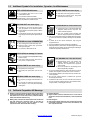
1-3. Additional Symbols For Installation, Operation, And Maintenance
FIRE OR EXPLOSION hazard.
D Do not install or place unit on, over, or near
combustible surfaces.
D Do not install unit near flammables.
D Do not overload building wiring − be sure power supply system is
properly sized, rated, and protected to handle this unit.
FALLING UNIT can cause injury.
D Use lifting eye to lift unit only, NOT running
gear, gas cylinders, or any other accessories.
D Use equipment of adequate capacity to lift and
support unit.
D If using lift forks to move unit, be sure forks are
long enough to extend beyond opposite side of
unit.
OVERUSE can cause OVERHEATING
D Allow cooling period; follow rated duty cycle.
D Reduce current or reduce duty cycle before
starting to weld again.
D Do not block or filter airflow to unit.
STATIC (ESD) can damage PC boards.
D Put on grounded wrist strap BEFORE handling
boards or parts.
D Use proper static-proof bags and boxes to
store, move, or ship PC boards.
MOVING PARTS can cause injury.
D Keep away from moving parts.
D Keep away from pinch points such as drive
rolls.
WELDING WIRE can cause injury.
D Do not press gun trigger until instructed to do
so.
D Do not point gun toward any part of the body,
other people, or any metal when threading
welding wire.
MOVING PARTS can cause injury.
D Keep away from moving parts such as fans.
D Keep all doors, panels, covers, and guards
closed and securely in place.
H.F. RADIATION can cause interference.
D High-frequency (H.F.) can interfere with radio
navigation, safety services, computers, and
communications equipment.
D Have only qualified persons familiar with
electronic equipment perform this installation.
D The user is responsible for having a qualified electrician prompt-
ly correct any interference problem resulting from the installa-
tion.
D If notified by the FCC about interference, stop using the
equipment at once.
D Have the installation regularly checked and maintained.
D Keep high-frequency source doors and panels tightly shut, keep
spark gaps at correct setting, and use grounding and shielding to
minimize the possibility of interference.
ARC WELDING can cause interference.
D Electromagnetic energy can interfere with
sensitive electronic equipment such as
computers and computer-driven equipment
such as robots.
D Be sure all equipment in the welding area is
electromagnetically compatible.
D To reduce possible interference, keep weld cables as short as
possible, close together, and down low, such as on the floor.
D Locate welding operation 100 meters from any sensitive elec-
tronic equipment.
D Be sure this welding machine is installed and grounded
according to this manual.
D If interference still occurs, the user must take extra measures
such as moving the welding machine, using shielded cables,
using line filters, or shielding the work area.
1-4. California Proposition 65 Warnings
Y Welding or cutting equipment produces fumes or gases which
contain chemicals known to the State of California to cause
birth defects and, in some cases, cancer. (California Health &
Safety Code Section 25249.5 et seq.)
Y Battery posts, terminals and related accessories contain lead
and lead compounds, chemicals known to the State of
California to cause cancer and birth defects or other
reproductive harm. Wash hands after handling.
For Gasoline Engines:
Y Engine exhaust contains chemicals known to the State of
California to cause cancer, birth defects, or other reproductive
harm.
For Diesel Engines:
Y Diesel engine exhaust and some of its constituents are known
to the State of California to cause cancer, birth defects, and
other reproductive harm.

OM-207 991 Page 4
Return To Table Of Contents
1-5. Principal Safety Standards
Safety in Welding, Cutting, and Allied Processes, ANSI Standard Z49.1,
from American Welding Society, 550 N.W. LeJeune Rd, Miami FL 33126
(phone: 305-443-9353, website: www.aws.org).
Recommended Safe Practices for the Preparation for Welding and Cut-
ting of Containers and Piping, American Welding Society Standard
AWS F4.1, from American Welding Society, 550 N.W. LeJeune Rd, Mi-
ami, FL 33126 (phone: 305-443-9353, website: www.aws.org).
National Electrical Code, NFPA Standard 70, from National Fire Protec-
tion Association, P.O. Box 9101, 1 Battery March Park, Quincy, MA
02269−9101 (phone: 617−770−3000, website: www.nfpa.org and www.
sparky.org).
Safe Handling of Compressed Gases in Cylinders, CGA Pamphlet P-1,
from Compressed Gas Association, 1735 Jefferson Davis Highway,
Suite 1004, Arlington, VA 22202−4102 (phone: 703−412−0900, web-
site: www.cganet.com).
Code for Safety in Welding and Cutting, CSA Standard W117.2, from
Canadian Standards Association, Standards Sales, 178 Rexdale
Boulevard, Rexdale, Ontario, Canada M9W 1R3 (phone:
800−463−6727 or in Toronto 416−747−4044, website: www.csa−in-
ternational.org).
Practice For Occupational And Educational Eye And Face Protection,
ANSI Standard Z87.1, from American National Standards Institute, 11
West 42nd Street, New York, NY 10036−8002 (phone: 212−642−4900,
website: www.ansi.org).
Standard for Fire Prevention During Welding, Cutting, and Other Hot
Work, NFPA Standard 51B, from National Fire Protection Association,
P.O. Box 9101, 1 Battery March Park, Quincy, MA 02269−9101 (phone:
617−770−3000, website: www.nfpa.org and www. sparky.org).
OSHA, Occupational Safety and Health Standards for General Indus-
try, Title 29, Code of Federal Regulations (CFR), Part 1910, Subpart Q,
and Part 1926, Subpart J, from U.S. Government Printing Office, Super-
intendent of Documents, P.O. Box 371954, Pittsburgh, PA 15250 (there
are 10 Regional Offices−−phone for Region 5, Chicago, is
312−353−2220, website: www.osha.gov).
1-6. EMF Information
Considerations About Welding And The Effects Of Low Frequency
Electric And Magnetic Fields
Welding current, as it flows through welding cables, will cause electro-
magnetic fields. There has been and still is some concern about such
fields. However, after examining more than 500 studies spanning 17
years of research, a special blue ribbon committee of the National
Research Council concluded that: “The body of evidence, in the
committee’s judgment, has not demonstrated that exposure to power-
frequency electric and magnetic fields is a human-health hazard.”
However, studies are still going forth and evidence continues to be
examined. Until the final conclusions of the research are reached, you
may wish to minimize your exposure to electromagnetic fields when
welding or cutting.
To reduce magnetic fields in the workplace, use the following
procedures:
1. Keep cables close together by twisting or taping them.
2. Arrange cables to one side and away from the operator.
3. Do not coil or drape cables around your body.
4. Keep welding power source and cables as far away from opera-
tor as practical.
5. Connect work clamp to workpiece as close to the weld as possi-
ble.
About Pacemakers:
Pacemaker wearers consult your doctor first. If cleared by your doctor,
then following the above procedures is recommended.
Page is loading ...
Page is loading ...
Page is loading ...

OM-207 991 Page 8
Revenez à la table des matières
2-4. Principales normes de sécurité
Safety in Welding, Cutting, and Allied Processes, norme ANSI Z49.1,
de l’American Welding Society, 550 N.W. LeJeune Rd, Miami FL 33126
(téléphone : (305) 443−9353, site Web : www.aws.org).
Recommended Safe Practices for the Preparation for Welding and Cut-
ting of Containers and Piping, norme American Welding Society AWS
F4.1, de l’American Welding Society, 550 N.W. LeJeune Rd, Miami, FL
33126 (téléphone : (305) 443−9353, site Web : www.aws.org).
National Electrical Code, norme NFPA 70, de la National Fire Protection
Association, P.O. Box 9101, 1 Battery March Park, Quincy, MA
02269−9101 (téléphone : (617) 770−3000, sites Web : www.nfpa.org et
www.sparky.org).
Safe Handling of Compressed Gases in Cylinders, brochure CGA P−1,
de la Compressed Gas Association, 1735 Jefferson Davis Highway,
Suite 1004, Arlington, VA 22202−4102 (téléphone : (703) 412−0900,
site Web : www.cganet.com).
Code for Safety in Welding and Cutting, norme CSA W117.2, de la Ca-
nadian Standards Association, Standards Sales, 178 boulevard
Rexdale, Rexdale (Ontario) Canada M9W 1R3 (téléphone : (800)
463−6727 ou à Toronto : (416) 747−4044, site Web : www.csa−interna-
tional.org).
Practice For Occupational And Educational Eye And Face Protection,
norme ANSI Z87.1, de l’American National Standards Institute, 11 West
42nd Street, New York, NY 10036−8002 (téléphone : (212) 642−4900,
site Web : www.ansi.org).
Standard for Fire Prevention During Welding, Cutting, and Other Hot
Work, norme NFPA 51B, de la National Fire Protection Association,
P.O. Box 9101, 1 Battery March Park, Quincy, MA 02269−9101 (télé-
phone : (617) 770−3000, site Web : www.nfpa.org et www.sparky.org).
OSHA, Occupational Safety and Health Standards for General Indus-
try, Title 29, Code of Federal Regulations (CFR), Part 1910, Subpart Q,
and Part 1926, Subpart J, de l’U.S. Government Printing Office, Super-
intendent of Documents, P.O. Box 371954, Pittsburgh, PA 15250 (il y a
10 bureaux régionaux − Téléphone pour la Région 5, Chicago : (312)
353−2220, site Web : www.osha.gov).
2-5. Information sur les champs électromagnétiques
Données sur le soudage électrique et les effets des champs magnéti-
ques basse fréquence sur l’organisme
En parcourant les câbles de soudage, le courant crée des champs élec-
tromagnétiques. Les effets potentiels de tels champs restent
préoccupants. Cependant, après avoir examiné plus de 500 études qui
ont été faites pendant une période de recherche de 17 ans, un comité
de spécialistes du National Research Council a conclu : « L’accumula-
tion de preuves n’a pas démontré que l’exposition aux champs
magnétiques et aux champs électriques à haute fréquence constitue un
risque pour la santé humaine ». Toutefois, les études et l’examen des
preuves se poursuivent. En attendant les conclusions finales de la re-
cherche, il serait souhaitable de réduire l’exposition aux champs
électromagnétiques pendant le soudage ou le coupage.
Afin de réduire les champs électromagnétiques en milieu de travail, res-
pecter les consignes suivantes :
1. Garder les câbles ensemble en les torsadant ou en les fixant avec du
ruban adhésif.
2. Mettre tous les câbles du côté opposé à l’opérateur.
3. Ne pas s’enrouler les câbles autour du corps.
4. Garder le poste de soudage et les câbles le plus loin possible de soi.
5. Placer la pince de masse le plus près possible de la zone de soudage.
Consignes relatives aux stimulateurs cardiaques :
Les personnes qui portent un stimulateur cardiaque doivent avant tout
consulter leur médecin. Si ce dernier les déclare aptes, il leur est recom-
mandé de respecter les consignes ci-dessus.

OM-207 991 Page 9
Return To Table Of Contents
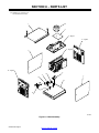
SECTION 3 − INSTALLATION
Appearance of actual unit may vary from unit shown in manual.
NOTE
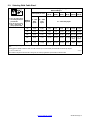
3-1. Specifications
Input
Power
Rated
Weldin
g
Voltage
Range
Amperage
Ran
g
e In
Wire Feed
S
p
eed
Wire
Diameter
Max
Open
Circuit
Amperes Input At Rated Load Output 60 Hz,
Single-Phase/Three-Phase
Input
kVA
Input
KW
Power
Welding
Output
Range
Range In
CC Mode
Speed
Range**
Diameter
Range
Circuit
Voltage
DC
208 V 230 V 400V 460 V 575 V
kVA KW
Single
Phase
175 A @
27 V DC,
100%
Duty
Cycle
10 44
5 400 A
Standard:
50-1400
ipm
.030-.062 in
(0 8 1 6
80
30.0
(0-1A*)
27.2
(0-1A*)
15.0
(0-1A*)
12.8
(0-1A*)
10.2
(0-1A*)
6.3
(0.2*)
5.8
(0.04*)
Three
Phase
225 A @
29 V DC,
100%
Duty
Cycle
10-44 5-400 A
ipm
(1.3-35.6
mpm)
(0.8-1.6
mm)
80
23.0 20.8 11.8 10.2 8.1 8.3
(0.2*)
7.9
(0.04*)
*While idling; Input amperage fluctuates while idling and is always less than one Ampere. Use one Ampere for power efficiency calculations.
**Wire feed speed ranges are for GMAW welding. While pulse welding, wire feed speed ranges may be more limited.
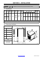
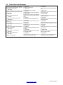
3-2. Dimensions And Weight
Hole Layout Dimensions
A
E
A 17-3/32 in (434 mm)
A
B 17-3/8 in (441 mm)
22-1/2 in
(572 mm)
C 19-3/32 in (485 mm)
23 in
D 16-3/32 in (409 mm)
B
C
23 i
n
(584 mm)
E 1/2 in (13 mm)
Weight
17-3/32 in
(434 mm)
116 lb (53 kg) Net
128 lb (58 kg) Ship
D
803 675-A
()

OM-207 991 Page 10
Return To Table Of Contents
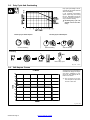
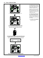
3-3. Duty Cycle And Overheating
Duty Cycle is percentage of 10 min-
utes that unit can weld at rated load
without overheating.
If unit overheats, thermostat(s)
opens, output stops, and cooling
fan runs. Wait fifteen minutes for
unit to cool. Reduce amperage or
duty cycle before welding.
Y Exceeding duty cycle can
damage unit and void war-
ranty.
Overheating
0
15
A/V
OR
Reduce Duty Cycle
Minutes
duty1 4/95 − 178 651
Continuous Welding
100% Duty Cycle At 225 Amperes 60% Duty Cycle At 300 Amperes
6 Minutes Welding 4 Minutes Resting
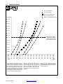
3-4. Volt-Ampere Curves
va_curve1 4/95
Volt-ampere curves show minimum
and maximum voltage and amper-
age output capabilities of unit.
Curves of other settings fall be-
tween curves shown.
. This volt-ampere curve repre-
sents the dynamic output of the
unit with a static load.
CV MODE
0
10
20
30
40
50
60
70
80
0 100 200 300 400 500 60 0
AMPERAGE
VOLTAGE

OM-207 991 Page 11
Return To Table Of Contents
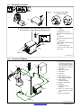
3-5. Selecting A Location
loc_2 3/96 -803 675-A
Y Do not stack units. Beware of
tipping.
1 Lifting Forks
Use lifting forks to move unit.
Extend forks beyond opposite side
of unit.
2 Hand Cart
Use cart or similar device to move
unit.
3 Rating Label
Use rating label to determine input
power needs.
4 Line Disconnect Device
Locate unit near correct input
power supply.
Movement
2
Location
4
18 in
(460 mm)
18 in
(460 mm)
3
Y Do not move or operate
unit where it could tip.
Tipping
1
OR
Y Special installation may be required where gasoline or volatile
liquids are present − see NEC Article 511 or CEC Section 20.
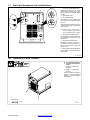
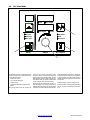
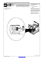
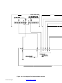
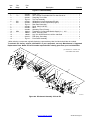
803 675-A / Ref. 801 915-A
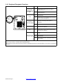
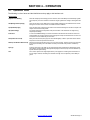
. The proper interface kit must
be installed in the welding pow-
er source/interface unit to allow
it to be connected to the robot.
1 Robot (Will Vary According To
Application)
2 Motor/Drive Assembly
3 Gas Cylinder
4 Gas Hose
5 Robot Control
6 Robot Input/Output Cable
7 Gas And Motor Control Cable
8 Welding Power
Source/Interface Unit
9 Negative (−) Weld Cable
10 Workpiece
11 Voltage Sensing Lead
(Optional)
. Positive (+) voltage sensing
lead is contained in the motor
cable.
12 Positive (+) Weld Cable
1
2 3
4
5
7
6
8
9
10
11
12
3-6. Connection Diagram

OM-207 991 Page 12
Return To Table Of Contents
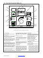
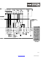
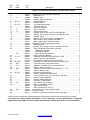
Ref. 803 676-A
1 115 V 10 A AC Receptacle RC2
Receptacle supplies 60 Hz single-
phase power. Maximum output from
RC2 is limited by circuit breaker CB2 to
10 amps.
2 Circuit Breaker CB1
3 Circuit Breaker CB2
CB1 protects 115 volt receptacle RC2
from overload. If CB1 opens, RC2 does
not work.
CB2 protects the wirefeed motor from
overload. If CB2 opens, the wirefeeder
does not work.
. Press button to reset breaker. If
breaker continue to open, contact a
Factory Authorized Service Agent.
4 Wirefeed/Gas Receptacle RC8
Use receptacle to connect gas and mo-
tor control cable to power source (see
Section 3-6).
5 Peripheral Receptacle RC25
Receptacle provides connection to
touch sensor, water flow switch, jog +/−,
and n/o relay contacts circuitry (see
Section 3-10).
6 Robot Interface Receptacle RC72
Use receptacle to connect robot input/
output cable.
2
3
3-7. Rear Panel Receptacles And Circuit Breakers
1
6
4
5
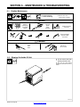
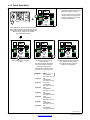
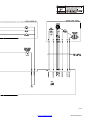
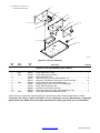
3-8. Connecting To Weld Terminals
Y Turn off power before con-
necting to weld output ter-
minals.
1 Positive (+) Weld Output
Terminal
2 Negative (−) Weld Output
Terminal
Connect positive weld cable to
Positive (+) weld terminal and
negative (−) cable to Negative
weld terminal.
Tools Needed:
803 675-A
1
2
3/4 in

OM-207 991 Page 13
Return To Table Of Contents
3-9. Selecting Weld Cable Sizes*
Weld Cable Size** and Total Cable (Copper) Length in Weld Circuit
Not Exceeding***
100 ft (30 m) or Less
150 ft
(45 m)
200 ft
(60 m)
250 ft
(70 m)
300 ft
(90 m)
350 ft
(105 m)
400 ft
(120 m)
Y Turn off power before
connecting to weld out-
put terminals.
Y Do not use worn, dam-
aged, undersized, or
poorly spliced cables.
Welding
Amperes
10 − 60%
Duty
Cycle
60 − 100%
Duty
Cycle
10 − 100% Duty Cycle
100 4 (20) 4 (20) 4 (20) 3 (30) 2 (35) 1 (50) 1/0 (60) 1/0 (60)
150 3 (30) 3 (30) 2 (35) 1 (50) 1/0 (60) 2/0 (70) 3/0 (95) 3/0 (95)
200 3 (30) 2 (35) 1 (50) 1/0 (60) 2/0 (70) 3/0 (95) 4/0 (120) 4/0 (120)
250 2 (35) 1 (50) 1/0 (60) 2/0 (70) 3/0 (95) 4/0 (120)
2 ea. 2/0
(2x70)
2 ea. 2/0
(2x70)
300 1 (50) 1/0 (60) 2/0 (70) 3/0 (95) 4/0 (120)
2 ea. 2/0
(2x70)
2 ea. 3/0
(2x95)
2 ea. 3/0
(2x95)
* This chart is a general guideline and may not suit all applications. If cable overheating occurs (normally you can smell it), use next size larger
cable.
**Weld cable size (AWG) is based on either a 4 volts or less drop or a current density of at least 300 circular mils per ampere.
( ) = mm
2
for metric use S-0007-E
***For distances longer than those shown in this guide, call a factory applications representative at 920-735-4505.

OM-207 991 Page 14
Return To Table Of Contents
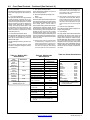
3-10. Peripheral Receptacle Functions
Function Socket Socket Information
Programmable
Output Relay Con
A Contact closure to B dependent upon state of
programmed output.
Output Relay Con-
tacts
B Contact closure to A dependent upon state of
programmed output.
C* Circuit common.
K
M
J
L
H
E
F
Purge
D Contact closure to C completes 24 volts dc solenoid
circuit to purge shielding gas line.
A
B
C
L
D
E
Coolant Flow
Switch In
p
ut Si
g
nal
E Contact closure to F indicates coolant flow switch is
closed and recirculating coolant system is
operational.
Switch Input Signal
F* Circuit common.
Jog + H** Contact closure to circuit common advances welding
wire at wire drive assembly.
Ref. 803 675-A
Jog − J** Contact closure to circuit common retracts welding
wire at wire drive assembly.
K Contact closure to L energizes Touch Sensor
circuitry.
Touch Sensor ON
And Output Signal
L* Circuit common.
And Output Signal
M Part touched +24 volts dc output signal referenced to
circuit common.
*Circuit common is same electrical reference point.
**Speed of Jog + and Jog − is at setup value for Jog IPM parameter.
Note: A customer supplied matching amphenol plug (Part No. MS3106A20-33P and strain relief clamp AN3057-12) is required to use peripheral
receptacle.

OM-207 991 Page 15
Return To Table Of Contents
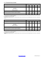
3-11. Electrical Service Guide
Single Phase 50/60 Hz
Input Voltage 208 230 400 460 575
Input Amperes At Rated Output 30 27 15 13 10
Max Recommended Standard Fuse Rating In Amperes
1
Time-Delay
2
35 30 15 15 10
Normal Operating 3 45 40 25 20 15
Min Input Conductor Size In AWG 8 10 12 14 14
Max Recommended Input Conductor Length In Feet (Meters)
138
(42)
111
(34)
203
(62)
174
(53)
272
(83)
Min Grounding Conductor Size In AWG 10 10 12 14 14
Reference: 1999 National Electrical Code (NEC)
1 Consult factory for circuit breaker applications.
2 “Time-Delay” fuses are UL class “RK5” .
3 “Normal Operating” (general purpose - no intentional delay) fuses are UL class “K5” (up to and including 60 amp), and UL class “H” ( 65 amp and
above).
Three Phase 50/60 Hz
Input Voltage 208 230 400 460 575
Input Amperes At Rated Output 23 21 12 10 8
Max Recommended Standard Fuse Rating In Amperes
1
Time-Delay
2
25 25 15 10 10
Normal Operating 3 35 30 15 15 10
Min Input Conductor Size In AWG 10 10 14 14 14
Max Recommended Input Conductor Length In Feet (Meters)
134
(41)
164
(50)
194
(59)
256
(78)
400
(122)
Min Grounding Conductor Size In AWG 10 10 14 14 14
Reference: 1999 National Electrical Code (NEC)
1 Consult factory for circuit breaker applications.
2 “Time-Delay” fuses are UL class “RK5” .
3 “Normal Operating” (general purpose - no intentional delay) fuses are UL class “K5” (up to and including 60 amp), and UL class “H” ( 65 amp and
above).

OM-207 991 Page 16
Return To Table Of Contents
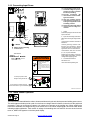
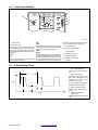
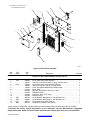
3-12. Connecting Input Power
803 676-A / 218 005-A
Y Turn Off welding power source,
and check voltage on input ca-
pacitors according to Section
6-4 before proceeding.
Y Incorrect connections will
cause electric shock and dam-
age to the machine.
Y Have only qualified persons
perform these connections ac-
cording to all applicable codes
and safety practices.
Y Disconnect input power before
opening door for voltage con-
nections.
1 Clamp
Install clamp of proper size for unit and
input conductors.
2 Input And Grounding Conductors
Select size and length using Section
3-11.
Connect input conductors as shown in
illustration.
Connect grounding conductor first,
then line input conductors. Always
connect green wire to supply ground-
ing terminal, never to a line terminal.
Connect black, white, and red wires
(L1, L2, L3) to line terminals.
Double-check grounding conductor,
inside voltage connections, and input
voltage before applying power.
3 Line Disconnect Device
See Section 3-11.
Close door before operating unit.
Tools Needed:
5/16 in
= GND/PE
Y Always connect grounding
conductor first.
L1
3
L2
L3
2
Route ground conductor through
current transducer to ground terminal.
Route input power cable
through tubing inside unit.
1
Three-Phase Input Connection
Read Owner’s Manual.
ELECTRIC SHOCK can kill;
SIGNIFICANT DC VOLTAGE
exists after removal of
input power.
S Always wait 5 minutes after power
Is turned off before working on unit.
S Check input capacitor voltage, and
be sure it is near 0 before touching
any parts.
WARNING
3-13. Touch Sensor Operation
The touch sensor feature allows the robot to locate a weldment using the wire feed system and welding power source.
The weld output terminals provide a path for touch sensor voltage when this feature is turned on at the peripheral
receptacle. Turning on touch sensor causes a dc voltage to be present on the welding wire. When welding wire
touches the weldment, the voltage sensing circuit closes, and a +24 volts dc output signal is sent to the robot control
indicating weldment detection. Touch sensor dc voltage on the welding wire is 80 volts DC. As soon as touch sensor
turns on, WIRE LIVE appears on the front panel display.

OM-207 991 Page 17
Return To Table Of Contents
SECTION 4 − OPERATION
4-1. Operational Terms
The following is a list of terms and their definitions as they apply to this interface unit:
General Terms:
Adaptive Pulse Welding When the “adaptive pulse” welding process is selected, the unit will attempt to automatically regulate
pulse frequency in order to maintain a constant arc length, regardless of change in welding wire stick-
out.
Abk (Background Amperage) Abk is the low weld current. Background current preheats welding wire and maintains the arc. When
background current is too low, the arc is unstable and hard to maintain.
Apk (Peak Amperage) Apk is the high pulse of welding current. Peak current melts the welding wire and forms a droplet. The
droplet is forced into the weld puddle.
Vpk (Peak Voltage) Arc voltage during peak current phase of the pulse waveform. This determines arc length during
adaptive pulse welding.
Inductance In short circuit GMAW welding, an increase in inductance will decrease the number of short circuit
metal transfers per second (provided no other changes are made) and increase the arc-on time. The
increased arc-on time makes the pool more fluid.
PPS (Pulses Per Second) PPS, pulse rate, and frequency (Hz) are used interchangeably. A PPS or pulse rate of 60 Hz means
60 pulses of current are produced each second.
PWms (Pulse Width in Milliseconds) PWms is the time spent at peak current (1.2 ms is .0012 seconds). This time must be long enough to
form a droplet of welding wire. The stiffness or fluidity of the molten weld puddle is controlled by
PWms.
Synergic Synergic refers to the unit’s ability to use preprogrammed pulse parameters to determine the actual
pulse settings of Peak Amperage, Background Amperage, Pulse Frequency and Pulse Width at any
specific wire feed speed setting.
Trim Term used to represent arc length adjustments in pulse programs. Increasing trim increases the ac-
tual arc length. Likewise, decreasing trim shortens arc length. Trim is replaced by volts in MIG pro-
grams.

OM-207 991 Page 18
Return To Table Of Contents
4-2. Front Panel Controls (See Section 4-3)
Program
Process
Wire Type
Gas Type
Adjust
Volts Arc Length
Wire Speed Amps
Setup Arc Control
Wirefeed
Gas
Contactor
1
3
5
7
2
9
10
11
1415
. When an LED is lit, it means the related function is active.
4
12
13
1 Program Display
Displays the number of the active program.
2 Adjust Control
Use the Adjust control to change program
number, Setup and Arc Control parameters.
3 Program Push Button LED
The LED lights when the Program Push But-
ton is active and the Adjust control can be
used to change the program. LED goes out
when Program push button is inactive.
4 Program Push Button
Press push button (LED lights) and turn Adjust
control to select active program. Press button
again to deactivate button (LED goes out).
The letter C is displayed with the program
number if the program has been changed from
the factory settings using the optional control
pendant (see Pendant Owner’s Manual).
. The program cannot be changed through
the front panel while welding.
Press and hold button to see program name
assigned by user using optional control pen-
dant. Program name is shown in upper and
lower displays (items 13 and 15). Display
reads ”AAAA” if no name is assigned to pro-
gram.
5 Setup Mode Indicators
The lit LED indicates which setup mode is ac-
tive. Setup mode parameters are shown in
Display Windows (see Items 13 and 15).
Process LED
When this LED is lit, turn the Adjust control to
select the desired weld process. Choices in-
clude pulse welding (displayed as PULS) and
MIG welding (MIG).
Wire Type LED
When this LED is lit, turn the Adjust control to
select the desired wire type and size. Wire
type and size choices vary according to the
selected weld process. Choices may include
steel (displayed as STL), stainless steel (SS),
metal core (MCOR), 4043 aluminum (AL4X),
and 5356 aluminum (AL5X). See Table 4-1 for
all wire abbreviations.
Gas Type LED
When this LED is lit, turn the Adjust control to
select the desired weld gas. Gas type choices
vary according to the selected weld process.
Some choices may include:
100% argon (displayed as ARGN GAS)
90% argon, 10% CO
2
(C10 GAS)
98% argon, 2% CO
2
(C2 GAS)
98% argon, 2% O2 (OX
2
GAS).
See Table 4-2 for all gas abbreviations.
6 Setup Push Button LED
The LED lights to indicate one of the setup
modes is active.
7 Setup Push Button
Press button to select Process, Wire Type, or
Gas Type parameters.
. In order for selections to be retained in
memory, the Setup push button must be
pressed four times before any other push
button is pressed: once to select Process,
again to select Wire Type, again to select
Gas Type, and a fourth time to store
selections in memory. The displays will
temporarily show “PROG LOAD” to indi-
cate the data is being stored in memory.
6
8
198 993

OM-207 991 Page 19
Return To Table Of Contents
4-3. Front Panel Controls - Continued (See Section 4-2)
8 Arc Control LED
The LED lights to indicate the Arc Control but-
ton is active. Light goes out when button is in-
active.
9 Arc Control Push Button
This push button allows fine tuning inductance
for MIG programs, and Sharp Arc for pro-
grams other than MIG. When the push button
is pressed, the upper display (item 15) shows
INDU for inductance, or ARC for Sharp Arc to
indicate which parameter is selected for
change. The range of possible values is 0-99
for inductance, and 0-20 for sharp arc. Turn
the Adjust control to change the parameter
value. Press button to deactivate arc control
mode (LED goes out).
10 Wire Feed/Gas/Contactor LEDs
The Wirefeed LED lights when the wire feeder
is energized. For example, when the front
panel Jog or Retract button is pressed, the
Wirefeed LED lights.
The Gas LED lights when the gas valve is en-
ergized.
The Contactor LED lights when the output
contactor is energized, making the weld out-
put terminals live.
11 Wire Speed And Amps LED’s
The lit LED indicates whether wire speed or
amps are being displayed.
12 Wire Feed Speed/Amps Display Push
Button
13 Lower Display
Press Wire Feed Speed/Amps Display button
to show weld amperage or wire feed speed in
lower display (the applicable LED under the
lower display lights to indicate which is
shown). When welding, actual value is shown.
If amperage was selected for display, the unit
will show actual welding amperage prior to
and while welding unless the optional control
pendant was used to set the unit in Display
Command Values mode. Only wire speed
command will be displayed while welding if the
unit is set in Display Command Values mode,
even if the Wire Feed Speed/Amps Display
button is pressed.
. Displays show actual or command values
as determined by configuration menu in
optional control pendant. Command val-
ues are displayed prior to welding and ac-
tual values are displayed while welding
unless the optional control pendant was
used to set the unit in the ”Display Com-
mand Values” mode. In the Display Com-
mand Values mode, command values are
displayed while welding.
. If the optional control pendant is used to
change the wire feed units (IPM, MPM) or
display welding information (command or
actual),save the changes and then turn
the power to the unit off and then on again
for the changes to be carried out by the
unit.
14 Volts And Arc Length LED’s
The lit LED indicates whether voltage or arc
length is being displayed.
15 Upper Display
The upper display shows different information
depending on the active function of the unit
and the weld process being used. When the
display shows voltage (for a MIG process),
the Volts LED lights. When it shows arc length
(for a pulsed weld process), the Arc Length
LED lights. However, during any weld process
(MIG and pulse), the unit will display actual arc
voltage unless the optional control pendant
has set the unit in the ”Display Command Val-
ues” mode.
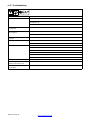
Wire
Description
Abbreviation
Steel
(ER70 S-3)
ER70 S-6)
STL
Stainless Steel
(ER309L)
SS
Cored
Tubular Wire
(Metalox 76)
MCOR
Aluminum
(ER5356)
Aluminum
(ER4043)
AL5X
AL4X
* Not all wire types may be
available with your unit.
Manufacturer Abbreviation
ABB ABB. . . . . . . . . . . . . . . . . . .
Fanuc FANU. . . . . . . . . . . . . . . .
Daihen DAHN. . . . . . . . . . . . . . .
Kawasaki KAWA. . . . . . . . . . . . .
Motoman MOTO. . . . . . . . . . . . . .
Kuka KUKA. . . . . . . . . . . . . . . . .
Comau COMU. . . . . . . . . . . . . . .
Hitachi HCHI. . . . . . . . . . . . . . . . .
Nachi NCHI. . . . . . . . . . . . . . . . . .
Panasonic PANA. . . . . . . . . . . . .
Reis REIS. . . . . . . . . . . . . . . . . . .
Robot Adapter DTEC. . . . . . . . . .
Detect Disabled OFF. . . . . . . . .
Robot Abbreviations*
* An abbreviation of NONE means
no robot is detected.
Full Gas Name Displayed Gas Name
(4 Digits Only)
100% CO2 CO2
100% Argon ARGN
75% Argon, 25% CO2 C25
80% Argon, 20% CO2 C20
85% Argon, 15% CO2 C15
90% Argon, 10% CO2 C10
92% Argon, 8% CO2 C8
95% Argon, 5% CO2 C5
98% Argon, 2% CO2 C2
90% Argon, 7-1/2%
CO2, 2 1/2% O2 ACOX
95% Argon, 5% O2 OX5
98% Argon, 2% O2 OX2
90% Helium, 7-1/2% Ar,
2-1/2% CO2 HE90
75% Helium, 25% Ar HE75
55% Helium, 42-1/2% Ar,
2-1/2% CO2 HE55
50% Helium, 50% Ar HE50
25% Helium, 75% Ar HE25
* Not all wire types may be available with
your unit.
Table 4-1. Welding Wire
Abbreviations*
Table 4-2. Welding Gas
Abbreviations*
Table 4-3. Robot Abbreviations*
Page is loading ...
Page is loading ...
Page is loading ...
Page is loading ...
Page is loading ...
Page is loading ...
Page is loading ...
Page is loading ...
Page is loading ...
Page is loading ...
Page is loading ...
Page is loading ...
Page is loading ...
Page is loading ...
Page is loading ...
Page is loading ...
Page is loading ...
Page is loading ...
Page is loading ...
Page is loading ...
Page is loading ...
Page is loading ...
Page is loading ...
Page is loading ...
Page is loading ...
Page is loading ...
Page is loading ...
Page is loading ...
Page is loading ...
Page is loading ...
Page is loading ...
Page is loading ...
Page is loading ...
Page is loading ...
Page is loading ...
Page is loading ...
Page is loading ...
-
 1
1
-
 2
2
-
 3
3
-
 4
4
-
 5
5
-
 6
6
-
 7
7
-
 8
8
-
 9
9
-
 10
10
-
 11
11
-
 12
12
-
 13
13
-
 14
14
-
 15
15
-
 16
16
-
 17
17
-
 18
18
-
 19
19
-
 20
20
-
 21
21
-
 22
22
-
 23
23
-
 24
24
-
 25
25
-
 26
26
-
 27
27
-
 28
28
-
 29
29
-
 30
30
-
 31
31
-
 32
32
-
 33
33
-
 34
34
-
 35
35
-
 36
36
-
 37
37
-
 38
38
-
 39
39
-
 40
40
-
 41
41
-
 42
42
-
 43
43
-
 44
44
-
 45
45
-
 46
46
-
 47
47
-
 48
48
-
 49
49
-
 50
50
-
 51
51
-
 52
52
-
 53
53
-
 54
54
-
 55
55
-
 56
56
-
 57
57
-
 58
58
-
 59
59
-
 60
60


Miller AUTO-AXCESS 300 Owner's manual
- Category
- Welding System
- Type
- Owner's manual
- This manual is also suitable for
Ask a question and I''ll find the answer in the document
Finding information in a document is now easier with AI
Related papers
-
Miller AUTO-AXCESS 300 Owner's manual
-
Miller LC724363 Owner's manual
-
-
Miller LF203270 Owner's manual
-
-
-
-
-
-
Miller LE164395 Owner's manual
Other documents
-
Miller Electric Axcess 300 User manual
-
HobartWelders CHAMPION 10,000 KOHLER Owner's manual
-
Lincoln Electric IM839 User manual
-
Kawasaki E Series Operating instructions
-
-
ESAB Teaching Mode Operation for Digipulse Wire Feeder Troubleshooting instruction
-
-
-
Lincoln Electric AutoDrive SA Operating instructions
-
 Xantrex RC2 Remote Control Owner's manual
