Page is loading ...

00809-0100-4754
English
Rev. BB
Model 333 HART
®
Tri-Loop
™
HART-to-Analog
Signal Converter


Model 333 HART
®
Tri-Loop
™
HART-to-Analog
Signal Converter
Product Manual
HART Tri-Loop Software Revision 1
HART Tri-Loop Configurator Software Revision 1.02
Rosemount and the Rosemount logotype are registered trademarks of Rosemount Inc.
Tri-Loop, Multivariable, MV, and Hot Backup are trademarks of Rosemount Inc.
HART is a registered trademark of the HART Communication Foundation.
Microsoft and Windows are registered trademarks of Microsoft Corp.
Cover Photo: 3095-005AB
Read this manual before working with the product. For personal and system
safety, and for optimum product performance, make sure you thoroughly
understand the contents before installing, using, or maintaining this product.
Within the United States, Rosemount Inc. has two toll-free assistance numbers.
Customer Central: 1-800-999-9307 (
7:00 a.m. to 7:00 p.m. CST)
Technical support, quoting, and order-related questions.
North American 1-800-654-7768 (
24 hours a day – Includes Canada)
Response Center: Equipment service needs.
For equipment service or support needs outside the United States, contact your
local Rosemount representative.
The products described in this document are NOT designed for nuclear-
qualified applications.
Using non-nuclear qualified products in applications that require nuclear-
qualified hardware or products may cause inaccurate readings.
For information on Rosemount nuclear-qualified products, contact your local
Rosemount Sales Representative.
SNF-0004
NOTICE
Fisher-Rosemount satisfies all obligations coming from legislation
to harmonize product requirements in the European Union.
Rosemount Inc.
8200 Market Boulevard
Chanhassen, MN 55317 USA
Tel 1-800-999-9307
Fax (612) 949-7001
© 1996, 1999 Rosemount, Inc.
P
R
I
N
T
E
D
IN
U.
S.
A.
http://www.rosemount.com


Table of Contents
iii
SECTION 1
Introduction
Using This Manual . . . . . . . . . . . . . . . . . . . . . . . . . . . . . . . . . . . . 1-1
SECTION 2
Installation
System overview . . . . . . . . . . . . . . . . . . . . . . . . . . . . . . . . . . . . . . 2-2
Unpacking The HART Tri-loop . . . . . . . . . . . . . . . . . . . . . . . . . . 2-2
Initial Inspection . . . . . . . . . . . . . . . . . . . . . . . . . . . . . . . . . . 2-3
Model 3095 MV (or HART Multivariable Device) . . . . . . . . 2-3
Alarms . . . . . . . . . . . . . . . . . . . . . . . . . . . . . . . . . . . . . . . . . . 2-3
Failure Mode Alarm vs. Saturation Output Values . . . . . . . 2-3
Installation Considerations . . . . . . . . . . . . . . . . . . . . . . . . . . . . . 2-4
Mechanical Considerations . . . . . . . . . . . . . . . . . . . . . . . . . . 2-4
Electrical Considerations . . . . . . . . . . . . . . . . . . . . . . . . . . . 2-5
Power Supply . . . . . . . . . . . . . . . . . . . . . . . . . . . . . . . . . . . . . 2-5
Installation Equipment . . . . . . . . . . . . . . . . . . . . . . . . . . . . . . . . 2-6
Installation Procedure . . . . . . . . . . . . . . . . . . . . . . . . . . . . . . . . . 2-6
1. Review Installation Considerations . . . . . . . . . . . . . . . . . 2-6
2.Mount Tri-Loop on DIN Rail . . . . . . . . . . . . . . . . . . . . . . . 2-6
3. Wiring . . . . . . . . . . . . . . . . . . . . . . . . . . . . . . . . . . . . . . . . . 2-6
Configure the Model 3095 MV For Tri-loop Operation . . . . 2-8
Select Process Variables . . . . . . . . . . . . . . . . . . . . . . . . . . . . 2-8
Record Model 3095 MV Units . . . . . . . . . . . . . . . . . . . . . . . . 2-9
Set the Model 3095 MV to Burst Mode . . . . . . . . . . . . . . . 2-10
SECTION 3
Commissioning
Overview . . . . . . . . . . . . . . . . . . . . . . . . . . . . . . . . . . . . . . . . . . . . 3-1
Install The Tri-loop Configurator Software . . . . . . . . . . . . . . . . 3-1
Minimum Equipment and Software . . . . . . . . . . . . . . . . . . . 3-2
Installation Procedure . . . . . . . . . . . . . . . . . . . . . . . . . . . . . . 3-2
Configure the Tri-loop . . . . . . . . . . . . . . . . . . . . . . . . . . . . . . . . . 3-3
Help Files . . . . . . . . . . . . . . . . . . . . . . . . . . . . . . . . . . . . . . . . 3-3
Connect the PC to the Tri-Loop . . . . . . . . . . . . . . . . . . . . . . 3-3
Configuration Procedure . . . . . . . . . . . . . . . . . . . . . . . . . . . . 3-4
Menu Structure . . . . . . . . . . . . . . . . . . . . . . . . . . . . . . . . . . . . . . 3-6

iv
SECTION 4
Troubleshooting
SECTION 5
Specifications and
Reference Data
Ordering Information . . . . . . . . . . . . . . . . . . . . . . . . . . . . . . . . . . 5-1
Specifications . . . . . . . . . . . . . . . . . . . . . . . . . . . . . . . . . . . . . . . . 5-1
Functional
Specifications . . . . . . . . . . . . . . . . . . . . . . . . . . . . . . . . . . . . . 5-1
Performance Specifications . . . . . . . . . . . . . . . . . . . . . . . . . . 5-2
Physical Specifications . . . . . . . . . . . . . . . . . . . . . . . . . . . . . 5-2
Configuration Data Sheet 00806-0100-4754 . . . . . . . . . . . . . . . 5-3
Appendix A
Overview . . . . . . . . . . . . . . . . . . . . . . . . . . . . . . . . . . . . . . . . . . . . A-1
Installation . . . . . . . . . . . . . . . . . . . . . . . . . . . . . . . . . . . . . . . . . . A-1
Commissioning the Transmitter . . . . . . . . . . . . . . . . . . . . . . . . . A-2
Set the Transmitter to Burst Mode . . . . . . . . . . . . . . . . . . . A-2
Set Process Variable Output Order . . . . . . . . . . . . . . . . . . . A-2
Special Considerations . . . . . . . . . . . . . . . . . . . . . . . . . . . . . A-3
Appendix B
Introduction . . . . . . . . . . . . . . . . . . . . . . . . . . . . . . . . . . . . . . . . . B-1
Communicating with a HART Tri-Loop . . . . . . . . . . . . . . . . . . . B-1
Online Menu . . . . . . . . . . . . . . . . . . . . . . . . . . . . . . . . . . . . . B-2
Connections and hardware . . . . . . . . . . . . . . . . . . . . . . . . . . . . . B-4
Communicator Keys . . . . . . . . . . . . . . . . . . . . . . . . . . . . . . . . . . . B-6
Action Keys . . . . . . . . . . . . . . . . . . . . . . . . . . . . . . . . . . . . . . B-6
Function Keys . . . . . . . . . . . . . . . . . . . . . . . . . . . . . . . . . . . . B-7
Alphanumeric and Shift Keys . . . . . . . . . . . . . . . . . . . . . . . . B-7
Fast Key Sequences . . . . . . . . . . . . . . . . . . . . . . . . . . . . . . . . B-8
Fast Key Sequence Conventions . . . . . . . . . . . . . . . . . . . . . B-8
Fast Key Sequence Example . . . . . . . . . . . . . . . . . . . . . . . . . B-8
Menus and Functions . . . . . . . . . . . . . . . . . . . . . . . . . . . . . . . . . . B-8
Main Menu . . . . . . . . . . . . . . . . . . . . . . . . . . . . . . . . . . . . . . B-8
Online Menu . . . . . . . . . . . . . . . . . . . . . . . . . . . . . . . . . . . . . B-9
Diagnostic Messages . . . . . . . . . . . . . . . . . . . . . . . . . . . . . . B-10

Section
1-1
1 Introduction
USING THIS MANUAL
This manual provides installation, configuration, and troubleshooting
instructions for the Model 333 HART
®
Tri-Loop
™
HART-to-Analog
Signal Converter and for its operation with the HART Tri-Loop
Configurator Software. This manual also explains how to connect a
HART Tri-Loop to the Model 3095 MV Mass Flow Transmitter.
This manual consists of the following chapters:
Section 2
Installation
explains how to install the HART Tri-Loop. This includes an
installation flowchart, installation considerations, and field
installation. This section also explains how to set up the Model 3095
MV to send HART burst commands.
Section 3
Commissioning
explains how to install the HART Tri-Loop Configuration software, and
outlines the main steps to configure a HART Tri-Loop.
Section 4
Troubleshooting
provides troubleshooting suggestions for the most common operating
problems.
Section 5
Specifications and Reference Data
includes specification data for the HART Tri-Loop, ordering
information, and Configuration Data Sheet.
Appendix A
Model 3244MV
explains how to configure a Model 3244MV Smart Temperature
Transmitter for operation with a HART Tri-Loop.
Appendix B
HART
®
Communicator
explains how to use the Model 275 HART Communicator to
communicate with a HART Tri-Loop.

HART Tri-Loop HART-to-Analog Signal Converter
1-2

Section
2-1
2 Installation
This section contains an installation flowchart, an overview of the
Model 333 HART Tri-Loop, and procedures for installation and wiring.
The suggested sequence of HART Tri-Loop installation and wiring is
shown in Figure 2-1.
FIGURE 2-1. HART Tri-Loop
Installation Flowchart.
A
B
START
A
Install the
Model 3095 MV
(See Rosemount
Publication Number
00809-0100-4716)
Model
3095 MV
Installed?
Unpack the
HART Tri-Loop
Review the
HART Tri-Loop
Product Manual
INSTALL THE
HART TRI-LOOP
Mount the
Tri-Loop to
DIN Rail
Connect wires
from Model 3095
MV to Tri-Loop
Burst Input
Connect Channel
1 Wires from
Tri-Loop to
Control Room
(Optional)Connect
Channel 2 and/or
Channel 3 Wires
from Tri-Loop to
Control Room
COMMISSIONING
(Section 3)
Install HART Tri-
LoopConfigurator
onto Your PC
DONE
No
Yes
Pass
System
Test?
No
Check Trouble-
shooting
Procedures
Yes
Configure
Tri-Loop to
Receive Model
3095 MV Burst
Commands
Set the Model
3095MV to Burst
HART Cmd 3
Set the Model
3095MV Burst
Command Order
(page 2-8)
Review Installation
Considerations
(pages 2-4 to 2-5)
B

HART Tri-Loop HART-to-Analog Signal Converter
2-2
SYSTEM OVERVIEW
Figure 2-2 illustrates an installation where a Tri-Loop has been added
to a Model 3095 MV installation.
The Tri-Loop design allows three different rail mounting options:
asymmetrical 32mm G rail, symmetrical 35 3 7.5 mm top hat rail, and
symmetrical 35 3 15 mm top hat rail. Since the Tri-Loop is designed for
non-hazardous locations, the Tri-Loop can only be installed on the safe
side of an IS barrier.
In this type of installation, the Model 3095 MV is configured to output
HART Burst Command 3. The Tri-Loop converts each burst update to a
corresponding analog value for up to three process variables. Any of the
Model 3095 MV process variables can be provided via the Tri-Loop
(DP, AP, GP, PT, or flow).
For each desired analog output, a separate pair of wires is installed
from the Tri-Loop to the control room. However, Channel 1 wires must
be installed and powered for the Tri-Loop to operate.
The initial Model 3095 MV analog output is not altered by the Tri-Loop
installation.
UNPACKING THE HART
TRI-LOOP
When custom configuration Tri-Loops are shipped, the filled-out
configuration data sheet (CDS) is included in the box. If the CDS is
separated from the configured Tri-Loop, the serial number on the side
of the Tri-Loop can be matched with the serial number written on the
CDS. A label is also printed on the side of the Tri-Loop identifying
configuration information.
FIGURE 2-2. Example Tri-Loop
Installation Site.
Model 3095
I.S. Barrier (See Transmitter Manual
for I.S. Barrier Requirements)
250 Ω
Power
Supply
Pri-
mary
Sec-
ondary
Ter-
tiary
Fourth
Control Inputs
NON-HAZARDOUS AREA
3095/3095_08A

2-3
Installation
Initial Inspection
1. Place the shipping containers on a secure bench and open them,
taking care not to damage the contents.
2. Review the packing list to verify that all equipment was received.
3. Inspect the equipment and report any shipping damage to the
carrier.
Model 3095 MV (or HART
Multivariable Device)
Before mounting the Tri-Loop in the control room, the Model 3095 MV
or HART Multivariable device must first be installed. Refer to the
Model 3095 MV product manual (00809-0100-4716) for information on
installing the Model 3095 MV.
Alarms
Tri-Loops are configured with all channels to alarm in the same
direction. Alarm direction is configured at the factory, and cannot be
changed in the field. In addition, all Tri-Loop channels will alarm if a
Tri-Loop detects a sensor malfunction in the attached device.
Tri-Loops are ordered according to the desired alarm direction:
Failure Mode Alarm vs.
Saturation Output Values
The failure mode alarm output levels differ from the output values that
occur when the measured value is outside the range points. When the
measured value is outside the range points, the analog output
continues to track the input value until reaching the saturation value
listed below; the output does not exceed the listed saturation value
regardless of the measured value. For example, for values outside the
4–20 range points, the output saturates at 3.9 mA or 20.8 mA.
When the Tri-Loop diagnostics detect a Tri-Loop failure or a Model
3095 MV malfunction, the analog outputs are set to an alarm value that
differs from the saturation value to allow for proper troubleshooting.
NOTE
The output values listed below can be altered by an analog output trim
procedure.
NOTE
If a Tri-Loop channel sets a range different than the attached device,
the Tri-Loop range will be used.
For example, if a Model 3095 MV sets the primary variable to DP with a
range of 0–250 inH
2
0, and the Tri-Loop Configurator sets
Tri-Loop channel 1 to receive this DP variable but enters a range of
0–100 inH
2
0, the Tri-Loop will use the 0–100 inH
2
0 range.
Tri-Loop Version Part Number
High Alarm Tri-Loop 03095-0810-0001
Low Alarm Tri-Loop 03095-0810-0002
High Alarm Tri-Loop, Custom
Configuration
03095-0810-0003
Low Alarm Tri-Loop, Custom
Configuration
03095-0810-0004
Level
4–20 mA
Saturation Value
4–20 mA
Alarm Value
Low 3.9 mA < 3.75 mA
High 20.8 mA > 21.75 mA

HART Tri-Loop HART-to-Analog Signal Converter
2-4
INSTALLATION
CONSIDERATIONS
• Install the Tri-Loop in a location where it will be within the
operating temperature specification of 50 to 104 °F (10 to 40 °C).
• A Tri-Loop can
NOT
be installed in hazardous areas.
• Wiring need not be shielded, but twisted pairs should be used for
best results. Wiring should be between 24–12 AWG (solid or
stranded) and not exceed 1,000 feet (305 meters).
MECHANICAL
CONSIDERATIONS
The Tri-Loop may be rail mounted on any of the DIN rails shown in
Figure 2-3. Simply snap the Tri-Loop onto the rail in the desired location.
FIGURE 2-3. DIN Rail Mounting Options.
SYMMETRICAL 35 X 7.5 MM TOP HAT RAIL
SYMMETRICAL 35 X 15 MM TOP HAT RAIL
ASYMMETRICAL 32MM G RAIL
3095-060AB
3095-058AB
3095-059AB

2-5
Installation
FIGURE 2-4. Tri-Loop Dimensions.
ELECTRICAL
CONSIDERATIONS
Figure 2-5 illustrates power supply load limitations for each channel of
the device. Each channel operates on terminal voltage of 11–42.4 V dc.
Channel 1 must be powered for Tri-Loop operation.
Power Supply
The dc power supply should provide power with less than 2% ripple.
The total resistance load is the sum of the resistance of the signal leads
and the load resistance of the controller, indicator, and related pieces.
NOTE
Wiring connections must be made in accordance with local or national
installation codes such as the NEC NFPA 70.
1.57
(40)
3.11
(79)
3.36
(86)
NOTE
Dimensions are in inches (millimeters).
3095-0810A01A
FIGURE 2-5. Power Supply
Load Limitations.
3051-0103A
1800
1600
1400
1200
1000
800
600
400
200
0
10 20
42.4
Load (Ohms)
30
Max. Loop Resistance = Power Supply Voltage–11.0
0.022
Power Supply Voltage, V dc
40
Operating Region

HART Tri-Loop HART-to-Analog Signal Converter
2-6
INSTALLATION
EQUIPMENT
The following equipment and tools are not provided with the HART
Tri-Loop.
• Installation tools
• Wire between the control room and the Tri-Loop
• Wire between the Model 3095 MV and the Tri-Loop
• Power supply
• IS Barrier
INSTALLATION
PROCEDURE
1. Review Installation
Considerations
1. Review the installation considerations described on pages 2-4
through 2-5 in this chapter to determine the location for the
HART Tri-Loop.
2.Mount Tri-Loop on
DIN Rail
2. Mount the HART Tri-Loop on any of the following DIN rails:
• asymmetrical 32mm G rail,
• symmetrical 35 3 7.5 mm top hat rail
• symmetrical 35 3 15 mm top hat rail.
3. Wiring
3. Make wiring connections (see Figure 2-6).
NOTES
• Wiring need not be shielded, but twisted pairs should be used for
best results.
• To ensure communication, wiring should be between 24–12 AWG
(solid or stranded) and not exceed 1,000 feet (305 meters).
a. Run wire from Tri-Loop Channel 1 to control room, and secure
using screw clamps. Be sure to observe proper polarity. Include
proper loop resistance (see page 2-5).
b. (Optional) Run wire from Tri-Loop Channel 2 to control room,
and secure using screw clamps. Be sure to observe proper
polarity. Include proper loop resistance (see page 2-5).
c. (Optional) Run wire from Tri-Loop Channel 3 to control room,
and secure using screw clamps. Be sure to observe proper
polarity. Include proper loop resistance (see page 2-5).
d. Run wire from the Model 3095MV to BURST INPUT
connections, but do not complete connections at this time.
(See Figure 2-6).
NOTE
Tri-Loop commissioning will be much faster if the Tri-Loop does not
have to compete with the Model 3095 MV burst commands. We
therefore do not recommend completing the Burst Input connections
until the Tri-Loop is commissioned (Chapter 3).
Explosions can cause death or serious injury. The HART Tri-
Loop is designed for installation in ordinary locations only.
Do NOT install the HART Tri-Loop in hazardous locations.

2-7
Installation
FIGURE 2-6. Tri-Loop Wiring
Connections (Parallel Wiring).
Model 3095
I.S. Barrier (See Transmitter Manual
for I.S. Barrier Requirements)
250 Ω
Power
Supply
Pri-
mary
Sec-
ondary
Ter-
tiary
Fourth
Control Inputs
NON-HAZARDOUS AREA
3095/3095_08A

HART Tri-Loop HART-to-Analog Signal Converter
2-8
CONFIGURE THE MODEL
3095 MV FOR TRI-LOOP
OPERATION
The following information is an abbreviated guide for using the Model
3095 MV Engineering Assistant (EA) to configure the Model 3095 MV
for operation with a HART Tri-Loop. For additional information on the
EA or the Model 3095 MV, refer to the Model 3095 MV product manual
(Rosemount publication number 00809-0100-4716).
Select Process Variables
Maintenance
A
nalog Output
R
ange Values...
This screen sets the range values for the primary variable, and also
allows for reassigning the process variable output order. This
determines both which process variables are burst by the Model 3095
MV, and in which order the variables are sent.
NOTE
The Primary Variable (Figure 2-7) is also assigned as the Model 3095
MV 4–20 mA analog output.
1. Using the Model 3095 MV EA, access the Range Values Screen
(M
aintenance, Analog Output, Range Values...).
2. Select Assign Variables, then set the desired variable order
(see Figure 2-8).
3. Record the selected process variables in Table 2-1.
FIGURE 2-7. Range Values Screen.
FIGURE 2-8. Assign Variables Screen.
3095-30950116

2-9
Installation
Record Model 3095 MV
Units
NOTE
The Tri-Loop will alarm if there is a unit mismatch between the Model
3095 MV and the Tri-Loop Channel.
To assist in Tri-Loop commissioning, (Section 3), we recommend that
you record the Model 3095 MV process variables and units in Table 2-1.
T
ransmitter
U
nits
This screen sets the units for the five process variables:
Differential Pressure, Absolute Pressure, Gage Pressure, Process
Temperature, and Flow Applications.
1. Using the Model 3095 MV Engineering Assistant, access the
T
ransmitter, Units Screen.
2. If desired, change the displayed units. Modifying the information
on this screen and selecting OK immediately changes the
connected transmitter.
3. Record in Table 2-1 the selected units for each process variable.
FIGURE 2-9. Units Screen.
3095-30950092
TABLE 2-1. Table for entering Model 3095 MV Process Variables and Units.
Model 3095 MV
Process Variable
User-Assigned
Variables
User-Assigned
Units
Primary
Secondary
Ter ti ary
Fourth
3095-30950097

HART Tri-Loop HART-to-Analog Signal Converter
2-10
Set the Model 3095 MV to
Burst Mode
For the Tri-Loop to receive the process variables, the Model 3095 MV
must be set to Burst Command 3. Burst mode is compatible with use of
the analog signal. Burst mode applies only to the transmission of burst
data, and does not affect the way other Model 3095 MV data is
accessed.
T
ransmitter
H
ART Output
B
urst Mode
1. Using the Model 3095 MV Engineering Assistant, access the
Burst Mode Screen.
2. If required, click on the Burst Mode Enabled box.
3. Select Dy
namic Variables and Current (HART Cmd 3), then
select OK.
FIGURE 2-10. Burst Mode Screen.
3095-30950117

Section
3-1
3 Commissioning
OVERVIEW
This section summarizes procedures needed to commission the HART
Tri-Loop HART-to-Analog Signal Converter.
The following tasks are described in this section:
• Install the Tri-Loop Configurator software
• Configure the Tri-Loop
• Complete Burst Input Connection
• Perform system test
INSTALL THE TRI-LOOP
CONFIGURATOR
SOFTWARE
The HART Tri-Loop Configurator software package is available with or
without the HART modem and connecting cables (see page 5-1 for part
numbers). The complete Configurator package contains four 3.5-in.
floppy disks, one HART modem, and a set of cables for connecting the
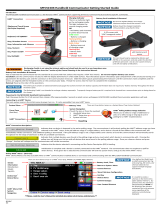
computer to the HART Tri-Loop (see Figure 3-1).
FIGURE 3-1. Tri-Loop Configurator
Software Equipment.
Disk Containing HART
Tri-Loop Configurator
Software
Laptop Computer
(not included)
HART Modem and Cables
3095.tif

HART Tri-Loop HART-to-Analog Signal Converter
3-2
Minimum Equipment and
Software
• MS-DOS based 386 computer or above
• MS DOS
®
5.0 or higher
• 640K base RAM with 8 MB extended
• Microsoft
®
Windows
®
3.1, Windows for Workgroups 3.11, or
Windows 95
• Mouse or other pointing device (optional)
• Color computer display (optional)
• HART Tri-Loop Configurator Software, HART modem, set of
modem cables
Installation Procedure
This procedure assumes that both DOS and Windows are already
installed.
NOTE
In this manual,
return
indicates to press the return or enter key.
1. Power on the computer
2. After completion of boot-up procedures, verify that the computer
is in Microsoft Windows. If the computer is at the DOS prompt
(for example, C:\), type win
return
to start Windows.
3. Insert the floppy disk containing the first HART Tri-Loop
Configurator Software into the personal computer disk drive.
4. Select F
ile, then select Run from the Program Manager to display
the Run window. Depending on the disk drive, enter either
a: setup or b: setup, then click OK.
5. Follow the directions provided by the setup utility to install the
HART Tri-Loop Configurator Software. Setup may require 3 or 4
disks, depending on the computer operating system.
NOTE
The HART communications port can be either COM1 or COM 2. The
HART communications port must be different than the mouse port.
/