Page is loading ...

MegaRAC® M300V Card
Implementer’s Reference
and User’s Guide
MAN-M300V
07/9/07

ii MegaRAC® M300V Card Implementer’s Reference and User’s Guide
© Copyright 1985-2010 American Megatrends, Inc.
All rights reserved.
American Megatrends, Inc.
5555 Oakbrook Parkway, Building 200,
Norcross, GA 30093
This publication contains proprietary information which is protected by copyright. No part of this
publication can be reproduced, transcribed, stored in a retrieval system, translated into any
language or computer language or transmitted in any form whatsoever without the prior written
consent of the publisher, American Megatrends, Inc. American Megatrends, Inc. acknowledges the
following trademarks:
AMD is a registered trademark of Advanced Micro Devices.
Other trademarks and trade names may be used in this document to refer to either the entities
claiming the marks and names or their products. American Megatrends, Inc. disclaims any
proprietary interest in trademarks and trade names other than its own.
Revision History
07/09/07 Initial release

Preface iii
Table of Contents
Revision History ......................................................................................................................................... ii
Table of Contents ...................................................................................................................................... iii
Limited Warranty ...................................................................................................................................... vi
Disclaimer ................................................................................................................................................. vi
Chapter 1 Introduction ............................................................................................................................ 1
Features .................................................................................................................................................... 2
Acronyms and Terminology ....................................................................................................................... 4
Conventions ............................................................................................................................................... 6
Reference Documents ............................................................................................................................... 7
Chapter 2 M300V Card Layout ............................................................................................................... 9
MegaRAC® M300V card Layout ............................................................................................................... 9
Chapter 3 M300V GUI ............................................................................................................................ 11
M300V GUI Overview .............................................................................................................................. 11
Initial Configuration of the MegaRAC® M300V card ............................................................................... 12
Setup your Client System’s Internet Browser ...................................................................................... 13
Default User Name and Password .......................................................................................................... 13
MegaRAC® GUI Explained ..................................................................................................................... 14
Menu Bar ................................................................................................................................................. 14
General Information Group ...................................................................................................................... 14
System Information .............................................................................................................................. 14
Server Health Group ................................................................................................................................ 15
Sensor Reading ................................................................................................................................... 15
Sensor Readings with Thresholds ....................................................................................................... 15
Event Log ............................................................................................................................................. 16
Sensor Monitoring Options .................................................................................................................. 16
Configuration Group ................................................................................................................................ 17
Alert List ............................................................................................................................................... 17
Alert List : Modify Alert ......................................................................................................................... 18
Alert List : Send Test Alert ................................................................................................................... 18
LDAP Settings ...................................................................................................................................... 19
Mouse Mode Settings .......................................................................................................................... 20
Network Settings .................................................................................................................................. 21
SMTP Setting ....................................................................................................................................... 22
SSL Configuration ................................................................................................................................ 22
User List ............................................................................................................................................... 23
Add New User ...................................................................................................................................... 24
Modify User .......................................................................................................................................... 25
Delete User .......................................................................................................................................... 25
Remote Control Group ............................................................................................................................ 26
Launch Redirection .............................................................................................................................. 26
Remote Console Shortcut Key Combinations ..................................................................................... 26
Console Redirection Window ............................................................................................................... 27
Console Redirection Window : Video .................................................................................................. 27
Console Redirection Window : Keyboard ............................................................................................ 27
Console Redirection Window : Mouse ................................................................................................. 28
Console Redirection Window : Options ............................................................................................... 28
Console Redirection Window : Device ................................................................................................. 29
Console Redirection Window : Help .................................................................................................... 29
Power Status and Control .................................................................................................................... 29
Maintenance Group ................................................................................................................................. 30

iv MegaRAC® M300V Card Implementer’s Reference and User’s Guide
Firmware Update ................................................................................................................................. 30
Languages ............................................................................................................................................... 30
Logging Out ............................................................................................................................................. 30
Chapter 4 M300V Interface Signal Specifications .............................................................................. 31
Overview .................................................................................................................................................. 31
Signal Callout Grouped by Functions ...................................................................................................... 31
LED Control Signals ............................................................................................................................. 31
Signal Group: LED Control .................................................................................................................. 31
USB Interface Signals .......................................................................................................................... 32
Signal Group: USB ............................................................................................................................... 32
Push-Button Signals ............................................................................................................................ 32
Signal Group: Buttons .......................................................................................................................... 32
Video Capture DVI-I Signals ................................................................................................................ 33
Signal Group: Video Capture DVI-I ...................................................................................................... 33
Multi-Bank Fan Control Signals ........................................................................................................... 34
Signal Group: Multi-Bank Fan Control ................................................................................................. 34
Multiplexed Fan Tach Input Signals ..................................................................................................... 34
Signal Group: Multiplexed Fan Tachometers ...................................................................................... 34
Fan Tach MUX Bank Selector Signals ................................................................................................ 35
Signal Group: Multiplexed Fan Tachometer Controls .......................................................................... 35
Single Wire Analog Voltage Sensor Signals ........................................................................................ 35
Signal Group: Single Wire Analog Sensors ......................................................................................... 35
MCard Serial Port and ICMB ............................................................................................................... 36
Signal Group: mCard Serial Port and ICMB ........................................................................................ 36
Serial Over LAN Feedback Path .......................................................................................................... 36
Signal Group: SoL Serial Port .............................................................................................................. 36
Dedicated Management Ethernet Signals ........................................................................................... 37
BMC Host Interface ID Signals ............................................................................................................ 37
Signal Group: Interface Type ID .......................................................................................................... 37
MCard Presence Detection Signal ....................................................................................................... 38
Signal Group: Card Detect ................................................................................................................... 38
System Status Signals ......................................................................................................................... 38
Signal Group: Status ............................................................................................................................ 38
System Control Signals ........................................................................................................................ 40
Signal Group: Control .......................................................................................................................... 40
I
2
C or SMBus Signals .......................................................................................................................... 41
Signal Group: I
2
C or SMBus ................................................................................................................ 41
LPC Bus Signals .................................................................................................................................. 42
Signal Group: LPC ............................................................................................................................... 42
Miscellaneous Signals ......................................................................................................................... 42
Signal Group: Miscellaneous ............................................................................................................... 42
Firmware Debugger Probe Signals ...................................................................................................... 43
Signal Group: Debug Interface ............................................................................................................ 43
Signal Group: Debug Power ................................................................................................................ 43
OPMA Hardware Resources ................................................................................................................... 44
SEEPROM Address Reservation ........................................................................................................ 44
OPMA Feature Card Power Requirements ............................................................................................. 45
OPMA Feature Card Signal Tolerance Requirements ............................................................................ 46
OPMA Signals Grouped by Function ...................................................................................................... 46
Chapter 5 OPMA Connector Specification and Pin Assignments ................................................... 49
Overview .................................................................................................................................................. 49
Pin Assignments for the OPMA Connector ............................................................................................. 49
Chapter 6 M300V Card Mechanicals ................................................................................................... 53

Preface v
MegaRAC M300V DDR2 Polarization Key .............................................................................................. 53
MegaRAC M300V Card Mechanical Form Factor ................................................................................... 54
OPMA LAN and Serial Port Connector Scheme ..................................................................................... 55
Management LAN and UART Connectors .............................................................................................. 55
Chapter 7 Serial over LAN Support ..................................................................................................... 57
Serial over LAN Support .......................................................................................................................... 57
MCARD_DETECT_L = Logic High ...................................................................................................... 58
MCARD_DETECT_L = Logic Low ....................................................................................................... 59
MCARD_AUX_SoL_CTRL_L = Logic High ......................................................................................... 60
MCARD_AUX_SoL_CTRL_L = Logic Low .......................................................................................... 61
Possible UART Configurations ................................................................................................................ 62
MegaRAC M300V Card Not Present ................................................................................................... 62
MegaRAC M300V Card Present and on SoL Mode (Default) ............................................................. 63
MegaRAC M300V Card Present and in Non-SoL Mode ..................................................................... 64
Chapter 8 Motherboard Hardware Support ........................................................................................ 65
Overview .................................................................................................................................................. 65
General Signal Termination ..................................................................................................................... 65
Fan Tachometer Read Back ................................................................................................................... 65
Fan Tach Monitoring Circuit Block Diagram ........................................................................................ 66
Fan Tach Monitoring Circuit Example .................................................................................................. 66
Fan Speed Control .................................................................................................................................. 67
Fan Speed Control Circuit Block Diagram ........................................................................................... 67
Fan Speed Control PWM-to-DC Converter Circuit Example ............................................................... 67
Clear CMOS Circuit ................................................................................................................................. 68
CMOS Clearing Circuit Example ......................................................................................................... 68
System Speaker Control Circuit .............................................................................................................. 69
Speaker Control Circuit Example ......................................................................................................... 69
Local Access Lock Out ............................................................................................................................ 70
Partial Circuit Example for Local Access Lock Out ............................................................................. 70
ACPI State Reporting .............................................................................................................................. 71
Signal Encoding for ACPI State Reporting .......................................................................................... 71
DVI–Digital Visual Interface ..................................................................................................................... 71
ICMB RS-485 Level Translation Circuit ................................................................................................... 71
Management UART Signal Level Translation ......................................................................................... 71
Management UART Signal Multiplexing .................................................................................................. 72
Support for Dedicated Management LAN ............................................................................................... 72
MCard Presence Detect and Interface ID Support .................................................................................. 72
Motherboard Support for I/O Functions ................................................................................................... 73
Motherboard Support for MegaRAC M300V SCI Interrupt Signal........................................................... 73
Motherboard I/O Terminations ................................................................................................................ 73
Chapter 9 BIOS/Firmware Considerations ......................................................................................... 75
MCard Presence Detect .......................................................................................................................... 75
Card Detect Signal States ................................................................................................................... 75
MCard IPMI Command Interface Type Detection ................................................................................... 75
Management Subsystem Host Interface Type Encoding .................................................................... 76
IPMI Command Hardware Interface Support .......................................................................................... 76
IPMI Command BIOS Interface Support ................................................................................................. 76
MegaRAC M300V Card Presence, Health and BMC Firmware Revision Reporting .............................. 77
BIOS POST Screen ............................................................................................................................. 77
System Identification ............................................................................................................................... 78
Index ........................................................................................................................................................... 79

vi MegaRAC® M300V Card Implementer’s Reference and User’s Guide
Limited Warranty
The buyer agrees that if this product proves to be defective, American Megatrends is only
obligated to repair or replace this product at American Megatrends’ discretion according to the
terms and conditions of the warranty registration card that accompanies this product. American
Megatrends shall not be liable in tort or contract for any loss or damage, direct, incidental or
consequential resulting from the use of this product. Please see the Warranty Registration Card
shipped with this product for full warranty details.
Disclaimer
This manual describes the operation of the American Megatrends MegaRAC® M300V card.
Although efforts have been made to assure the accuracy of the information contained here,
American Megatrends expressly disclaims liability for any error in this information and for
damages, whether direct, indirect, special, exemplary, consequential or otherwise, that may result
from such error, including but not limited to the loss of profits resulting from the use or misuse of
the manual or information contained therein (even if American Megatrends has been advised of
the possibility of such damages). Any questions or comments regarding this document or its
contents should be addressed to American Megatrends at the address shown on the inside of the
front cover.
American Megatrends provides this publication “as is” without warranty of any kind, either
expressed or implied, including, but not limited to, the implied warranties of merchantability or
fitness for a specific purpose.
Some states do not allow disclaimer of express or implied warranties or the limitation or exclusion
of liability for indirect, special, exemplary, incidental or consequential damages in certain
transactions; therefore, this statement may not apply to you. Also, you may have other rights
which vary from jurisdiction to jurisdiction.
This publication could include technical inaccuracies or typographical errors. Changes are
periodically made to the information herein; these changes will be incorporated in new editions of
the publication. American Megatrends may make improvements and/or revisions in the product(s)
and/or the program(s) described in this publication at any time.
Requests for technical information about American Megatrends products should be made to your
American Megatrends authorized reseller or marketing representative.

Chapter One : Introduction 1
Chapter 1 Introduction
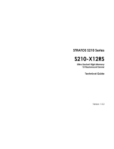
16MB Flash
Module
16MB Frame
Buffer Memory
American Megatrends Inc.
MegaRAC MG9091B
Controller Chip
DDR2 Key
OPMA Specification (Ver. 1.2)
Notice that the notch is located
closer to the leads on the right
than the leads on the left.
32 MB SOC
Memory
Reset Switch
(push to reset,
button is located
on the left side)
The MegaRAC M300V card is a high-end OPMA service processor based on AMI's MG 9091B
(Verbena II) System on Chip (SOC). The MegaRAC M300V card allows for complete server
management, with text and graphical redirection, in a 2.50' x 2.75' form factor. The MegaRAC
M300V card enables OEMs and motherboard manufacturers to easily integrate KVM server
management into their server and board designs.
The MegaRAC M300V card is a 2.5" x 2.75" daughter card module, which implements AMI's
extensive IPMI and KVM/IP technology in a management card solution compatible with all Intel
and AMD -type motherboards with OPMA connector. The module interfaces with various
components on the motherboard to manage the server efficiently.
The MegaRAC M300V card is based on AMI's MG 9091 (Verbena II) highly integrated System
on Chip (SOC). Verbena II SOC provides both Serial over LAN and KVM over LAN capability,
as well as a 10/100 Base-T LAN connection for dedicated management LAN. Serial over LAN
allows for remote operation of the server via a terminal interface, connected via an RS232 link.
KVM over LAN allows for remote server operation that adds graphical redirection to text, using
the server’s video output and keyboard and mouse inputs.
The MegaRAC M300V card features video capture of up to 1280 x 1024, applying AMI's
AAVICAII compression engine, which uses intelligent algorithms to significantly reduce network
traffic and provide high-performance redirection. The engine interfaces with the server’s DVO
video interface and USB bus.
The MegaRAC M300V card implements media redirection for the CD/DVD/ROM drive and
floppy drive at the same time. This feature enables remote installation of the operating system or
applications.

2 MegaRAC® M300V Card Implementer’s Reference and User’s Guide
Features
Feature Description
Key Features
•
2.5” by 2.75” Daughter card with OPMA connector
• MG 9091 System on Chip
• Memory: 16MB Flash ROM, 32MB SDRAM (PC100)
• Serial port - UART
• USB 2.0 for Mass Storage/Keyboard/Mouse (Composite Device)
• Integrated Watchdog Timer
• IPMB support (I2C based)
• Power Consumption: 3.3V - 800mA
AMI MG9091 Controller
•
Highly Integrated System on Chip (SoC)
• 200 MIPS 32-bit ARM CPU with MMU, 16K-I Cache, 16-D Cache
CPU
• SDRAM Controller / Static Memory Controller and Flash
• Video Processor
• Up to 1280 X 1024 Capture Engine
• 5-5-5 RGB DVO Input
• AAVICA-IIA Compression Engine
• 16Mbyte Frame Buffer SDRAM
• Ethernet: 10/100 Ethernet MAC
• USB:1xUSB 2.0 Device Controller and PHY
• Encryption Engine
• DES / Triple-DES / AES Encryption /
• Decryption compliant with NIST Standard
• AES 128/192/256-bit Keys
• Peripherals
• 5x I2C Controllers and 2x UARTs
• RTC, Timer, Watchdog Timer and Interrupt
• Controller
• 4x PWMs and 8x Tach Inputs
• 22 Dedicated GPIOs, 26 Shared GPIOs
• 200 KSPS, 8-channel ADC, 10-bit Resolution ADC
• Integrated LPC Interface
• 3X KCS Interface
• Port 80H Snoop Support
• BT Interface with 512 FIFO
• Bus master Support
• 484 Pin BGA 23x23 mm Package
KVM/IP (Console Redirection)
•
High performance redirection, up to 35
• frames per second
• Dynamic selection of 1 bit, 4 bit Gray, 7/8/16 bit color
• Resolution support:
• 1280 X 1024
• 1024 X 768
• 800 X 600
• 640 X 480
• Low network bandwidth requirement
• Auto session timeout for security
Media Redirection
•
Simultaneous floppy and CD/DVD redirection
• USB 2.0 based CD/DVD redirection with up to 18x CD speed
• Support for USB key and USB hard disk
• Auto session timeout for security
Virtual Presence and Front Panel
Redirection
•
Customizable GUI for the front panel
• Provides virtual reality of the remote server management
• LCD/LED status display
• Floppy, CD/DVD tray control
• “At-a-glance” snapshot of the server screen

Chapter One : Introduction 3
Feature Description
IPMI 2.0 Based Management
•
Manages the IPMI 2.0 based BMC present in the server
• Runs the virtual BMC stack for BMC-less systems and presents as a full
IPMI 2.0 compliant BMC
• Customizable sensor management Event Log
• Log full and partial full events
• Front panel status (LCD/LED)
• Sensor readings
• Event log full alerts
Web Based User Interface
•
Cross browser/Cross platform support
• Customizable GUI
• Added security with SSL (HTTPS)
Sophisticated User Management
•
Multiple user permission level
• Many user profiles
• Web based configuration of the user profiles
LDAP Client Support
•
Direct LDAP support from the device
• Windows Active Directory and Open-LDAP support
• Client application to extend the LDAP schema easily
SMASH and CLP Support
•
IPMI 2.0 boot option support
• Telnet based SoL
• Power control of the server
• Fully compliant with the DMTF specification
Side-Band and Dedicated NIC
•
Dedicated NIC support
Security
•
SSL (Secured Socket Layer)
• Encryption (Blowfish)
• Authentication (MD5 hash)
• SHA
• SNMP v3 (DES)
Multilanguage Support
•
Full Unicode support
• Multiple language support for multiple clients simultaneously
Web Based Configuration
•
Full configuration using Web UI
• Personality migration
• Fail-safe firmware upgrade
OEM Tools
•
AMI-PMCP for customizing the sensors
• MegaRAC Studio for customizing the GUI
• Platform Development Kit

4 MegaRAC® M300V Card Implementer’s Reference and User’s Guide
Acronyms and Terminology
This section lists the definitions of acronyms and terms used in this specification. In some of the
definitions, the IPMI Specification is referred to.
Term Definition
BIOS Basic Input Output System. This is the boot firmware on a standard PC system (including servers). It also
provides some abstraction for system hardware.
BMC Baseboard Management Controller. This is the main component of the OPMA subsystem that provides IPMI
command processing, alerting, error logging, and so on in compliance with the IPMI specification.
BT IPMI’s Block Transfer command interface.
CLI Command Line Interface. This is a text-based interface to a BMC.
CMOS Commercial Metal Oxide Semiconductor. This term refers to a battery-backed storage element found on legacy
PC systems.
COTS Commercial Off The Shelf. This refers to items that are commonly available commercially, not custom.
DDC Display Data Channel. Provides plug-and-play data to whatever device the monitor is plugged into.
DDWG Digital Display Working Group—owns DVI specification.
DVI Digital Visual Interface. A set of buses for moving video data within a system. DVI-D digitally encodes the
video data and then puts it out onto a bus. DVI-A is simply the same analog video signals seen on a standard
VGA connector. DVI-I is the union of DVI-D and DVI-A signals to provide both methods of video information
transmission over a single cable and/or connector.
FRU Field Replaceable Unit. See the IPMI specification for details.
I
2
C Inter-Integrated Circuit bus. A simple two-wire bus often used to allow system processing elements to read low
cost sensor devices. An I
2
C device interfaces to the system via the I
2
C bus.
ICMB Intelligent Chassis Management Bus. An IPMI-defined bus for connecting management processors that exist in
separate physical chassis. See the IPMI specification for details.
IHV Independent Hardware Vendor. In this document the IHV is American Megatrends Inc.
IPMB Intelligent Platform Management Bus. An IPMI-defined bus for connecting management processors that exist
in a single physical chassis. See IPMI specification for details.
ISV Independent Software Vendor. Used in this specification to refer to the manufacturer of OPMA subsystem
board firmware, OS-level drivers and OS-level applications.
JTAG Joint Test Action Group
KCS IPMI’s Keyboard Controller Style command interface
KVMoIP Keyboard, Video and Mouse over Internet Protocol. Used for implementing remote video consoles on headless
(for example, no local keyboard mouse or display) servers.
LED Light Emitting Diode
LPC A reference to the low pin count bus specification. This is a common host system interface bus for BMCs.
LUN IPMI Logical Unit Number
mCard This is the generic name for an OPMA-compliant Management Card. It is a modular, connector based
management subsystem which contains the BMC and associated hardware resources. In this document,
“mCard”, “OPMA feature card” and MegaRAC M300V card are used interchangeably.
NIC Network Interface Chip (a/k/a Ethernet controller). Typically includes an Ethernet Media Access Controller
and may also include an integrated physical layer (PHY).
ODM Original Design Manufacturer. Used in this specification to refer to the developers of motherboards that are
used in a completed server system.
OEM Original Equipment Manufacturer. Used in this specification to refer to the server system manufacturer.
OOB Out Of Band. A platform hardware management communications channel that connects a remote console
directly to the BMC. This channel is working even when the managed platform is in a soft off state.
OPMA Open Platform Management Architecture. This acronym is used in several contexts as follows:
OPMA architecture—This is the overall description of the way OPMA subsystem cards connect to and interact
with the motherboard. It includes not only the OPMA connector and associated electrical specification, but
required firmware interfaces as well as other resources located on the motherboard that are required to support
the intended usage model. The OPMA architecture is described in this specification.
OPMA subsystem—An implementation of the OPMA architecture on the motherboard taken together with an
OPMA feature card.
OPMA feature card—This is a feature board that contains the majority of the management subsystem
hardware. The term “mCard” (management card) is often used for this in the interest of brevity.
OPMA connector—This is the connector into which an OPMA feature card (MegaRAC M300V card) is
plugged to provide a given system hardware management feature set.

Chapter One : Introduction 5
Term Definition
OPMA interface—This refers collectively to all OPMA signals that are routed to and from the OPMA
connector. The term “interface” as used in this document refers to an electrical interface as opposed to software
or command interfaces.
OSPM Operating System directed Power Management
PLD Programmable Logic Device
POST Power On Self Test. In this specification, POST refers to code run at boot time by the BIOS on a server.
PWM Pulse Width Modulation
RxD Receive Data
SCI System Control Interrupt. This is a way to notify the ACPI subsystem that a device is requesting service.
SDR Sensor Data Record. See the IPMI specification for details.
SDRR Sensor Data Record Repository
SEEPRO
M
Serial Electrically Erasable Programmable Read-Only Memory
SEL System Error Log. See the IPMI specification for details.
SERIRQ Serialize Interrupt Request. See the LPC specification for details.
SMBus An I
2
C bus derivative.
SMIC IPMI‘s Server Management Interface Chip command interface
SoL Serial over LAN. The redirecting of text data to a remote text console using Ethernet as a transport. Redirected
text is typically the BMC’s CLI or system-generated text such as BIOS boot and setup screens.
SPD Serial Presence Detect (used for DRAM auto sizing)
SSIF IPMI‘s SMBus System Interface command interface
TxD Transmit Data
USB Universal Serial Bus
Zero
Impact
The ability to add an OPMA connector to an existing system for the purposes of upgrading the existing
management subsystem without requiring changes in either the existing down solution firmware or in system
BIOS.

6 MegaRAC® M300V Card Implementer’s Reference and User’s Guide
Conventions
The following table describes the conventions used in this specification.
Term Definition
Down solution This refers to a basic, BMC-based, IPMI 1.5-compliant management subsystem that is
soldered to the motherboard.
OPMA When OPMA is used as a noun, it should be taken by the reader to mean the OPMA
specification.
Upgrade kit This refers to a mCard which is used to add enhanced capabilities to a server that employs a
down solution.
Hardware signal names OPMA hardware signal names are presented in capital letters with underscores between
words. If the name ends with “L” then the signal is low true. If the name does not end with
“L”, it is high true.
Example: MCARD_CLR_CMOS_L
IPMI command names The names of all IPMI commands are presented with no spaces between the words in the
name. Only the first letter of each word is capitalized. Example: GetSystemTypeIdentifier
IPMI command parameters The names of all IPMI command parameters are presented with spaces between the words in
the name. Only the first letter of each word is capitalized unless the word is an acronym or
abbreviation.
Example: Interface ID
ms Abbreviation for millisecond(s) (1/1,000
t
h
of a second)
μs Abbreviation for microsecond(s) (1/1,000,000
t
h
of a second)
h Suffix for a number expressed in hexadecimal. Every four digit set is separated by an
underscore for readability.
Example: 1234_5678h
Note: Decimal is the default radix.
b Prefix for a number expressed in binary. Every four digits set is separated by an underscore
for readability.
Example: 1010_1101b
Note:
Decimal is the default radix.
Bit fields [x:y] Brackets designate bit fields. For example, [0] means bit zero. [3:0] refers to bits zero through
three.

Chapter One : Introduction 7
Reference Documents
The following table lists the documents referenced in this OPMA specification or are otherwise
related to the understanding of this specification.
Specification Comment
IPMI 1.5 Intelligent Platform Management Interface Specification, Version 1.5, Revision 1.1
IPMI 2.0 Intelligent Platform Management Interface Specification, Version 2.0, Revision 1.0
DVI Digital Visual Interface Specification, Version 1.0
I2C Inter-Integrated Circuit Bus Specification, Version 2.1
JTAG IEEE 1149.1
LPC Low Pin Count Interface Specification, Revision 1.1
USB Universal Serial Bus Specification, Revision 2.0

8 MegaRAC® M300V Card Implementer’s Reference and User’s Guide

Chapter Two : M300V Card Layout
9
Chapter 2 M300V Card Layout
MegaRAC® M300V card Layout
16MB Flash
Module
16MB Frame
Buffer Memory
American Megatrends Inc.
MegaRAC MG9091B
Controller Chip
DDR2 Key
OPMA Specification (Ver. 1.2)
Notice that the notch is located
closer to the leads on the right
than the leads on the left.
32 MB SOC
Memory
Reset Switch
(push to reset,
button is located
on the left side)

10 MegaRAC® M300V Card Implementer’s Reference and User’s Guide

Chapter Three : M300V GUI
11
Chapter 3 M300V GUI
M300V GUI Overview
The M300V card has a user-friendly Graphics User Interface (GUI) called the M300V GUI. It is
designed to be easy to use. It has a low learning curve because it uses a standard Internet browser.
You can expect to be up and running in less than five minutes.
This chapter allows you to become familiar with the M300V GUI’s various functions. Each
function is described in detail.
Note: Your M300V GUI may not match this document. If it does not appear to be the same, you can visit
ami.com and download the most current user’s guide.

12 MegaRAC® M300V Card Implementer’s Reference and User’s Guide
Initial Configuration of the MegaRAC® M300V card
Plug the MegaRAC® M300V card into the OPMA connector on your motherboard.
You can access the MegaRAC® M300V card from another system via the network. AMI refers to
this other system as the client system. To do this, you must know the MegaRAC® M300V card’s
IP Address. If you have installed the MegaRAC® M300V card on a network that uses DHCP, you
can search the network for the MegaRAC® M300V card. To locate and find out its IP Address,
you can run Intel Device Spy for UPnP Technologies.
Download Device Spy for UPnP Technologies from the Intel website:
http://www.intel.com/
Do a search for the following phrase:
Intel® Tools for UPnP Technologies
The download page changes from time to time, so doing a search will give you the best results.
Download the compressed file and uncompress it. The file will have a filename similar to the
following:
218892_218892.zip
The ZIP file will contain an EXE file that will have a filename similar to the following:
Intel_Tools_4UT_v1768.exe
After you run the EXE file, the Device Spy.exe file will become available. Device
Spy.exe is the file that contains the Intel Device Spy for UPnP Technologies program.
Device Spy: Intel's Universal Control Point (UCP). This tool readily tests "action" invocations and
events. Device Spy also traces packets sent to UPnP devices.
For more information on how to use Intel Device Spy for UPnP Technologies see the
documentation provided with it.
Step Action
1 Download the Intel Device Spy for UPnP Technologies program onto your remote client system.
Run the Intel Device Spy for UPnP Technologies program.
The name “MegaRAC®-M300V Device” will display in the tree under UPnP Devices.
3 Select the “MegaRAC®-M300V Device” to view its properties.
4 Click on the IP address located in the “Presentation URL” field to connect to your MegaRAC®
M300V card.
5
When prompted for the user name and password, use root for the User Name and
superuser for the Password. Both are all lower-case characters.
6 Left click the OK button. After you successfully log into your MegaRAC® M300V card, you
are greeted with the Welcome to MegaRAC® M300V card screen.
Note: When you log in using the root user name and password, you have full administrative powers. It
is advised that once you log in, you change the root password.

Chapter Three : M300V GUI
13
Setup your Client System’s Internet Browser
Yo
u must first set up Internet Explorer browser on the client system before you can redirect the
server’s console. Set up Internet Explorer’s Security Settings to allow the downloading of Signed
ActiveX controls and also allow it to run Signed ActiveX controls.
Note: At the time this document was being created, the MegaRAC® ActiveX controls were in the
process of being “signed” (by VeriSign®) so that they could be authenticated by Internet
browsers. If redirection does not operate properly, you may have to set up Internet Explorer’s
Security Settings to allow the downloading of Unsigned ActiveX controls and also allow it to run
Unsigned ActiveX controls as well.
Default User Name and Password
When you first try to access your M300V card, you will be prompted to enter a user name and
password. The default user name and password are as follows:
Field Default
User Name
root
Password
superuser
Note: The default user name and password are in lower-case characters.
Note: When you log in using the root user name and password, you have full administrative powers. It
is advised that once you log in, you change the root password.

14 MegaRAC® M300V Card Implementer’s Reference and User’s Guide
MegaRAC® GUI Explained
After you successfully log into your MegaRAC® M300V, you are greeted with the MegaRAC®
GUI.
Menu Bar
There is a menu bar located at the top of the MegaRAC® GUI. It lists the following groups:
• General Information Group
• Server Health Group
• Configuration Group
• Remote Control Group
• Maintenance Group
• Languages Group
General Information Group
This group of pages allows you to view system information.
System Information
Th
is page displays information about the firmware and device availability.
Field Description
Firmware Revision Major and minor revision of the firmware.
IPMI Version The IPMI command specification version.
Build Time The build time of the firmware.
/