Page is loading ...

BMX & FREESTYLE BIKE ASSEMBLY

FOR SERVICE
CALL TOLL FREE 1.800.451.5368
Monday - Friday 9:00 a.m. to 4:00 p.m. Eastern Standard Time
Failure to properly assemble and maintain your bicycle could result in serious injury or death.
years of enjoyment.
Carefully read and follow this manual (and any others included with this bike) before riding your bike. Please
retain this manual for future use.
This manual is provided to assist you and is not intended to be a comprehensive manual covering all aspects
of maintaining and repairing your bicycle. The bicycle you have purchased is a complex piece of equipment
that must be properly assembled and maintained in order to be ridden safely. If you have any doubts about
your ability to properly assemble your bicycle, you must have it assembled by a professional bicycle
mechanic.

Mountain Bikes. (Max weight of rider+luggage+bike = 320lbs/145kg). These bikes are intended for use off road on trails where tree-roots
and rocks are likely to be encountered. The use of a bike in hazardous conditions such as on changeable and uneven surfaces can put very
high unpredictable loads on the bike and it’s components. Lack of rider skill and experience of these conditions can further increase these
loads leading to the possibility of serious damage to the bike and injury to the rider. Wear a helmet at all times. Check your bike frequently
for loose or damaged parts and do required maintenance.
Trekking, Comfort & Cruiser Bikes. (Max weight of rider+luggage+bike = 320lbs/145kg). These bikes are intended for use on public roads,
paths or tracks that are in good condition. These bikes are NOT intended for off-road use. Wear a helmet at all times. Check your bike
regularly and do required maintenance.
Racing Bikes. (Max weight of rider+luggage+bike = 298lbs/135kg). These bikes are intended for high speed amatuer use on public roads,
paths or tracks that are in good condition. These bikes are not to be considered specialized racing bikes for use in sanctioned competitive
events. These bikes are NOT intended for off-road use. Wear a helmet at all times. Check your bike regularly and do required maintenance.
Children’s Bikes. (Max weight of rider+luggage+bike = 231lbs/105kg). These bikes are intended for use by children in safe areas that are in
good condition and free of traffic. Children must always ride within their abilities and should wear a safety helmet at all times. A parent
should check the bike regularly and do required maintenance.
RESPONSIBILITY OF THE OWNER!
Reading and following the information and instructions in this manual are essential to your ability to ride safely.
1. It is the responsibility of the owner or in the case of a younger rider the parents of the rider to be certain all assembly instructions are
followed even if the bike has been assembled by the seller or a professional assembly company.
2. Brakes are essential to safety. Be sure they are checked and working properly before each use. Remember that any mechanical system
changes condition during use and must be maintained.
3. Rules for bicycle use (bicycle laws)vairy from location to location so be certain the rider knows and understands the rules that apply to
bicycle usage in your area. Wearing a helmet and using lights and reflectors are two examples of rules that make sense as safety precau-
tions at all times.
4. Know how to operate the bicycle and all equipment on it before first use and be certain anyone else allowed to use the bike knows as
well.
5. There are many different types of bicycles and often these types are designed for different uses. Make sure you know what type unit you
have and do not exceed its service limitations. Be sure you check and understand the bicycle classifications set forth below including size
of the unit which is proper for the rider to insure good control during use. Do not overload a unit with a rider which is too heavy or too large
and do not attempt to carry loads on the bicycle in excess of its capacity. Do not attempt to use street bikes for off road riding.

OWNER’S RESPONSIBILITY continued
NOTE. Carefully read this manual and follow instructions. Your bicycle may come with additional instruction sheets that cover features
unique to your bike. Please ensure that you read and become familiar with their contents. Always wear a CPSC approved helmet when
riding your bike. Familiarize yourself with local and state traffic laws.
Any major service or adjustments on your bike should be carried out by a professional bike mechanic. If you wish to make adjustments
yourself, this manual contains important tips on how to do it. CAUTION: Any adjustments you make are entirely at your own risk. Do
NOT use your bike for freestyle and stunt riding, jumping or competitive events. Even if you are riding a mountain bike, you should know
that off-road use or any similar activities can be dangerous and you are warned that you assume the risk for personal injury, damages or
losses incurred from such use. Do not ride your bike when any part is damaged. If you are unsure how to carry out repairs or mainte-
nance on your bike it is vital that you consult a local bike mechanic for professional support.
WARNING: As with all mechanical components, the bicycle is subjected to wear and high stresses. Different materials and
components may react to wear or stress fatigue in different ways. If the design life of a component has been exceeded, it may
suddenly fail, possibly causing injuries to the rider. Any form of crack, scratches or change of coloring in highly stressed areas
indicate that the life of the component has been reached and should be replaced.
A properly fitting, CPSC approved, bicycle helmet
should be worn at all times when riding your bicycle.
In addition, if you are carrying a passenger in a child
safety seat, they must also be wearing a helmet.
The correct helmet should:
- be comfortable
- be lightweight
- have good ventilation
- fit correctly
- cover the forehead

Parts Identification Graphics .................................. 5-6
Before Riding ......................................................... 7-10
Assembly Instructions ............................................ 11-27
Maintenance
..........................................................
28-40
Warranty ................................................................ 41
WARNING / CAUTION


FREESTYLE PARTS IDENTIFICATION

RULES OF THE ROAD
In the interest of safe cycling, make sure you read and understand the owner’s manual.
Throughout this manual you will find WARNING, CAUTIONS, and NOTES or NOTICES.
WARNINGS: Pay special attention to these since failure to do so could result in injury to the rider or others.
CAUTIONS: If not followed these could result in mechanical failure or damage.
NOTES or NOTICES: These specify something that is of special interest.
Before you ride this bicycle, read this RULES OF THE ROAD section and check that all parts are installed as per this instruction manual.
If you understand how the bicycle operates, you will get the best performance. When you read this instruction book, compare the illustra-
tions to the bicycle. Learn the location of all the parts and how they work. Keep this book for future reference. Before you ride the bicycle,
check the brake and other parts of the bike. Make sure all parts are assembled correctly and working properly. Take your first ride in a
large, open, level area. If you have a problem, check the assembly instructions and follow the maintenance procedures in this book. If you
do not feel comfortable with your skills in assembling or adjusting the bike, please take your bike to a professional bike repairman.
1. WARNING ON AND OFF ROAD CONDITIONS: The condition of the riding surface is very important. If the surface is wet, or has sand,
small rocks or other loose debris on the surface, carefully decrease the speed of the bicycle and ride with extra caution. It will also take a
longer time and more distance to stop. Apply the brake earlier than normal and with less force to help keep the bicycle from sliding.
2. NOTICE: some state and local laws may require that your bike be equipped with a warning device, such as a horn or bell and a light. Do NOT
ride at night. Vision is quite limited at dawn and dusk.
3. Always wear shoes when riding a bicycle and avoid loose fitting clothes. Wear a cuff band or trouser clip to keep pants from getting caught in
the chainwheel. Long sleeves, long pants, gloves, eye protection and elbow and knee pads are also recommended.
4. CAUTION: WET WEATHER WARNING: Check your brakes frequently. The ability to stop your bicycle is critical. Roads are slippery in wet
weather so avoid sharp turns and allow more distance for stopping. Brakes may become less efficient when wet. Leaves, loose gravel and other
debris on the road can also effect stopping distance.
5. Don’t wear anything that restricts your hearing.
6. When riding, ALWAYS WEAR A CPSC APPROVED BIKE HELMET.

RULES OF THE ROAD continued
7. Obey all traffic regulations. Most traffic regulations apply to bike riders as well as automobile operators. Observe all state and local traffic
regulations, signs and signals. Check with your local police station on bicycle licensing and inspection, and where it is legal to ride your bike.
8. Keep to the RIGHT SIDE. Follow the traffic flow in a straight line close to the curb. Watch out for opening car doors and cars moving in and out
of traffic. Use caution at intersections and keep both hands on the handlebars.
9. Never carry passengers. This is dangerous and it makes the bicycle harder to control. Never carry packages that can hinder your vision or
control of the bike.
10. When riding in pairs or in larger groups, form a single line along the right side of the road. Set up a sensible distance between riders. Don’t
follow too closely.
11. Always be alert. Animals or people may dart in front of you. Give pedestrians the right-of-way. Don’t ride too close to pedestrians, and don’t
park your bicycle where it can get in the way of foot/vehicle traffic.
12. Be careful at all intersections. Slow down and look both ways before crossing.
13. Use hand signals. Always let other drivers and pedestrians know what you are going to do. Signal 100 ft. before turning unless your hand is
needed to control the bike.
14. WARNING: NIGHT TIME OPERATION: We do NOT recommend riding your bike at night. If you have an emergency that requires you to ride at
night, you must have proper lights and reflectors. NEVER ride at night without a headlight, taillight, a white front reflector, a red rear reflector, pedal
reflectors and white wheel reflectors.
15. Cover your stem, handlebar, and top tube with safety pads for additional protection.
16. Never hitch rides. Never hold onto moving vehicles while riding. Never stunt ride or jump on your bike.
17. ON AND OFF ROAD OPERATION: Avoid the following road hazards: drain grates, pot holes, ruts, soft road edges, gravel, leaves (especially
when they are wet), uneven pavement, railroad crossings, manhole covers, curbs, speed bumps, puddles, and debris call all have effect on your
riding and result in loss of control.
18. Do not ride your bicycle if the chain cover is not attached.

####
* 5/6mm hex wrench (only tool included with bike)
* Torque wrench
* Air pump & tire guage to inflate tires
* 6” adjustable wrench
* Phillips & standard screwdrivers
* A pair of pliers with cable cutting ability
BEFORE RIDING:
Your new bicycle was assembled and tuned in the factory and then partially disassembled for shipping. The following instructions will enable you
to prepare your bicycle for years of enjoyable cycling. For more details on inspection, lubrication, maintenance and adjustment of any area please refer to
the relevant sections in this manual. If you have questions about your ability to properly assemble this bicycle, please consult a professional bicycle
mechanic before riding.
TO AVOID INJURY, THIS PRODUCT MUST BE PROPERLY ASSEMBLED
BEFORE USE. WE STRONGLY RECOMMEND THAT YOU REVIEW THE
COMPLETE ASSEMBLY GUIDE AND PERFORM CHECKS SPECIFIED IN
THE OWNER'S MANUAL BEFORE RIDING.
Each bicycle has a serial number stamped into
the bottom of the frame (See Illustration). Record
this number HERE to keep for future reference.
This number can be helpful to reclaim your bike
if ever lost or stolen. THIS INFORMATION IS
ONLY AVAILABLE ON THE BIKE ITSELF. There is
no record of your serial number at the store
purchased or with our company. It is your responsibility
to record this information.
* Bicycle lubricant or grease

THERE SHOULD BE A CLEARANCE OF NO LESS THAN 1-2 INCHES BETWEEN THE
GROIN AREA OF THE INTENDED RIDER AND THE TOP TUBE OF THE BICYCLE, WHILE
THE RIDER STRADDLES THE BICYCLE WITH BOTH FEET FLAT ON THE GROUND.
THE SEATPOST “MINIMUM INSERTION” / “MAXIMUM
HEIGHT” MARK SHOULD NOT BE VISIBLE WHEN THE
SEAT POST IS INSERTED INTO THE SEAT MAST OF THE
BIKE. DO NOT RAISE THE SEAT POST BEYOND THIS
MARK. THE SEAT POST MAY BREAK CAUSING YOU TO
LOSE CONTROL AND FALL. ALWAYS CHECK TO MAKE
SURE SEAT POST ADJUSTING MECHANISM IS TIGHTENED
SECURELY BEFORE RIDING.
Arms not
overextended
Handlebar stem
height about the
same as
seat height
Pedal
bottom position
RIDING POSITION

ASSEMBLING YOUR BIKE
PREPARATION
It is important that you read this owner’s manual before you start to assemble your bicycle. WE RECOMMEND THAT YOU
CONSULT A PROFESSIONAL BICYCLE MECHANIC IF YOU HAVE DOUBTS OR CONCERNS AS TO YOUR ABILITY TO
PROPERLY ASSEMBLE, REPAIR, OR MANITAIN YOUR BICYCLE. Remove all parts from the shipping carton. Check to
make sure no parts are loose on the bottom of the carton. Carefully remove the front wheel which is attached to the side of
the bicycle for shipping. Carefully remove all other packing material from the bicycle. This includes zip ties, axle caps and
material protecting the frame.
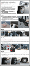
FRONT WHEEL
1. Remove the nuts, washers and wheel retainers from the front wheel axle, if
necessary. If these are not on the wheel axle, they will be included int he
hardware bag.
2. Slide the wheel onto the open ends of the fork. Slip an axle retainer onto each
end of the axle, and hook the retainers into the holes in the fork end. Loosely
install the washer onto each end of the axle (serrated end toward the retainer),
then intall the hex nut. (Note: there may be a washer head nut in place of the
washer and hex nut).
3. Center the wheel in the fork and tighten the axle nuts securely, alternating
from one side to the other.
4. Spin the wheel to make sure that it is centered in the fork and does not
wobble. If the wheel is not centered, loosen the nuts and try again.
Torque requirement: 16-20 ft lbs.

KICKSTAND
WARNING! THE KICKSTAND IS DESIGNED TO SUPPORT THE BICYCLE ONLY,
NOT THE BICYCLE AND RIDER.
If your bike is equipped with a kickstand, please follow the instructions
below.
1. Place the bicycle in an upright position.
2. Remove the top plate from the kickstand.
3. From the left side of the bicycle (opposite side from chainring), place
the kickstand in position beneath the two rear fork legs.
4. Place the top plate, flange down, onto the mounting bolt.
5. Replace the washer and nut onto the mounting bolt. Hold the kickstand
arm in an up position aligned with the frame stay, then securely tighten
the mounting bolt.
6. Leave the leg of the kickstand down so it will support the bicycle during
the rest of the assembly process.

PEDAL INSTALLATION
1. Apply a small amount of grease to the threads of each pedal. look
for the letter “L” or “R” on the side or end of each pedal spindle
(picture). Turning the spindle clockwise by hand (Picture), thread the
pedal marked “R” into the crank arm on the right (drive) side of the
bicycle. Make sure that you are not “cross-threading”. which can strip
the threads in the crank arm. If the threads do not turn easily, don’t
force them. Back the spindle out and start over. Once the pedal is
threaded into the crank arm, tighten the spindle securely to the crank
arm with a 15mm open end or an adjustable wrench.
2. Turning the spindle counterclockwise by hand, thread the pedal
marked “L” into the crank arm on the left side of the bike. Make sure
that you are not “cross-threading”. which can strip the threads in the
crank arm. If the threads do not turn easily, don’t force them. Back the
spindle out and start over. Once the pedal is threaded into the crank
arm, tighten the spindle securely to the crank arm with a 15mm open
end or an adjustable wrench.
WARNING! IMPROPERLY INSTALLED AND TIGHTENED PEDALS
CAN WORK LOOSE, DAMAGING THE BICYCLE AND CAUSING
POSSIBLE SERIOUS INJURY OR DEATH TO THE RIDER.
Torque Requirement 15-18 ft. lbs.

1. Loosen the seat clamp nuts.
2. Insert the top portion of the seat post into the seat clamp. Be sure the seat
post is completely inserted into the seat clamp and butted tightly against the
underside of the seat.
3. Tighten seat clamp nuts securely.
4. Insert the seat post (with seat attched) into the bike frame. Be sure that the
seat post is inserted past the minimum insertion line.
5. Tighten the seat post binder bolt securely at the desired height.
6. Adjust the angle of the seat so that the top of the seat is parallel to the
ground or comfortable to the rider.
7. Retighten the seat clamp nuts securely. Check for tightness by attempting to
twist the seat. If the seat is loose, be sure to tighten the clamp nuts and binder
bolt securely. Torque requirement 15-20 ft. lbs.
THE SEATPOST “MINIMUM INSERTION” / “MAXIMUM HEIGHT” MARK
SHOULD NOT BE VISIBLE WHEN THE SEAT POST IS INSERTED INTO THE
SEAT MAST OF THE BIKE. DO NOT RAISE THE SEAT POST BEYOND THIS MARK.
THE SEAT POST MAY BREAK CAUSING YOU TO LOSE CONTROL AND FALL.
ALWAYS CHECK TO MAKE SURE SEAT POST ADJUSTING MECHANISM IS TIGHT-
ENED SECURELY BEFORE RIDING. RIDING WITH AN IMPROPERLY TIGHTENED
SEAT POST CAN ALLOW THE SEAT TO TURN OR MOVE AND CAUSE THE RIDER
TO LOSE CONTROL

SEAT & QUICK RELEASE SEAT POST ASSEMBLY
THE SEATPOST “MINIMUM INSERTION” / “MAXIMUM HEIGHT” MARK
SHOULD NOT BE VISIBLE WHEN THE SEAT POST IS INSERTED INTO
THE SEAT MAST OF THE BIKE. DO NOT RAISE THE SEAT POST BEYOND
THIS MARK. THE SEAT POST MAY BREAK CAUSING YOU TO LOSE
CONTROL AND FALL.
ALWAYS CHECK TO MAKE SURE SEAT POST ADJUSTING MECHANISM IS
TIGHTENED SECURELY BEFORE RIDING. RIDING WITH AN IMPROPERLY
TIGHTENED SEAT POST CAN ALLOW THE SEAT TO TURN OR MOVE AND
CAUSE THE RIDER TO LOSE CONTROL AND FALL.
1. Loosen the seat clamp nuts.
2. Insert the top portion of the seat post into the seat clamp. Be sure the seat post is
completely inserted into the seat clamp and butted tightly against the underside of the
seat.
3. Tighten seat clamp nuts securely.
4. Insert the seat post (with seat attched) into the bike frame. Be surethat the seat post is
inserted past the Minimum Insertion Line. Review SADDLE HEIGHT guidelines on page 19.
5. Tighten the tension adjusting nut by hand and move the quick release lever to the closed
position. NOTE: Turning the tension adjusting nut clockwise while keeping the lever from
rotating reduces clamping force. Less than half a turn of the tension adjusting nut can
make the difference between safe clamping force and unsafe clamping force. You should
feel considerable resistance while moving the lever. If not, re-open and retighten the lever,
then move it to the closed position so it is in line with the top tube of the frame (as shown
in the top illustration).
6. Adjust the angle of the seat so that the top of the seat is parallel to the ground or
comfortable to the rider.
7. Retighten the seat clamp nuts securely. Check for tightness by attempting to twist the
seat. If the seat is loose, be sure to tighten the clamp nuts and binder bolt securely. Torque
requirement 15-20 ft. lbs.

Cross Tighten Clamp
Bolts For Even Clamping
HANDLEBAR STEM
NOTE: the handlebar stem has been pre-assembled to the
handlebar at the factory.
1. Remove the packing material and rotate the handlebar into an upright
position. Slightly loosen the clamp bolts to allow the handlebar to rotate
easily. After you have acheived a comfortable handlebar position,
proceed to tighten the clamp bolts to the required torque.
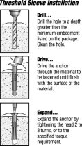
2. Insert the handlebar stem into the fork tube (head of the bike) with
the clamp portion of the stem towards the front of the bike. The stem
must be inserted far enough to hide the minimum insertion line marked
on the stem. If necessary, loosen the expander bolt to allow the stem to
fit the fork tube.
3. Place a drop of oil under the head of the expander bolt. Tighten the
expander bolt just enough to hold the stem in place.
4. Raise or lower the handlebar stem until you have reached the desired
height for your child and then position the handlebar so it is perpen-
dicular (90 degrees) to the front wheel. Next, tighten the expander bolt
to the required torque. Be sure to have inserted the stem into the fork
tube at least 2 1/2” (65mm), making certain the minimum insertion line
is not visible.
WARNING! ASSEMBLER IS CAUTIONED AGAINST THE
DANGER OF DAMAGING THE HANDLEBAR STEM ASSEMBLY
AND POSSIBLE INJURY TO THE RIDER RESULTING FROM OVER
TIGHTENING THE EXPANDER BOLT AND EXPANDER WEDGE.
EXPANDER BOLT TORQUE REQUIREMENT 10-15 ft-lbs (13-20 N-m)
CLAMP BOLT TORQUE REQUIREMENT 8-11 ft-lbs (11-15 N-m)

17
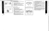
Brake Lever
Nipple
Ferrule
Grip Handlebar
Cable
Adjusting
Barrel
Side Pull
Brakes
Cable
Adjusting
Barrel
Center Bolt
Cable
Anchor
Nut
Brake Shoe
Fixing Nut
in Back
Brake
Arm
HAND BRAKES
Determine which type of brake your bike is equipped with and refer to the appropriate
assembly instructions. If your bike comes equipped with a foot brake ONLY, no brake
adjustment is required. For more information on brake adjustment and maintenance,
refer to the maintenance section of this manual.
NOTE: A greater force is required to activate the rear brake due to longer cable length. It
is advisable to mount the rear brake on the side of the stronger hand. It is important to
become familiar with the use of hand brakes. When properly adjusted, hand brakes are
an efficient braking system. Keep the rim and brake shoes clean and free from wax,
lubricants and dirt at all times. Keep brakes properly adjusted and in good working
condition at all times.
Open the brake lever and place the nipple end of the short brake cable into the lever,
then close the lever. Secure the ferrule against the lever using the cable adjusting barrel.
SIDE PULL CALIPER BRAKE
Loosen the cable anchor nut and thread the brake cable through it. Tighten the nut by
hand until it holds the cable in place. Squeeze the brake arms together against the rim of
the wheel. Loosen the nuts on the brake shoes and turn until they match the angle of the
rim. Tighten the nuts securely. Pull down on the end of the brake cable with pliers, hold
taut and securely tighten the cable anchor nut. Spin the wheel, the brake shoes should
not contact the rim at any point and should be an equal distance from the rim on both
sides. Make sure all nuts and bolts are securely tightened. Test the brake levers 20-25
times to take care of any initial cable stretch. Be sure to tightly secure the brake fixing
nut behind the fork.
WARNING! When assembling or adjusting the brakes, make sure the cable
anchor is tight. Failure to securely tighten the nut could result in brake failure
and personal injury.

18
Front U-Brake
increase
increase
increase
hex
U-BRAKES
Begin by adjusting the pads of the U-brakes using a 10mm wrench. Make sure the pad is hitting the rim and not the tire. Ideally the front
of the pad should hit the rim approximately 1mm before the rear pad.
Front U-Brake: Slide the brake cable and housing through the Housing Barrel and through the cable anchor bolt. Set the cable
clearance of 1mm between the brake pads and the rim. Tighten the cable anchor bolt. All instructions shown are if you are looking at
the bike from the front. For brake adjustments, use a 13mm box end wrench and a 5mm hex wrench. Loosen the 5mm hex bolt. For the
drive side (left) of the bike turn the spring tension nut with a 13mm box end wrench counter-clockwise to increase tension on the
spring. For the non-drive side (right), turn spring tension nut with a box end wrench clockwise to increase tension on the spring. When
the desired tension is achieved hold the tension nut with the 13mm wrench and tighten the 5mm hex bolt. The tension on each side
should be equal so that the brake arms move the same distance when the brake is activated.

Rear U-Brake
Option 1
increase
increase
hex
increase
increase
hex
Rear U-Brake Option 1: Next, tighten the Cable Carrier to the
brake cable approximately 20mm from the brake arms when
they are closed against the rim. Attach the Straddle cable to
the carrier. Hook cable end into the brake slot, pull excess
straddle cable through the cable anchor and tighten the cable
anchor. Continue with “For Both Options” below.
Option 2: Place brake housing into the frame housing
stops. Pull brake cable tightly and thread across
through the opposite cable anchor bolt. Tighten cable.
Repeat for other side. Continue with “For Both
Options” below.
For Both Options: For brake adjustments, use a 13mm open end wrench and a 5mm hex wrench and loosen the 5mm hex bolt. For
the drive side (right) of the bike turn the spring tension nut with a 13mm open end wrench counter clockwise to increase tension on the
spring. For the non-drive side (left), turn the spring tension nut with a box end wrench clockwise to increase tension on the spring.
When the desired tension is achieved, hold the tension nut with the 13mm wrench and tighten the 5mm hex bolt. The tension on each
side
should be equal so that the brake arms move the same distance when the brake is activated. PLEASE NOTE: that some BMX
frames have the U-Brake flipped and mounted below the seatstays. The direction to tension the springs will still be oriented to how the
picture is oriented.
Rear U-Brake
Option 2
WARNING! Do NOT ride the bike until the brakes are working properly. To test, apply the brakes while trying to push the
bike forward to make sure they will stop the bike
WARNING!
These brakes offer
considerable braking
power with little
leverage force and
require practice at
low speeds before
normal use.
/