Follett HCC1010AHT Installation Instructions Manual
- Category
- Ice cube makers
- Type
- Installation Instructions Manual

01113323R02
Order parts online
www.follettice.com
Horizon Elite
™
Ice Machine Installation Instructions
for Harmony
™
Top-mount Applications
HCD/HMD710AHT, HCC1010AHT, HCC1410AHT, HCC1010WHT, HCC1410WHT,
HMC1010AHT, HMC1410AHT, HMC1010WHT, HMC1410WHT,
HCE1010AHT, HCE1410AHT, HCE1010WHT, HCE1410WHT
HME1010AHT, HME1410AHT, HME1010WHT, HME1410WHT
(See model number congurator on page 2 for details.)
self-contained
Horizon top-mount ice machines
t most countertop dispensers manufactured by
Cornelius • Lancer • SerVend
801 Church Lane • Easton, PA 18040, USA
Toll free (877) 612-5086 • +1 (610) 252-7301
www.follettice.com
self-contained

2
self-contained HARMONY • TOP-MOUNT
CAUTION!
• This appliance should be connected by a qualied person in accordance with applicable codes.
• If the supply cord is damaged, it must be replaced by the manufacturer, its service agent or similarly qualied
persons in order to avoid a hazard.
• Connect to potable water supply only.
• This appliance can be used by children aged 8 years and above and persons with reduced physical, sensory,
or mental capabilities, or lack of experience and knowledge if they have been given supervision or instruction
concerning use of the appliance in a safe way and understand the hazards involved. Children should be
supervised to ensure that they do not play with the appliance.
• This appliance is intended to be used for household and similar applications such as staff kitchen areas
in shops, offices and other working environments; farm houses and by clients in hotels, motels and
other residential type environments; bed and breakfast type environments; catering and similar non-retail
applications.
• WARNING! To avoid a hazard due to instability of the appliance, it must be xed in accordance with the
instructions.
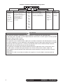
ConfigurationApplication
S RIDE™
(RIDE remote
ice delivery
equipment)
T Top-mount
425 up to
425 lbs
(193 kg)
710 up to
675 lbs
(306 kg)
1010 up to
1061 lbs
(482 kg)
1410 up to
1466 lbs
(665 kg)
1810 up to
1790 lbs
(812 kg)
2110 up to
2039 lbs
(925 kg)
V Vision™
H Harmony™
B Ice storage bin
J Drop-in
M Ice Manager
diverter valve
system
P Cornelius Profile
PR150
CondenserSeriesVoltageIcemaker
C 208-230/60/1 (icemaking head)
Self-contained only.
D 115/60/1 (icemaking head)
Self-contained and remote. If remote
unit, high side is 208-230/60/1.
E 230/50/1 (icemaking head)
Self-contained only.
F 115/60/1 (icemaking head)
Remote only. High side is
208-230/60/3.
MC Maestro™
Chewblet
®
(425 Series)
HC Horizon
Chewblet
(710, 1010,
1410, 1810,
2110 Series)
HM Horizon
Micro Chewblet
HC 1810D SVA
A Air-cooled, self-contained
W Water-cooled, self-contained
R Air-cooled, remote condensing unit
N Air-cooled, no condensing unit for
connection to parallel rack system
Chewblet
®
Ice Machine Model Number Configurations

HARMONY • TOP-MOUNT self-contained
3
87
5 6
43
21
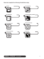
Read and complete the following 8 installation steps
Front coverInternal connection
External connection
Louvered docking assembly
Bin preparation
Site preparationUnpack
Ice transport tube

4
self-contained HARMONY • TOP-MOUNT
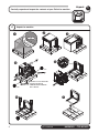
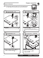
Carefully unpack and inspect the contents of your Follett ice machine.
1
Unpack
7/16"
7/16"
➊
➋
➌
➍
➎
➏
➐
DO NOT TILT ICE MACHINE
TO ACCESS BOLTS!
COMPRESSOR DAMAGE
WILL RESULT
Unpack ice machine
1. 1

HARMONY • TOP-MOUNT self-contained
5
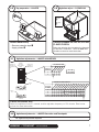
Prepare the installation site.
2
H_C1410A/W
NEMA
6-20
H_C1010A/W
NEMA
6-15
➍
➋
➌
➊
H_D710A
NEMA
5-15
1' (0,3 m)
1/4" (6,4 mm)
H_E1010A/W
‡
H_E1410A/W
‡
requires 15A circuit,
1.50 mm
2
wire
requires 20A circuit,
4.00 mm
2
wire
1" Stand pipe/Drain
3/4" MPT x 1" slip
➍
3/4" barb x 3/4" FPT
2 ft. x 1" OD
silicone tubing
Minimum 8"
radius
➌
Site preparation
2.1
Provide drainage, water supply and electrical power to within 6 feet (2m) of ice
machine in accordance with local and national codes. Outdoor installation is
not recommended and will void warranty.
Electrical
➊
• H_C1010/1410(A/W)HT 208-230/60 • H_D710AHT 115/60
• H_E1010/1410(A/W)HT 230/50
‡
Requires dedicated 15A circuit.
(H_E1010A/W requires 15A dedicated circuit 1.50 mm
2
wire, H_E1410A/W requires 20A dedicated circuit 4.00 mm
2
wire)
‡ Plug must be provided by end user & must conform to standard EN 60 335-2-24 of the end destination.
Potable water supply
➋
(3/8” push-in internal connection, 3/8” OD tubing required)
• 10-70 psi (69-483kpa)
• 45 to 90 F (7 to 32 C)
• Follett recommends the use of an in-line water ltration system (item# 00130286)
• This equipment is to be installed with adequate backow protection to comply with applicable
federal, state, and local codes
Condenser water supply for water-cooled systems
➌
(1/4” FPT inlet, 1/4” FPT outlet)
• 10 psi min.; 150 psi max. (69kpa min.; 1034kpa max.)
• 45 to 90 F (7 to 32 C)
• 1.5 gallons per minute (5.68 liters per minute)
Drain
➌
(3/4” Barb)
• Minimum 8” radius on silicone drain line. Drain line from the ice machine must have at least
1/4” per foot pitch (6,4mm/0,3m).
Installation site requirements
2.1

6
self-contained HARMONY • TOP-MOUNT
Prepare the dispenser.
3
Dispenser preparation
➊
➊
All models
• Remove protective tape from gaskets
➊
Top preparation – ALL
3.1
➋
➊
➌
➊
• Apply gaskets
➊
.
• Install coupling
➋
through bottom of
dispenser top and secure with locking nut
➌
Top preparation – ALL
3.2
Note: The instructions below only apply to 22" & 30" wide dispensers.
44" wide dispenser instructions may be found with the top kit.
➋
➊
Cornelius models only
• Remove protective tape
➊
• Apply gasket
➋
Top preparation – CORNELIUS
3.4
➋
➊
• Screw 4" (102mm) extension
➊
into
bottom of shuttle actuator
➋
Top preparation – ALL
3.3

HARMONY • TOP-MOUNT self-contained
7
➊
➋
➋
Lancer models only
• Remove protective tape
➊
• Apply gaskets
➋
Top preparation – LANCER
3.5
PRESS IN ON
THIS SIDE TO
TURN SWITCH
ON.
SWITCH
ON
SWITCH
OFF
PRESS IN ON
THIS SIDE TO
TURN SWITCH
OFF.
ROCKER
SWITCHES
(VIEW LOOKING
DOWN)
SIDE VIEW
SIDE VIEW
1
2
3
4
5
6
7
8
OFF
SWITCH
NUMBER
AGITATION FREQUENCY
NO AGITATION
10 MINUTES
20 MINUTES
30 MINUTES
40 MINUTES
50 MINUTES
60 MINUTES
70 MINUTES
80 MINUTES
90 MINUTES
100 MINUTES
110 MINUTES
120 MINUTES
130 MINUTES
140 MINUTES
150 MINUTES
5
6
7
8
O
O
O
O
O
O
O
X
O
O
X
O
O
O
X
X
O
X
O
O
O
X
O
X
O
X
X
O
O
X
X
X
X
O
O
O
X
O
O
X
X
O
X
O
X
O
X
X
X
X
O
O
X
X
O
X
X
X
X
O
X
X
X
X
SWITCH
NUMBER
AGITATION TIME
1 SECOND
2 SECONDS
3 SECONDS
4 SECONDS
3
4
O
O
O
X
X
O
X
X
X = ON
O = OFF
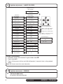
Lancer 4500 series only
Adjust the agitation time to 1 second, and the agitation frequency to 150 minutes. See Lancer
manual for more information.
Agitation adjustments – LANCER 4500 SERIES
3.7
OFF
ON
Cornelius models ED, DB, DF, IDC and
FLAVOR FUSION
Adjust the agitation timer located on the Cornelius
PC board to 1 second on, 1 hour off. Note: See
Cornelius manual for more information.
Agitation adjust. – CORNELIUS
3.6
Agitation adjustments – LANCER Sensation and Touchpoint
3.8
No agitation adjustment required

8
self-contained HARMONY • TOP-MOUNT
Major/Minor
FS-16 Setup
Config Bonus Key
Soda/Plain Water
Config Dispense Only
PC Mode
PC Time
Ice Stir Off
Ice Stir On
Sold Out
Carb Sensors
Ice Bin Sensors
Valve Code Version
Number Of Valves
Reset Defaults No Ye s
Reload Defaults?
1 2 3 4
12 0.104 0.104
1000
Ice Bin Optic
Upper Lower
Sold Out #1
Selection Sold Out
05000
On Time (MSEC)
Off On
Set PC Mode Menu
V:1 B1 DLY1
Dispense Delay
V:2 1:S 2:W 3:S 4:W
V:1 T:F M:S B:W
Bonus Key Setup
Brands Per Side
V:1 L:2 R:1
FS-16 Setup
FS-16 Setup
FS-16 Setup
FS-16 Setup
FS-16 Setup
FS-16 Setup
FS-16 Setup
FS-16 Setup
FS-16 Setup
FS-16 Setup
FS-16 Setup
FS-16 Setup
FS-16 Setup
Soda/Plain Water
OFF Time (MIN)
00150
On Time (MSEC)
01000
1000 500
34 0.104 0.104
On On On On
V:1 B:1
Sold Out #1
Off
Sold Out #1
Ver. 0.200
Lancer FS-16
Sub-CatagoryMain Menu
Initialization Screen
2nd Sub-Catagory
(Boot Up Only)
Cancel
Enter
Scrolls through Main Menu
Press "Enter" to enter sub-catagory
Moves curser to right or left
Changes value (number/letter)
Press "Enter" to enter save changes
Press "Cancel" to exit menu
➊
Lancer FS series only
• Hold down “cancel” and “left button” to get to hidden menu
➊
• Type in code 6655
• Type in 150 minutes of off time and 1010 milliseconds (1 second of time) as the preferred
setting
Note: See Lancer manual for more information
Agitation adjustments – LANCER FS SERIES
3.9
Agitation adjustments – SERVEND
3.10
SerVend models only
No agitation adjustment required.

HARMONY • TOP-MOUNT self-contained
9
P/N 307277 — Diverter plate
(single agitator Cornelius
dispensers and left-hand
dispense chute on dual-agitator
Cornelius dispensers)
P/N 307277 — Diverter plate
(single agitator Cornelius
dispensers and left-hand
dispense chute on dual-agitator
Cornelius dispensers)
Single Agitator
Dual Agitator
P/N 00996207 — Diverter plate
(right-hand dispense chute on
dual-agitator dispensers)
Dispenser diverter plate overview (Installation on next page)
3.11

10
self-contained HARMONY • TOP-MOUNT
ICE CHUTE
GATE MOUNTING PLATE
GASKET
STORAGE HOPPER
ICE DIVERTER
10-32 WASHER
10-32 NUT
FLANGE EXTENDS INTO
STORAGE HOPPER
THROUGH GATE
OPENING
APPLY RTV TO THIS
SURFACE TO SEAL
TO HOPPER GATE
MOUNTING PLATE
ICE CHUTE
COVER
Cornelius ED, DF and DB series only
These dispensers require the installation of an ice diverter at the dispenser opening.
• Disassemble chute assembly
• Discard factory restrictor plate
• Replace with alternate diverter plate (supplied)
Dispenser diverter plate installation – CORNELIUS ED, DF and DB SERIES
3.12
Agitation adjustments – Cornelius IDC and Flavor Fusion
3.13
These dispensers require modications for compatibility with Chewblet ice. Agitation
times must be set to 1 second ON, 1 hour OFF and the ice restrictor plate must
be adjusted to the fully open position. See your beverage supplier for these
modications.

HARMONY • TOP-MOUNT self-contained
11
Louvered docking assembly
4
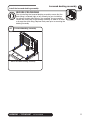
Install the louvered docking assembly.
• Mount louvered docking assembly
Louvered docking assembly
4.1
Prior to installing the louvered docking assembly, ensure that the
drain tting is oriented (right or left) correctly for your installation.
An optional straight drain tting is also supplied. You may need to
remove the back panel of the docking assembly in order to re-orient
or change the drain tting. Replace back panel prior to mounting the
docking assembly.
BEFORE PROCEEDING

12
self-contained HARMONY • TOP-MOUNT
➋
➌
➊
Hot Water
160 F (71 C)
Ice transport tube
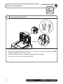
Install the ice transport tube.
5
Ice transport tube installation
5.1
• Install supplied ice transport tube insulation
• Heat end of transport tube in cup of 160 F (71 C) hot water to soften and spread with pliers
➊
before making connection to ease assembly
• Connect ice transport tube to coupling on louvered docking station
➋
• Connect ice transport tube to shuttle actuator
➌

HARMONY • TOP-MOUNT self-contained
13
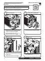
Connect utilities to louvered docking assembly.
6
External connections
➊
➏
➌
➋
➐
➑
3/4" barb x 3/4" FPT
1" Stand pipe/Drain
2 ft. x 1" OD
silicone tubing
Minimum 8"
radius
3/4" MPT x 1" slip
➍
➎
➌
➋
➊
➏
3/4" barb x 3/4" FPT
1" Stand pipe/Drain
2 ft. x 1" OD
silicone tubing
Minimum 8"
radius
➍
3/4" MPT x 1" slip
➎
Air-cooled ice machines only Water-cooled ice machines only
6.1
6.2
• Rough-in ice machine potable water
supply
➊
.
3/8” push-in connection will be made at
shut-off valve inside machine
• Remove access panel if necessary
➋.
• Connect the silicone tubing to the ice
machine 3/4” drain barb
➌
.
• Assemble the 3/4” barb x 3/4” FPT to the
3/4” MPT x 1” slip. Connect the other end
of the silicone tubing to the 3/4” barb
➍
.
• Connect the 1” slip tting to the 1” stand
pipe/drain
➎
.
Note: Minimum 8” radius on silicone
drain line. Drain line from the ice machine
must have at least 1/4” per foot pitch
(6,4mm/0,3m).
• Apply Petrol-gel to barbed drain tting
➏
• Replace access panel.
• Rough-in ice machine potable water
supply
➊
.
3/8” push-in connection will be made at
shut-off valve inside machine
• Remove access panel if necessary
➋.
• Connect the silicone tubing to the ice
machine 3/4” drain barb
➌
.
• Assemble the 3/4” barb x 3/4” FPT to the
3/4” MPT x 1” slip. Connect the other end
of the silicone tubing to the 3/4” barb
➍
.
• Connect the 1” slip tting to the 1” stand
pipe/drain
➎
.
Note: Minimum 8” radius on silicone
drain line. Drain line from the ice machine
must have at least 1/4” per foot pitch
(6,4mm/0,3m).
• Connect cooling water supply
➏
and
return
➐
• Apply Petrol-gel to barbed drain tting
➑
• Replace access panel.

14
self-contained HARMONY • TOP-MOUNT
Connect louvered docking assembly to ice
machine.
7
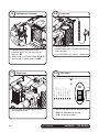
Internal connections
Air-cooled ice machines – follow steps 7.1 through 7.5.
CAUTION
• Plug must be accessible after nal installation.
• H_E1410A/W 230/50/1 requires a 20A circuit (4.00 mm
2
wire)
• Remove twist tie
• Carefully pass cord thru opening and plug
into wall outlet
• For H_E units, install a suitable plug
Power cord
7. 3
➊
➋
• Slide ice machine into louvered docking
assembly ensuring that drain tube is fully
seated on barbed drain tting
➊
• Insert ice transport tube all the way into
coupling and tighten nut rmly
➋
Ice transport tube
7. 1
➊
• Insert potable water line into valve
➊
Potable water and drain lines
7. 2
• Position plate into opening and secure
with supplied screw
Power cord
7. 4

HARMONY • TOP-MOUNT self-contained
15
➊
• Insert potable water line into valve
➊
Potable water and drain lines
7. 8
In
Out
• Install ice machine cooling water lines to
louvered docking assembly
Cooling lines
7. 6
➊
➋
• Slide ice machine into louvered docking
assembly ensuring that drain tube is fully
seated on barbed drain tting
➊
• Insert ice transport tube into coupling and
tighten nut rmly
➋
Ice transport tube
7. 7
Water-cooled ice machines – follow steps 7.6 through 7.12.
CLEANER FULL
DRAIN CLOG
HIGH PRES
HIGH AMPS
SERVICE
MAINT/CLEAN
LOW WATER
TIME DELAY
SLEEP CYCLE
MAKING ICE
LOW BIN
POWER ON
CLEAN
TDS
HIGH
LOW
• Set the TDS switch on the electrical box:
HIGH: for extended service life
LOW: for low-scale water
TDS switch
7. 5

16
self-contained HARMONY • TOP-MOUNT
• Position plate into opening and secure
with supplied screw
Power cord
7. 11
• Remove twist tie
• Carefully pass cord thru opening and plug
into wall outlet
• For HCE/HME units, install a suitable plug
Power cord
7. 1 0
➊
➋
• Connect cooling water lines to ice
machine
(Water "Out" connects to water
regulator.)
➊
• Water valve is set at the factory. DO NOT
remove seal or adjust water valve
➋
Cooling lines and power
7. 9
CLEANER FULL
DRAIN CLOG
HIGH PRES
HIGH AMPS
SERVICE
MAINT/CLEAN
LOW WATER
TIME DELAY
SLEEP CYCLE
MAKING ICE
LOW BIN
POWER ON
CLEAN
TDS
HIGH
LOW
• Set the TDS switch on the electrical box:
HIGH: for extended service life
LOW: for low-scale water
TDS switch
7. 1 2

HARMONY • TOP-MOUNT self-contained
17
➋
➊
➌
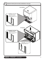
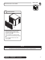
• Slide ice machine cover over machine
ensuring that tabs on back of cover
slip under louvers on back of louvered
docking assembly
➊
• Insert and tighten two screws through
cover and into louvered docking assembly
➋
• For air-cooled machines only, install
plastic grill
➌
Install front cover
Front cover
Install front cover to ice machine.
8
NOTICE
Ice machine MUST be sanitized prior to operation!
Consult Operation and Service Manual provided with ice machine for sanitizing instructions.
8.1

18
self-contained HARMONY • TOP-MOUNT
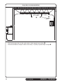
➊
➋
max. 2 ft (0,6m)
1' (0,3m)
1/4" (6,4mm)
• Pitch ice transport tube to allow melt water to drain towards ice machine
➊
• Secure insulated ice transport tube at least every 2 ft (0,6m) to prevent dips or traps
➋
Long tube run recommendations

HARMONY • TOP-MOUNT self-contained
19

01113323R02
© Follett LLC 4/18
801 Church Lane • Easton, PA 18040, USA
Toll free (877) 612-5086 • +1 (610) 252-7301
www.follettice.com
Horizon, Horizon Elite, Maestro, Harmony, Ice Manager, SafeCLEAN, Sani-Sponge and Vision are trademarks of Follett LLC.
Chewblet, RIDE and Follett are registered trademarks of Follett LLC, registered in the US.
-
 1
1
-
 2
2
-
 3
3
-
 4
4
-
 5
5
-
 6
6
-
 7
7
-
 8
8
-
 9
9
-
 10
10
-
 11
11
-
 12
12
-
 13
13
-
 14
14
-
 15
15
-
 16
16
-
 17
17
-
 18
18
-
 19
19
-
 20
20


Follett HCC1010AHT Installation Instructions Manual
- Category
- Ice cube makers
- Type
- Installation Instructions Manual
Ask a question and I''ll find the answer in the document
Finding information in a document is now easier with AI
Related papers
-
Follett Horizon Elite HCD2110NMS Installation Instructions Manual
-
Follett Horizon Elite HCE1010WHS Installation Instructions Manual
-
-
-
Follett Horizon Elite Chewblet HCD1010RBT Installation Instructions Manual
-
-
-
-
-
Follett H_D700AHS Installation Instructions Manual
Other documents
-
 Cornelius DF150 User manual
-
Scotsman Ice Slide for ED/DF200/250 Dispensers - 17-3069-01 Operating instructions
-
 Cornelius Nordic Elite series User manual
-
-
MULTIPLEX G Series Cuber Owner Instruction Manual
-
Manitowoc M-150 User manual
-
Cornelius IDC 255 Progate Drive Thru Unit User manual
-
Toro Multi-Outlet Manifold Catalogue
-
 IMI Cornelius, Inc. IDC 255 User manual
-
 Cornelius Flavorfusion Ice Drink Dispenser User manual


