All measurements are subject to accepted
manufacturing tolerances.
To ensure accuracy please check actual product dimensions before drilling for installation.
The manufacturer reserves the right to change specications at any time without giving prior notication.
This product should be installed by a qualied plumber. Local authority, Water Board, and Building
Regulations may apply to the installation of this product, and you should consult the appropriate bodies
on these requirements.
Issue No. 0
Date of Issue: 20.03.23
Urbane ll Bidet Close-
Coupled 4.5/3 litre Cistern
IMPORTANT
TO ACHIEVE A SATISFACTORY 4.5/3L FLUSH
PERFORMANCE AND A 4 STAR WATER EFFICIENCY
RATING THE CISTERN MUST BE MATCHED WITH A
COMPATIBLE CAROMA SMARTFLUSH 4.5/3L
TOILET PAN.
Flexible hose
(to cistern inlet)
[not supplied]
Flexible hose
(to bidet seat)
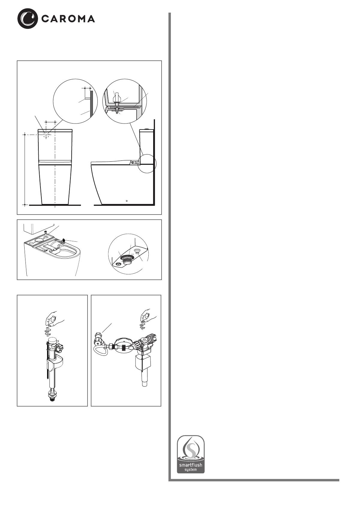
Bottom Inlet Valve Detail
Float Arm Adjustment Screw
Increase
water
level
Decrease
water
level
Fig. 3
Foam Seal Position and
Bottom Inlet Cistern Hose Fixing
Fig. 2
Fig. 4
Fig. 1
Urbane ll Bidet Cleanush® Easy Height
Wall Faced Close Coupled Toilet Suite
Note: The inlet valves are suitable for dynamic ow pressures of 30 kPa to 1000 kPa.
Note: Refer to Urbane II Bidet Cleanush Wall Faced Close Coupled Pan installation
instructions for water inlet connection details.
Stop Valve and Back Entry
Valve Detail
Increase
water
level Decrease
water
level
CISTERN FIXING PROCEDURE
Standard right hand bottom inlet (Internal overow only) installation
The inlet valve can be changed from left to right or vice versa.
Note: The cistern xes directly to the pan with a robust base xing system
without the need for wall xing.
1- Ensure the foam seal at base of cistern is securely attached to cistern
base, as detailed in Fig. 2.
2- Connect exible hose (for cistern) to inlet valve, as detailed in Fig. 2.
Position cistern onto pan and align the cistern xing holes with the
threaded xing holes located in the cistern platform.
3- Fit the seals into the winged xing bolts, as detailed in Fig. 1. Twist and
remove main top section of outlet valve to access bottom of cistern.
4- Insert the winged xing bolts through the cistern xing holes into the
threaded xing holes located in the pan. Gradually tighten the left and
right hand nuts by hand to rmly secure the cistern to pan, as detailed in
Fig. 1.
5- Flush the lines before connecting the exible hose to the stop tap.
6- Adjusting water level: Turn on water mains. Open the cistern stop valve
and check the operation of the mechanisms and valve. Adjust water
level to the water level mark inside the cistern by simply turning the oat
arm adjustment screw in a clockwise or anti clockwise direction as
detailed in Fig. 3.
7- Fit cistern lid to check push button operation to complete installation.
IMPORTANT: THE STANDARD INLET VALVE IS FITTED WITH A LINE
STRAINER. ITS TAIL IS CENTRALY LOCATED TO ALLOW EASY
REMOVAL FOR CLEANING. THIS TAIL FITS EASILY INTO THE COPPER
CONNECTION PIPE. INSTALLATION OF THE CISTERN WITHOUT THE
STRAINER CAN LEAD TO DAMAGE OF THE INLET VALVE FROM THE
WATER-BORNE CONTAMINANTS LEADING TO CISTERN MALFUNCTION.
Back Entry Installation
1- Securely attach the self-adhesive foam seal around the outlet on the
base of cistern, as detailed in Fig. 2. Remove inlet valve to gain access
to the right hand cistern xing hole.
2- Position cistern onto pan, and align the cistern xing holes with the
threaded xing holes located in the cistern platform.
3- Ensure that the back inlet water connection nipple is aligned with the cut
out in the back of the cistern. Fit the seals onto the winged xing bolts.
4- Insert the winged xing bolts through the cistern xing holes into the
threaded xing holes located in the pan. Gradually tighten the left and
right hand nuts by hand to rmly secure the cistern to pan, as detailed in
Fig. 1.
5- Fit cistern stop valve (supplied) to the 1/2” B.S.P. nipple in the wall using
approved thread seal, in the downward angled position as detailed in
Fig. 4. Connect one end of exible hose to cistern stop valve.
Note: Flexible hose assemblies shall not be submerged.
6- Ret the inlet valve into position.
7- Flush the lines and ensure the hose is not rubbing against the inside of
the cistern.
8- Turn on water mains. Open cistern stop valve and check for leaks and
operation of mechanisms and valves. Ensure there is no leakage from
the cistern into the pan.
9- Adjust water level to the 4.5 litre water level mark inside the cistern by
simply turning the oat arm screw in a clockwise or anti-clockwise
direction, as detailed in Fig. 4.
10- Fit cistern lid to check push button operation to complete installation.
Cistern
stop valve
Nut
Foam
Seal
Setout position for
1/2" B.S.P. Nipple
780
Centre of back inlet connection
100
22 mm
projection from
nished wall
1/2" B.S.P.
Nipple
Finished wall
Winged
xing bolt
Seal
Cistern
Pan Captured
nut toggle
Foam
seal
PLUMBERS' INSTALLATION
INSTRUCTIONS
PLEASE READ CAREFULLY BEFORE INSTALLATION
REFER TO URBANE II BIDET CLOSE-COUPLED PAN
INSTRUCTIONS FOR BOTTOM INLET SET-OUT
Inlet valve
connection end


