2
(N) 1
(L)
GYBNBU BK
2
(N) 1
(L)
GYBNBU BK
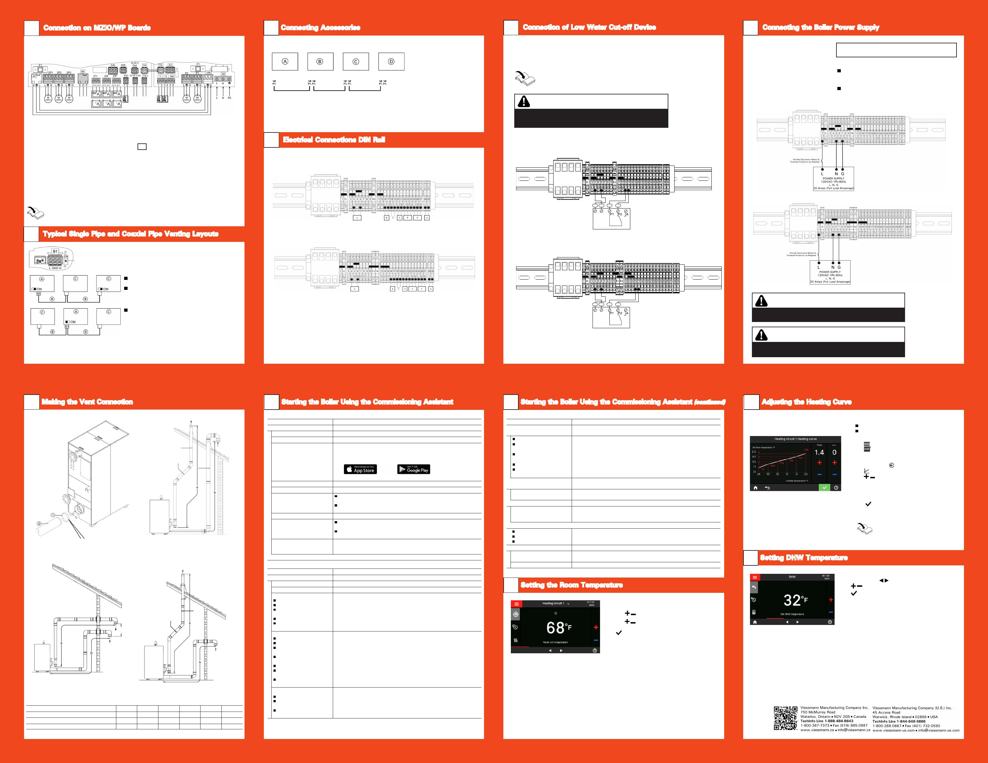
In the delivered condition, the slope of the
heating curve is set to 1.4, the level of the
heating curve is set to 0.
Making the Vent Connection
16
Setting DHW Temperature
20
Scan for
digital copy
of this
document
Refer to the “Operation” section of the
Operating Instructions for more detail.
Starting the Boiler Using the Commissioning Assistant (continued)
17
Typical Radiant = 0.6 slope & 0 curve set point
Typical Baseboard = 2.4 slope & 0 curve set point
Typical Fan Coil = 0.8 slope & 15 curve set point
6175 799 - 01
Factory setting:
“Slope”: 1.4
“Shift”: 0
Tap the following buttons:
1.
2. “Heating”
3. Select “heating zone or heating circuit”.
4. Select a heating zone or heating
circuit, e.g. “Heating circuit 1”
5. “Heating curve”
6. for the required value for “Slope”
and “Shift” respectively.
The graph displayed clearly shows the
change in the “Heating curve” as soon as
you alter the value for the “Slope” or“Shift”.
7. to confirm
Note: The heating curve can only be
adjusted in weather-compensated operation.
Note: Not valid for systems with a DHW tank with
temperature switch (e.g. Aquastat).
The factory settings 122°F (50°C).
Note: For reasons of good hygiene, you should not set
the DHW temperature lower than 122°F (50°C).
Tap the following buttons:
1. If applicable, for the “DHW” default display
2. for the required value
3. to confirm
By setting the “Heating curve”, you influence
the supply temperature provided by the boiler.
To ensure your rooms are heated optimally at
any outside temperature, you can adjust the
“Shift” and “Slope” of the “Heating curve”.
Adjusting the Heating Curve
19
Starting the Boiler Using the Commissioning Assistant
17
1. Tap the header bar and select desired heating
circuit.
2. Tap .
3. Tap for either reduced,
standard, or
comfort to adjust
temperature set point.
4. to confirm, this will take you back to the
home screen.
Electrical Connections DIN Rail
13
Accessories with direct power supply
Legend
A Lead boiler
B Mixing valve extension kit
C Mixing valve extension kit
D EM-EA1 extension and/or EM-P1 extension
jF PlusBus
Overview of terminal block connections
Legend
A Low water cut-off power supply
B Low water cut-off feedback
C Flue gas damper for common venting feedback
(factory installed jumper)
D Flue gas damper for common venting power supply
E Boiler isolation valve (power open spring return)
F Boiler pump power supply
G Boiler pump modulation signal (0-10VDC)
F1 Fuse 6.3 (slow) 120VAC
DIN rail CI2 399 to 1000
DIN rail CI2 1500/2000
F1 F1
F1
F1 F1
Connection on MZIO/WP Boards
10 Connection of Low Water Cut-off Device
14
Connecting Accessories
12 Connecting the Boiler Power Supply
15
1. Make connection for (LWCO) switching contact at terminals 16 and 17.
2. Power supply for low water cut-off device made at terminal 4 and terminal 6.
For additional information refer to the Installation Instructions.
Legend
A Boiler DIN rail
B Low water cutoff (typical)
A
B
A
B
CI2 399 to 1000
CI2 1500 and 2000
Note: The boiler is supplied with a LWCO wiring harness.
CAUTION
The diagram shown is only a simplified conceptual drawing of a typical
low water cut off (LWCO) device. Refer to the manual specific to the
device for interconnection details.
WARNING
Incorrectly executed electrical installations can lead to injuries from
electrical current and result in appliance damage.
WARNING
The control must be grounded.
Ensure that ‘L’, ‘N’ and ‘G’ are not interchanged.
IMPORTANT
Electrical installations must comply with the latest edition of:
In the U.S.A., the National Electrical Code (NEC),
ANSI/NFPA 70 and any other state, local codes and/or
regulations.
In Canada, the Canadian Electrical Code (CEC),
CSA C22.1 Part 1 and any other province, territory,
local codes and/or regulations.
CI2 399 to 1000
CI2 1500 and 2000
Note: For further information on the connections,
see the following chapters.
F2
Wiring panel
fÖ Power cable DIN rail
P1 Output 120V for:
DHW pump
P2 Output 120V for:
Heating circuit pump for heating circuit
without mixing valve A1 in conjunction with
low loss header and heating circuits with
mixing valve or DHW recirculation pump
lH External call for heat
! Outside temperature sensor, terminals 1 and 2
% Tank temperature sensor or temperature
switch such as an Aquastat, terminals 3 and 4
lA CAN BUS connection
jF PlusBus
F1 Fuse 6.3 A (slow), 120V
F2 Fuse 1 A (slow), 120V
Overview of connections to the wiring panel
and MZIO
Switch
If the boiler is not integrated into a CAN bus system:
Switch A must not be set to “ON”.
If the boiler is integrated in a CAN bus system
and is located at the beginning or end of this system
(not in the middle): Set switch A to “ON” (switched on).
If the boiler is integrated in a CAN bus system
and is not located at the beginning or end of this
system: Do not set switch A to “ON” (switched off).
MZIO
ZP1 Zone 1, pump
ZP2 Zone 2, pump
ZP3 Zone 3, pump
66 Potential-free changeover contact S
Normally closed (NC) O
Normally open (NO) P
COM
ZI1 Zone 1 or safety input 1
ZI2 Zone 2 or safety input 2
ZI3 Zone 3 or safety input 3
CAI Combustion air interlock
DIS Digital input (burner lockout)
TS1 Low loss header sensor
0-10V OUT Output 0-10V
(burner modulation feedback)
0-10V IN Input 0-10V
Legend
A Boiler
B CAN bus cable
C Other subscribers
Typical Single Pipe and Coaxial Pipe Venting Layouts
11
Legend
A Flue vent collar coupling (supplied with boiler)
B Approved venting (field supplied)
Flue
Air
Two pipe - vertical exhaust/vertical intake
a - Equivalent exhaust length
b - Equivalent air intake length
Flue
Air
Flue
Air
Min. 36 in.
(915 mm)
Two pipe - horizontal exhaust/horizontal intake
a - Equivalent exhaust length
b - Equivalent air intake length
Two pipe - vertical exhaust/ horizontal intake
a - Equivalent exhaust length
b - Equivalent air intake length
Commissioning assistant sequence Explanations and references
Commissioning
Language Factory setting: English
With programming unit If commissioning is to be carried out at the programming unit of the boiler.
With software tool The boiler automatically switches on the WiFi access point.
Further commissioning steps according to the instructions of the software tool
used (e.g. “Viguide”)
Note: Apps for commissioning and service are available for iOS and Android devices.
Cascade systems can only be commissioned using the software tool.
Units of measurement
Date and time Set the current time.
Operating mode
Weather-compensated operation
The outside temperature sensor must be connected.
Constant operation
Operation with constant supply temperature
Gas type If operating with LPG, switch to “LPG” (the delivered condition is Natural Gas)
Flue system type
Single connection
Only one boiler is connected to the flue system (factory setting).
Multiple connections
Several boilers are connected to the flue system (common venting).
Flue length adjustment Specification of the effective flue and ventilation air length. To determine the
effective flue and ventilation air length, see page 43, chapter “Matching the
burner output to the flue system”.
If no further settings are to be performed, the commissioning assistant can now be closed.
Commissioning assistant sequence Explanations and references
System scheme
Heating circuit 1 Heating circuit without mixing valve
Heating circuit 2, 3 ... Heating circuits with mixing valve
DHW
Not available
Tank with one sensor
Tank with one sensor and
DHW recirculation pump
Tank with temperature switch
Tank with temperature switch
and DHW recirculation pump
Settings for DHW heating according to the system components
System without DHW heating
System with DHW tank with 1 tank temperature sensor
System with DHW tank with 1 DHW tank temperature sensor and
DHW recirculation pump
System with DHW tank with temperature switch (such as an aquastat)
System with DHW tank with temperature switch, (such as an aquastat) and DHW
recirculation pump
Low loss header/buffer tank
Not available
Low loss header, heating only
DHW heating upstream of
low loss header
DHW heating downstream of
low loss header
Buffer tank, heating only
DHW heating upstream of
buffer tank
DHW heating downstream of
buffer tank
Settings for the consumer circuits according to the system components
There is no low loss header or heating water buffer tank in the system.
System with low loss header, without DHW heating
DHW heating with e.g. separate DHW tank connected upstream of the low
loss header
DHW heating with e.g. separate DHW tank connected downstream of the low
loss header
System with heating water buffer tank, without DHW heating
DHW heating with e.g. separate DHW tank connected upstream of the heating
water buffer tank
DHW heating with e.g. separate DHW tank connected downstream of the
heating water buffer tank
Heating zone/safety input
Heating zone 1
Heating zone 2
Heating zone 3
(based on boiler application type)
Not available, or temperature controller or safety input 1
Not available or temperature controller or safety input 2
Not available or temperature controller or safety input 3
Commissioning assistant sequence Explanations and references
Floating contact: Function
selection plug 96
If a contact has been connected to plug 96.
No function
External demand, DHW
circulation pump
External demand
(based on boiler application type)
External blocking
Heat demand
(based on boiler application type)
Push button function, DHW recirculation pump runs for 5 min.
Boiler demand with adjustable target supply temperature
(parameter 528.0) and target primary pump speed (parameter 1100.2)
Call for heat is shown in the display/menu as “Heating zone 4”.
EM-EA1 (DIO): Function selection
(based on boiler application type)
If an EM-EA1 extension (DIO electronics module) is connected as a function
extension.
Functions Selection of the connected function according to the table in the EM-EA1 exten-
sion installation instructions.
Remote control units
(based on boiler application type) Set the type of remote control and subscriber no. as assignment to the respective
heating circuit. Up to 4 heating circuits can be assigned to one remote control unit.
It is not possible for several remote controls to act on one heating circuit.
“Primary pump”
No pump
Boiler circuit pump
Boiler circuit pump
On/off control
0 - 10V modulation control
Maintenance
Interval in burner hours run until
next maintenance
Interval adjustable in steps of 100 h.
Interval until next maintenance Interval adjustable to 3, 6, 12, 18 or 24 months.
Setting the Room Temperature
18
When connecting accessories observe
the separate installation instructions
provided with them.
Vertical intake and exhaust
Vitocrossal 200 CI2 Boiler model 399 500 750 1000 1500 2000
Boiler flue collar (internal diameter) in. (mm) 4 (104.2) 4 (104.2) 6 (155) 6 (155) 6 (155) 8 (205.2)
Combustion air intake diameter in. (mm) 4 (104.2) 4 (104.2) 6 (155) 6 (155) 6 (155) 8 (205.2)
Max. total equivalent length (a+b) ft. (m) 198 (60) 198 (60) 198 (60) 198 (60) 198 (60) 198 (60)


