4
Specifications
Dial: White on black, dual scale, °F and °C standard, 4-1/2 in. (114 mm)
diameter
Power Requirements (Operating Voltages):
MDTM89-A: 100 to 350* VDC, CD ignition, negative ground (FET out-
puts)
MDTM89-E: 100 to 350* VDC, CD ignition, negative grounds (FET
outputs)
MDTM89-B: 100 to 350* VDC, CD ignition, negative or positive ground
(SCR outputs)
MDTM89-C: 12 to 24 VDC, negative ground, 15 milliwatts (FET outputs)
MDTM89-D: 120 VAC (MDTM89-C with 120 V isolation module #IT-1)
(FET outputs.) Model NOT approved by CSA
Power Consumption: CD ignition: 350 μa @ 100V; 120 VAC: 0.6 watts;
24 VDC: 0.5 watts
Outputs:
Model B: Output turns on above trip point; output turns off when power is
switched off; two (2) isolated SCR outputs, 0.5 amp @ 250 VDC
Models A, C and D: Output turns on above trip point; output turns off
below trip point; two (2) isolated FET outputs, 0.5 amp @ 250 VDC
Model E: Output one turns on above trip point, output turns off below trip
point: output 2 turns on below trip point, output turns off above trip point:
two (2) isolated FET outputs, 0.5 amp @250 VDC
Ambient Cold Junction Compensation Range: 32° to 122° F (1° C
from 0° to 50° C)
Operating Temperature: -4° to 158° F (-20° to 70° C)
Storage Temperature: -40° to 300° F (-40° to 150° C)
Case: Die-cast aluminum
Reset Differential: FET models: decreases 3 degrees (°F or °C)
SCR model: Turn input power off to reset
Measurement Range: Monitor range 0°-1999° F or ° C (specify F or C
in part number)
Accuracy: With J-type thermocouple: from 150°-1200° F (66°-649° C)
±1.5% of reading. With K-type thermocouple: from 400°-2000° F (204-
1076° C) ±1.5% of reading. At calibration temperature.
Laboratory Approvals: CSA approved for Class I, Division 2, Group D,
hazardous locations
Thermocouple Lead Length:
150 ohm lead resistance affects monitor accuracy less than 1°
Trip Point Accuracy: ±3° F (±2° C) of reading
Trip Point Adjustment Range: 0-1999 degrees
*Approved for CD ignition, 80–250 VDC.
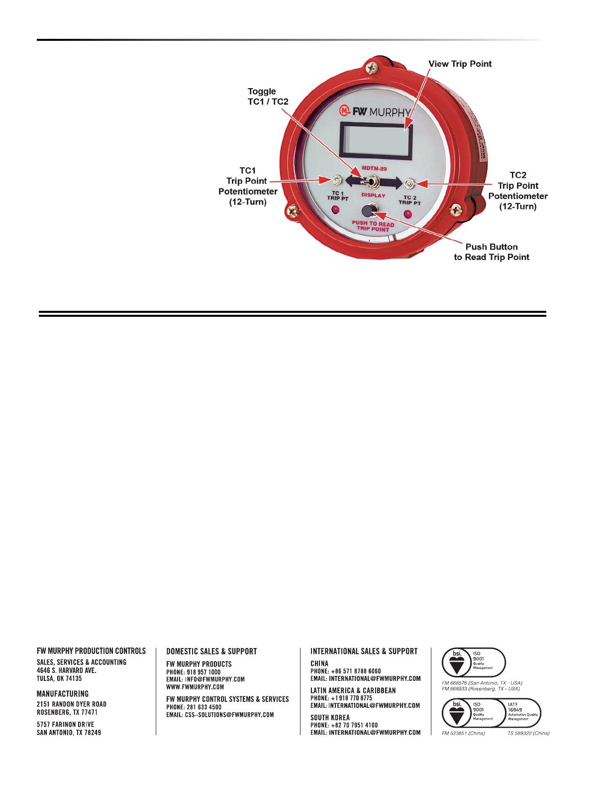
Trip Point Adjustments
1. Power up the temperature monitor by
turning on power or by starting engine.
2. Set the display toggle switch to the
TC1 position.
3. Press the button and read the trip
point in display.
4. Rotate the trip point potentiometer
TC1 until the display indicates the
desired trip point temperature for TC1.
5. Set the display selector switch to TC2
position.
6. Press the button and read the trip
point in display.
7. Rotate the trip point potentiometer
TC2 until the display indicates the
desired trip point temperature for TC2.
In order to consistently bring you the highest quality, full-featured products, we reserve the right to change our specifications and designs at any time.
FW MURPHY product names and the FW MURPHY logo are proprietary trademarks. This document, including textual matter and illustrations, is copyright
protected with all rights reserved. (c) 2022 FW MURPHY. A copy of our typical warranty may be viewed or printed by going to www.fwmurphy.com/warranty.


