Quick Start Guide
– 3 –
1. Connect the ground wire / protective earth.
2. Connect the -44 – -60 VDC wire.
3. Connect the DC return wire.
Make Network Connections
QSFP-DD/QSFP28/SFP28 Ports
Install transceivers and then connect fiber optic cabling to the transceiver
ports. Alternatively, connect AEC/AOC/DAC cables directly to the QSFP-
DD/QSFP28/SFP28 slots.
The following transceivers are supported in the QSFP-DD ports:
400GBASE-SR8, DR4, FR4, AEC cable
The following transceivers are supported in the QSFP28 ports:
100GBASE-SR4, PSM4, LR4, ER4, ZR4, CR4, AOC
40GBASE-SR4, PSM4, LR4
The following transceivers are supported in the SFP28 ports:
25GBASE-SR, LR, BX BiDi
10GBASE-SR, LR, CR, BX BiDi, T
1000BASE-SX, LX, BX BiDi, T
Connect Timing Ports
RJ-45 BITS/ToD
Use Cat. 5e or better twisted-pair cables to connect the Building-
Integrated Timing Supply (BITS) and Time of Day (ToD) ports to other
synchronized devices.
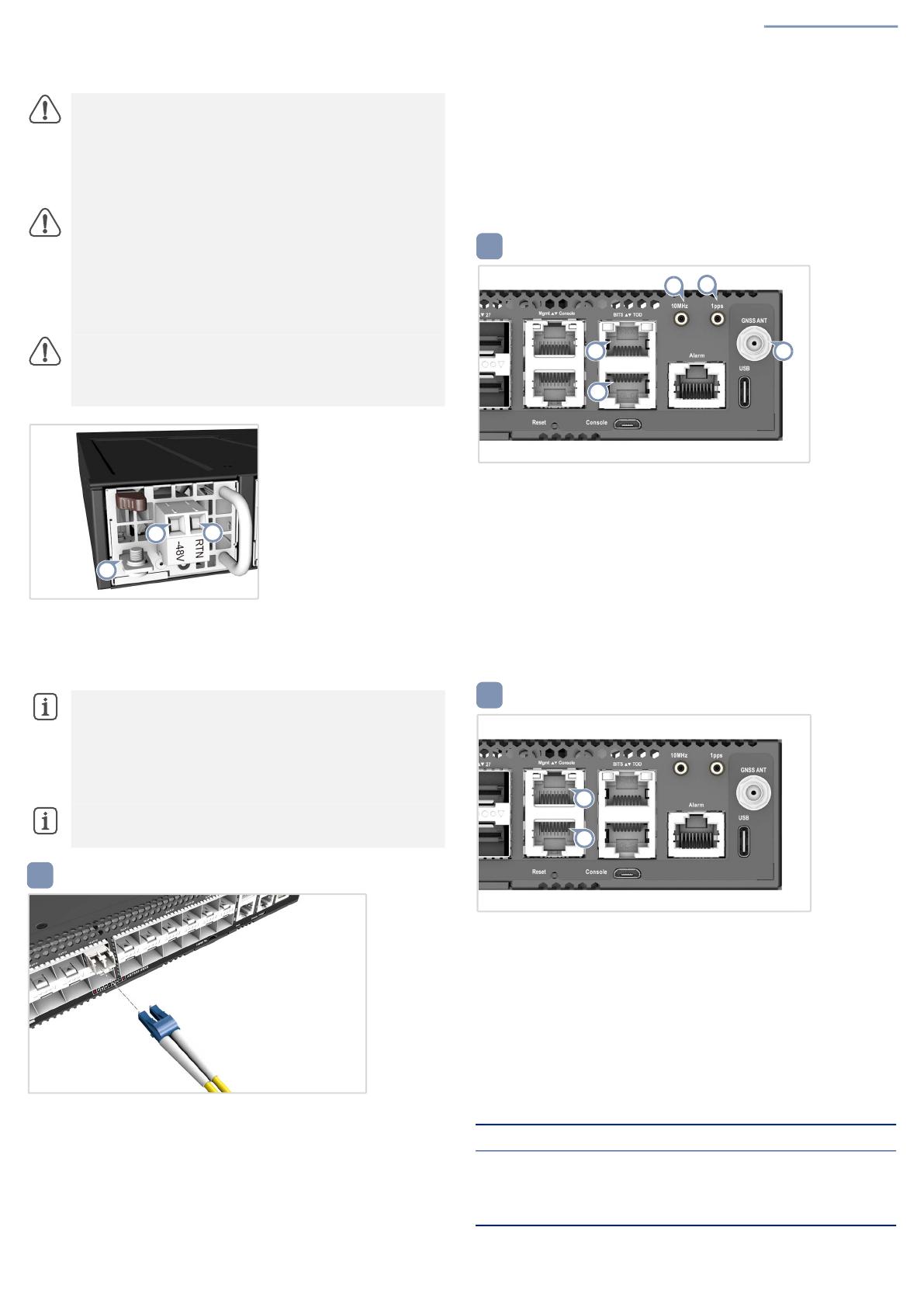
10MHz/1pps
Use coax cables to connect the 10 MHz and 1-pulse-per-second (1PPS)
ports to other synchronized devices.
GNSS Antenna
Attach an external antenna to the GNSS antenna port for clock
synchronization with GPS time.
Make Management Connections
Mgmt RJ-45 Port
Connect Category 5, 5e or better twisted-pair cable.
RJ-45 Console Port
Use an RJ-45-to-DB-9 null-modem console cable (not included) to
connect to a PC running terminal emulator software. Use a USB-to-male
DB-9 adapter cable (not included) for connections to PCs that do not
have a DB-9 serial port.
Configure the serial connection: 115200 bps, 8 characters, no parity,
one stop bit, 8 data bits, and no flow control.
Console cable pinouts and wiring:
Caution:
Before connecting power supply cables to the
device, ensure that power to the feed lines is turned off at the
supply circuit breaker or disconnected from the power bus.
Attention:
Avant de connecter les câbles d’alimentation à
l’appareil, assurez-vous que l’alimentation des lignes
d’alimentation est coupée au niveau du disjoncteur
d’alimentation ou déconnectée du bus d’alimentation.
Caution:
Use a UL/IEC/EN 60950-1 and/or 62368-1
certified power supply to connect to a DC converter, and a #14
AWG/1.5 mm2 (for -44 VDC to -60 VDC PSU) wire to connect
to a DC PSU.
Attention:
Utilisez une alimentation certifiée UL/IEC/EN
60950-1 et/ou 62368-1 pour le connecter à un convertisseur
CC et un câble AWG #14/1.5 mm2 (pour -44 VDC à -60 VDC)
pour vous connecter à une alimentation CC.
Caution:
All DC power connections should be performed by
a qualified professional.
Attention:
Toutes les connexions d’alimentation CC doivent
être effectuées par un professionnel qualifié.
Note:
It is suggested to use the following for DC power:
One UL 1015 AWG#10-14 stranded wire, 2m maximum
(-44VDC – -60VDC: Input+)
One UL 1015 AWG#10-14 stranded wire, 2m maximum (VDC
return: Input-)
One UL 1015 AWG#10-14 stranded wire, 2m maximum,
(green/yellow) green with yellow stripe (PE)
Note:
The DC terminal screws should be tightened to a
torque of 7 in-lbs maximum.
1
3
2
4
Device’s RJ-45 Console Null Modem PC’s 9-Pin DTE Port
6 RXD (receive data) <---------------- 3 TXD (transmit data)
3 TXD (transmit data) ----------------> 2 RXD (receive data)
4,5 SGND (signal ground) ------------------ 5 SGND (signal ground)
5
6


