Page is loading ...

Home » BEACON » BEACON VIPER 2 VP-F VIPER Floodlight Instructions
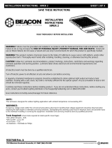
VIPER 2 VP-F VIPER Floodlight
Instructions
INSTALLATION INSTRUCTIONS – VIPER 2
SAVE THESE INSTRUCTIONS
INSTALLATION INSTRUCTIONS VIPER 2
READ THOROUGHLY BEFORE INSTALLATION
BEACON VIPER 2 VP-F VIPER Floodlight Instructions
Manuals+ — User Manuals Simplified.

Contents
1 VIPER 2 VP-F VIPER
Floodlight
2 Mast Arm Mount
3 Deco Knuckle Arm Mount
4 Knuckle Mount
5 Documents / Resources
5.1 References
6 Related Posts
VIPER 2 VP-F VIPER Floodlight
WARNING! Fixtures must be grounded and installed in accordance with the National Electrical Code and all local
codes.
Failure to do so may increase the RISK OF PERSONAL INJURY, PROPERTY DAMAGE, FIRE AND DEATH.
Install and use so fixture failures do not cause a hazard and use only in environments for which the product is
specifically marked.
WARNING! This product contains chemicals known to the State of California to cause cancer, birth defects,
and/or other reproductive harm. Thoroughly wash hands after installing, handling, cleaning, or otherwise touching
this product.
CAUTION! Follow ALL luminaire recommendations, product markings, instructions, restrictions and warnings
regarding luminaire operation and burning position. Luminaire label shows electrical and environmental
requirements and restrictions.
All electrical work must be done by a qualified electrician.
Turn off electric power to all affected circuits and allow to cool before servicing.
A regularly scheduled maintenance program should be established to retain optimum light output and reduce heat
retention. Dusting with a soft, clean, dry cloth is normally sufficient for the optical system. Any accumulation of
dust or dirt should be removed regularly.
Carefully read these instructions before installing product. If you do not understand these instructions, before
starting any work, contact your Hubbell Lighting distributor or techsupport@hubbell-ltg.com or (864) 678-1000
Give instructions to facility owner/manager for future reference.
NOTE:
This luminare is designed for outdoor lighting applications with ambient tempertures not exceeding 40°C
WARNINGS:
Dangerous voltage exists within the unit and all precautions observed in handling high voltage equipment should
be observed when replacing the light engine or otherwise servicing luminares. Disregarding this warning could
result in electrical shock and possible injury to the individual installing or servicing this equipment. Installation and
servicing should be done by qualified personnel.
Tools Required: (check tools required to install specific mount type)
Hex (Allen) Wrench – 3/16
Hex Socket – 1/2 & 3/4
Torx Driver – T-20
Screwdriver – Flat Blade & Phillips
INSTALLATION INSTRUCTIONS – VIPER 2
SAVE THESE INSTRUCTIONSArm Mount
Fixture Installation:
1. Open the driver compartment door (F) by removing (4) 8-32 T-20 Torx fasteners.
2. Remove pole cap (not shown) and position nut plate (B) inside pole (A) at pre-drilled hole locations.
3. Insert 5/16-18 threaded rod (C) through the arm and fasten on the interior of the housing with a 5/16-18 nut,
washer, and lockwasher.

4. Insert the opposite end of the threaded rod into the top hole of the pole drill pattern and thread into the top hole
of the nut plate (B). Torque nut (D) to 10 ft-lbs.
5. Route fixture wire from the arm through the wireway hole into the interior of the pole, and then out the top of the
pole.
6. Insert 5/16-18 hex bolt, washer, and lockwasher set (E) through the center hole located in the bottom surface
of the arm, through the lower hole of the pole drill pattern and into the nut block (B) and tighten to 10 ft-lbs.
7. Reinstall (if removed) the driver compartment door (F), close and secure (4) 8-32 fasteners.
8. Make power connections at the top of the pole and replace pole cap.
9. Ensure power is supplied to LEDs.
Mast Arm Mount
Fixture Installation:
1. Make power connections from the fixture wiring to the power feed wires. Route connected wiring into the pole
mast arm and pole interior.
2. Attach fixture by sliding the mast arm fitter over the pole mast arm (H). Ensure wiring is not pinched between

the Mast Arm Fitter and the pole mast arm.
3. Secure housing to arm by tightening (4) 3/8-16 set screws (G) using a 3/16 Allen Wrench. Torque to 12 ft-lbs.
4. Ensure power is supplied to LEDs.
NOTES:
POWER IN FROM POLE
For replacement LED Assemblies and Drivers please contact Hubbell Lighting for any replacement parts.
Contact your local distributor or agent to confirm parts availability prior to ordering replacement parts.
93157448 Rev. A
701 Millennium Boulevard Greenville, SC 29607 (864) 678-1000
Deco Knuckle Arm Mount
Fixture Installation:
1. Take bottom cover (K) off of deco knuckle arm using T-20 screwdriver to remove #8-32 screw.
2. Attach the deco knuckle to pole (L) by position sliding nut block (I) inside the pole at pre-drilled hole locations
and fastening the arm to the pole using the 1/2-13 bolts (J). Finger tighten first, then tighten fully to 50 ft-lbs.
Aim Adjustment:
Determine the desired vertical aim angle before attempting adjustments.
Notice that there are tick marks are at 15° intervals, plus long tick marks at 0°, 45° and 90°. The knuckle will
actually allow finer adjustments to 4° per step.
Remove the center hub cover (H)
Notice the large 1/2-13 hex head bolt in the center of the hub acts as a pivot and should be loosened slightly for

adjustment, but never removed.
CAUTION: secure housing assembly or obtain help holding and positioning the fixture while adjusting the aim.
Aim the fixture to the desired angle.
Once the aim angle has been completed, tighten the 1/2-13 Hex Head pivot bolt to 35 ft-lbs.
Replace the Knuckle cover (H).
Deco Arm Mount
Fixture Installation:
1. Take bottom cover (K) off of deco knuckle arm using T-20 screwdriver to remove #8-32 screw.
2. Attach the deco knuckle to pole (L) by position sliding nut block (I) inside the pole at pre-drilled hole locations
and fastening the arm to the pole using the 1/2-13 bolts
(J). Finger tighten first, then tighten fully to 50 ft-lbs.

NOTES:
For replacement LED Assemblies and Drivers please contact Hubbell Lighting for any replacement parts.
Contact your local distributor or agent to confirm parts availability prior to ordering replacement parts.
Knuckle Mount
Fixture Installation:
1. Make power connections from the fixture wiring to the power feed wires. Route the connected wiring into the
interior of the pole through the tenon.
2. Attach the Knuckle to pole (E) by sliding the Knuckle onto the tenon. Tighten each of the (8) 3/8-16 set screws
(G) using a 3/16 Allen wrench to approximately 12 ft-lbs.

Aim Adjustment:
1. Determine the desired vertical aim angle before attempting adjustments.
2. Notice that there are tick marks are at 15° intervals, plus long tick marks at 0°, 45° and 90°. The knuckle will
actually allow finer adjustments to 4° per step.
Remove the center hub cover (H)
Notice the large 1/2-13 hex head bolt in the center of the hub acts as a pivot and should be loosened slightly for
adjustment, but never removed.
CAUTION: secure housing assembly or obtain help holding and positioning the fixture while adjusting the aim.
3. Aim the fixture to the desired angle.
4. Once the aim angle has been completed, tighten the 1/2-13 Hex Head pivot bolt to 35 ft-lbs.
5. Replace the Knuckle cover (H).
Photocontrol Orientation
NOTE: A photocontrol is not included with this fixture.
This orientation procedure is only necessary if adjustment is required to aim the photocontrol in a certain
direction. Otherwise, the photocontrol will function properly with no adjustment required to the photcontrol
receptacle.
Angle Adjustment:
1. Remove shorting cap or photocontrol if installed.
2. Slightly loosen the two screws to allow rotation of the center section of the receptacle.
3. Insert a screwdriver tip into the adjustment slot located in the center of the the receptacle and rotate so that the

arrow indicator points in the desired direction (usually
north)
4. Sufficiently tighten two screws.
5. Install photocontrol into receptacle, twist and lock into position. Check to ensure photocontrol is pointing in the
desired direction.
NOTES:
For replacement LED Assemblies and Drivers please contact Hubbell Lighting for any replacement parts.
Contact your local distributor or agent to confirm parts availability prior to ordering replacement parts.
93157448 Rev. A
701 Millennium Boulevard Greenville, SC 29607 (864) 678-1000
www.beaconproducts.com
Documents / Resources

/