Page is loading ...

Manual
Electronic
Heat Cost Allocator
Sontex 565
Sontex 566 Radio
Sontex 868 Radio

0565P202 Installation guide line EHCA 565-566-868 24-10-2016 2
1. Specification
1.1 General Description
1.1.1 Type
The electronic heat cost allocators Sontex 565 / 566 / 868 operate either according to the single
sensor principle with start sensor or the double sensor principle. The device has been developed
and approved in accordance with the European Standard EN 834:2013.
1.1.2 Design
The heat cost allocator consists of a microprocessor, a lithium battery, two temperature sensors, a
heat conducting aluminium back plate, a multi-functional display and a plastic housing.
The measuring circuit consists of the temperature sensors, the analogue-digital conversion, the
reference resistance for standardising the measuring transformation and the microprocessor for
accessing the radiator heat output. During each measuring the circuit tolerances are eliminated
with a reference resistance and the heat cost allocator carries out an automatic self-test.
LC-Display
Optical Interface
Push Button
Seal
Standard aluminium back plate
for nearly all existing bolts with
common dimensions and mount-
ing possibilities – thus easy instal-
lation
Snap-on blind to cover colour
shadows for increased aesthetics
1.1.3 Characteristics
Measuring by two temperature sensors, radiator and ambient temperature sensor (NTC-
resistor).
Optional measuring principle: 1 sensor mode with start sensor or two sensor mode.
Unit scale or product scale.
Recording of cumulated heat consumption on the annual set day.
Recording of 144 monthly values and 18 half monthly values for cumulated heat consump-
tion.
Recording of 18 monthly values for the maximum radiator temperature.
Optical interface for the readout of the data and programming

0565P202 Installation guide line EHCA 565-566-868 24-10-2016 3
For heat cost allocator Sontex 566 Radio, the Sontex radio system (Supercom) is a bidi-
rectional system. Reading and programmable by radio.
For heat cost allocator Sontex 868 Radio, the radio module comprises a unidirectional ra-
dio transmitter.
Two telegrams: short telegram, OMS compliant and long telegram for Walk-by reading.
User-friendly operation by push button.
6-digit and high-contrast LCD display.
Automatic commissioning during the mounting on the aluminium back plate (available when
ordering).
Check code for postcard mail-in method
Possibility to connect a remote sensor on each version of heat cost allocator. The remote
sensor will be automatically detected by the heat cost allocator.
Remote sensor version with 2 m cable.
Standard aluminium back plate for nearly all existing bolts with common dimensions and in-
stallation possibilities – thus easy installation (no cutting and welding of bolts necessary).
Snap-on blind to cover colour shadows for increased aesthetics.
Safe operation and fraud/manipulation detection.
Lithium battery with a capacity of up to 10+1 year.
Meets EN 834:2013.
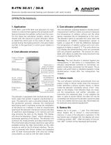
1.1.4 Display
The heat cost allocator has a LCD-display with 6 large main digits on the right and 2 smaller digits
on the left as well as two special symbols and one communication indicator. The main digits are
separated by four decimal points. Below, please find the display segments:
Normally, the heat cost allocators 565 / 566 / 868 are supplied with switched-off LCD-display. On
request, the heat cost allocators can also be supplied with permanent LCD- display.
1.1.5 Electronics
The device has an electrical circuitry with an 8-Bit-CMOS-micro controller of the latest generation
STM8L with extremely low current consumption operating at a voltage as from 1.8 V.
The temperature measuring circuit with automatic self-calibration measures the discharging time of
a capacitor. The accuracy of the measuring circuit is independent of the supply voltage.
1.1.6 Versions
Sontex 565 Standard:
Heat cost allocator Sontex 565 with optical interface, standard device.
Heat cost allocator Sontex 565 X with optical interface, standard device to substitute Kundo
201 / 202 devices.
Sontex 566 Radio (433.82 MHz):
Heat cost allocator Sontex 566 with optical interface, standard device.
Heat cost allocator Sontex 566 X with optical interface, standard device to substitute Kundo
201 / 202 devices.
Sontex 868 Radio wM-Bus (868.95 MHz):
Heat cost allocator Sontex 868 with optical interface, standard device.
Display with all active segments
88
888888

0565P202 Installation guide line EHCA 565-566-868 24-10-2016 4
Heat cost allocator Sontex 868 X with optical interface, standard device to substitute Kundo
201 / 202 devices.
For each version of heat cost allocator, it is possible to plug the connector of the remote sensor to
an interface inside the heat cost allocator. Refer to chapter 2.3 Mounting the Remote Sensor.
Once equipped with a remote sensor, the heat cost allocator will only work for an application with
remote sensor.
Remote sensor version with 2 m cable.
1.1.7 Optical Interface
With a standardised optical probe the consumption and configuration values can be transferred
directly to a computer. With the radio heat cost allocator 566 / 868 all consumption values can thus
be readout over the optical interface and over radio. The data are transmitted in M-bus-format acc.
to EN136757-3. Authorised personnel can alter the configuration of the device over the optical in-
terface with an optical probe.
1.1.8 Radio Transmission
The radio heat cost allocator 566 features a transceiver circuit in the 433 MHz band with integrated
antenna.
With the Sontex radio system, proven since more than 15 years; it is possible to readout the con-
sumption values via a mobile radio modem or via a radio central installed directly in the office.
The Sontex radio system is a bidirectional system, i.e. the radio heat cost allocator is only called
from a mobile PDA or a radio central upon request to send its data.
It is a great advantage that this system allows the alteration of the parameters over radio.
Please refer to chapter 1.7.3 Operation Mode for Radio Supercom (Sontex 566 Radio)
for the radio reading range.
1.1.9 Radio Transmission wM-Bus
The radio heat cost allocator 868 features a transmitter circuit in the 868 MHz band with integrated
antenna.
This radio module comprises a unidirectional radio transmitter which is used to transfer data ac-
cording to the wM-Bus (EN 13757-4) radio communication protocol and in compliance with the
OMS (Open Metering System) Release V3.0.1.
Please refer to chapter 1.7.4 Operation Mode for Radio wM-Bus (Sontex 868 Radio) for
the radio reading range.

0565P202 Installation guide line EHCA 565-566-868 24-10-2016 5
1.2 Operating mode
1.2.1 Cycle Time
The heat cost allocators 565 / 566 / 868 operate in a cycle of 4 minutes.
Most of the time, the device is in sleeping mode. Every 4 minutes the
device is set into operation and operates according to the adjoining dia-
gram.
The clock-pulse generator is a counter which is completely independent
from the rest of the program. This counter is designed in a way so that it
is impossible to stall the cycle or to skip one or more cycles.
Each cycle follows the adjoining diagram. The measuring and calculating
processes are explained in detail later.
The tasks carried out during one cycle are taking approx. 100 ms. This
means that the device is in sleeping mode more than 99.8 % of the time.
It can be set into operation between two cycles over the optical probe or
by pushing the button. In this case it carries out the requested task and
then returns to sleeping mode.
In case an optical probe is connected or the button is pushed during the
course of the cycle, the respective value is readout at the end of the cy-
cle.
The button can be pushed for an indefinite period of time and the optical
probe can be left in its position since the normal function of the device is
not impaired by an influence from outside.
1.2.2 Single Sensor Version with Start Sensor
The start sensor of the single sensor version serves as an ambient temperature sensor which
mainly functions during the heating up period.
The start temperature is the threshold temperature of the radiator at which the device always starts
to carry out energy ratings. For these ratings, the measured radiator temperature and an assumed
ambient temperature of 20° C are used as calculation basis.
1.2.3 Double Sensor Version
For the double sensor version basically the same specifications apply as for the single sensor ver-
sion with start sensor. However, for calculating the room temperature the real temperature, meas-
ured by the ambient temperature sensor (corrected via the corresponding radiator-dependent „K
air
-
value“), is used as the basis.
1.2.3.1 Heat Accumulation Mode
In order to avoid faulty measuring due to heat accumulation (e.g. in case the radiator is hidden by
panels), the device switches from a defined ambient temperature (e.g. 28°C) to the one sensor
mode and calculates with an ambient temperature of 20° C.
Start of cylce
Measuring and
calculation of the
temperature
Calculation of the
new consumption
value
Update time and
date
End of cycle
Update display

0565P202 Installation guide line EHCA 565-566-868 24-10-2016 6
1.2.4 Comparison of the Measuring Principles
Single sensor device with start sensor
measuring principle
For heating systems with tm
min
≥ 55 °C
The heat cost allocator calculates with a set ref-
erence temperature of 20 °C
Application:
Single sensor devices with start sensor are used
in areas where normal ambient temperatures
are given. For low temperature heating systems
the double sensor device is recommended.
For radiators which are covered or blocked by
fixtures, normally the single sensor devices are
used because the double sensor device is not in
a position to capture the current ambient tem-
perature due to the heat accumulation.
Double sensor measuring principle
For heating systems with tm
min
≥ 35 °C
The heat cost allocator calculates with a vari-
able reference temperature T
air temperature
Application:
Double sensor devices are used in areas
where precise measuring of the ambient tem-
perature is necessary and/or in low tempera-
ture heating systems.
Radiators which are covered or blocked by
fixtures are detected automatically by the
double sensor system which then switches
over internally to the single sensor mode.
Within one billing unit, only one measuring principle (either single sensor measuring principle with
start sensor or double sensor measuring principle) can be used. Mixed fitments or the use of dif-
ferent types of devices in the same billing unit is therefore also not allowed.
The processes for determining the K-value for the single sensor device with start sensor and the
double sensor device are identical. It is only the measuring principle that is different.
1.2.5 Temperature Measurement and Calculation
The temperature is measured with an NTC – resistor. For the resistance measurement the dis-
charging time of the capacitor is measured. The measurement is carried out as follows:
1.2.5.1 Measuring of a Resistor, Principle
1. Charging of the capacitor
2. Discharging of the capacitor through the resistance which is to be measured. At the same
time a 16+1 bit-timer starts with the discharge to measure the discharging time
3. As soon as the voltage on the capacitor terminals reaches a certain value, an interrupt is
induced and the timer stops. At the same time the discharging of the capacitor is stopped
as well.
After the three mentioned stages, the timer provides a 16-bit-value which corresponds to the dis-
charging time of the capacitor through the resistance which is to be measured. In case the re-
sistance is known (reference resistance), the constant ratio between discharging time and re-
sistance can be assessed.
1.2.5.2 Calculation of the Value of an Unknown Resistance (e.g. sensor resistance)
The capacitor C is loaded at constant current. The interrupt at the end of the discharge is triggered
by the same threshold voltage (a fraction of the discharge voltage). If these two conditions are met,
the discharge time is directly proportional to the resistance. With a reference resistance R
ref
whose

0565P202 Installation guide line EHCA 565-566-868 24-10-2016 7
exact value is known, it is now possible to calculate the unknown resistance value R
x
with the fol-
lowing equation:
t
R
t
R
R
t
t
R
ref
ref
X
X
X
X
ref
ref
= ⇒
= ⋅
From this equation the self-calibration of the converter can be derived, which is given by measuring
the discharging time through the reference resistance.
1.2.5.3 Measuring of the Radiator and Ambient Temperature
The following measurements are carried out during one cycle:
1. Measuring of the reference resistance R
ref
2. Measuring of the ambient temperature sensor NTC
A
3. Measuring of the radiator temperature sensor NTC
R
The measuring values are calculated with the following formula:
NTC
t
t
R TC
t
t
R
A
NTC
ref
ref R
NTC
ref
ref
A R
= ⋅ = ⋅
N
The reference resistance value is defined ex works with a tolerance of 0.5% with 50 ppm. The ref-
erence resistance features an excellent temperature and long-term stability.
The capacitor value and the threshold voltage have to remain stable over the whole cycle. Howev-
er, they can vary at the medium- or long term without causing any failures because the self-
calibration of the converter is repeated in every cycle while measuring the reference resistance.

0565P202 Installation guide line EHCA 565-566-868 24-10-2016 8
1.2.6 Calculation of the Displayed Consumption Value
The value displayed on the heat cost allocator is calculated as follows:
Single sensor device Double sensor device
∫
−
=
dt
T
KqKc
Q
H
33
.
1
60
20
*
∫
−
= dt
TT
KqKcQ
AH
33.1
60
*
Explanation: T
H
Temperature of the radiator surface in [°C]
T
A
Ambient temperature in [°C]
Q Displayed consumption value, without unit
Kc Factor that carries back the ΔT measured at a normalized value
Kq Factor Kq is a numerical value of the nominal power of the radiator
stated in [KW]
Unit scale: Kc = 1 and Kq = 1
Product scale: Kc <> 1 and Kq <> 1
1.2.7 Start of Counting
The updating (increment) of the consumption value is carried out under the following conditions:
During winter period (heating period):
(T
R
≥ 25 °C)
Or
(T
R
≥ 20 °C) AND (T
R
- T
A
≥ T
MIN
)
During summer period (off heating period):
(T
R
≥ 35 °C)
Or
(T
R
≥ 20 °C) AND (T
R
- T
A
≥ T
MIN
)
Explanation: T
R
Radiator temperature
T
A
Ambient temperature
T
MIN
Minimum temperature difference between radiator and room
3K for standard device (winter heating period standard setting)
4K for remote sensor device (summer heating period standard setting)
Note:
The thresholds of starting (25°C et 35°C) are indicative values. These temperatures of starting are
adjusted according to the needs and specificities of the customer.

0565P202 Installation guide line EHCA 565-566-868 24-10-2016 9
1.3 Display and Additional Functions
1.3.1 The Menu Sequences of the Digital Display
The menu sequences
Ex factory all menu sequences are activated. With the
software Prog6 the order of the menu sequences 1 - 15
can be changed in any order. However the order within the
individual menu sequences 1 – 15 cannot be changed. It is
also possible to hide individual menu sequences so that
they are not visible to the end-user.
When reading out over the optical interface or via radio the
complete set of data is always readout and transferred.
Operation of the Push Button
When pushing the button briefly the digital display always
goes to the next menu sequence.
When pushing the button in one menu sequence for 2
seconds the individual values within the selected menu
sequence can be accessed. When the last value within
one menu sequence has been displayed, the 1
st
position
will be displayed by pushing the button again.
If the button is not pushed for 2 minutes, the digital display
returns to the cumulated consumption value.
LC-Display
Optical Interface
Push Button
Seal
Display position
1
Long key press
36 Monthly Values
Consumption value
Current time
Current date
Short key press
Set Day value
Radiator temperature
Short key press
Short key press
Short key press
Display position 2
Display position 3
Display position 4
Display position 5

0565P202 Installation guide line EHCA 565-566-868 24-10-2016 10
1.3.2 The Digital Displays
During normal operation the display is deactivated and can be activated by pushing the button.
If the button is not pushed, the display will be active for 2 minutes only.
On request, the heat cost allocator is also available with permanent display 24h/24h or with a roll-
ing menu displayed.
Consumption Value Unit Scale
Consumption Value Product
Scale
On the display of the heat cost allocator with unit scale an
index u for unit is shown on the left side. If the index u is not
displayed, the heat cost allocator is equipped with the prod-
uct scale.
When commissioning the device this value is 000000. When
reaching the value 999999, the counting restarts automati-
cally at 000000.
Display in Euro
.
The heat cost allocators 6556/566/868 have the option to
display the heating cost in Euro.
The cost in Euro indicated on the display is only approxi-
mate and is based on historical values from the previous
year.
The displayed cost does not necessarily represent the
charges to be paid.
Manufacturer and supplier decline any claims concern-
ing the use and interpretation of the indicated values.
This option can be activated via the software Prog6.
Set day Value
With the index Sd the consumption value recorded at mid-
night of the set day is displayed.
The consumption value recorded can be in unit scale or in
product scale. It’s depending of the unit setting.
If a new device has not yet reached the programmed set
day, 000000 is displayed.
Check code
With the index CC the check code for the plausibility check
of the manual readout is displayed.

0565P202 Installation guide line EHCA 565-566-868 24-10-2016 11
Time
The current time (always winter time).
Date
..
The current date of the heat cost allocator.
Set Day
..--
It is possible to program an annual set day on which the
cumulated consumption value as well as the maximal radia-
tor temperature are recorded.
With the index Sd the programmed annual set day is dis-
played.
Date of Opening of the Device
..
Each heat cost allocator is equipped with a manipulation
protection which detects an unauthorised opening of the
device after installation to the radiator. The date of the last
opening of the device is recorded and displayed with the
index od.
Commissioning Date
..
With the index Cd the commissioning date is displayed, i.e.
the date on which the device has been activated by pushing
the button or during the mounting of the aluminium back
plate if the function automatic commissioning is set.
Cumulated Duration of the
Opening of the Device
With the index du, the cumulated duration in minutes during
which the device was opened is detected. This display turns
up only after commissioning in case the heat cost allocator
was opened or removed.
Fraud Counter
This value indicates how many times the fraud / manipula-
tion was activated.
Identification Number
With the index an 8 digit identification number is dis-
played. Ex factory the serial number is identical with the
identification number. The first two digits of the identification
number are the two small digits on the left upper side of the
digital display.
Running Hours
With the index rh, the running hours is displayed. This value
can be compared to the battery use duration.

0565P202 Installation guide line EHCA 565-566-868 24-10-2016 12
Monthly Values
The cumulated consumption values are recorded automati-
cally at midnight on the last day of each month.
Number of monthly values: 36
The small digits on the upper left side show the number of
previous monthly values. Digit 01 stands for the recent full
month and digit 36 stands for the least recent month. All
monthly values are set to 000000 when the device is com-
missioned.
Note 566 radio :
The radio heat cost allocator 566 only transmits the first
18 monthly values via radio telegram.
Note 868 radio :
Short telegram, OMS compliant: no monthly values
transmitted via radio telegram.
Long telegram for Walk-by reading, the first 18 monthly
values transmitted via radio telegram.
Half Monthly Values
The cumulated consumption values are recorded automati-
cally at midnight on the 16th of each month.
Number of monthly values: 18
The small digits on the upper left side indicate the number
of half monthly values. Digit 41 stands for the recent half
monthly value and digit 58 for the least recent half monthly
value. All half monthly values are set to 000000 when the
device is commissioned.
Note 566 radio :
No half monthly values transmitted via radio telegram.
Note 868 radio :
Short telegram, OMS compliant and long telegram for
Walk-by reading: no half monthly values transmitted via
radio telegram.
Radiator Temperature
.
With the index
tr the current radiator temperature is dis-
played.
Ambiant Temperature
.
With the index
tA the current ambient temperature is dis-
played.

0565P202 Installation guide line EHCA 565-566-868 24-10-2016 13
Maximum Radiator Tempera-
ture of the Current Heating Pe-
riod
.
With the index Π
the maximum radiator temperature of the
current heating period (since the Set Day) is displayed.
Maximum Radiator Tempera-
ture of the Previous Heating
Period
.
With the index
Sd the maximum radiator temperature of the
previous heating period (before the Set Day) is displayed.
Monthly Value for Maximum
Radiator Temperature
.
.
.
With the index
ΠΠ the maximum radiator temperature of the
currently month is displayed.
Number of monthly values: 18
Recording of 18 monthly values for the maximum radiator
temperature.
The small digits on the upper left side show the number of
previous monthly values. Digit 01 stands for the recent full
month and digit 18 stands for the least recent month.
All monthly values are set to 000000 when the device is
commissioned.
Software Version
...
On the right side the software version x.x.x of the heat cost
allocator is displayed.
Measuring Principle
The index -- or FF indicates the type of the radiator sensor:
-- = Standard device, compact sensor.
FF = Remote sensor device, remote sensor.
1 SENS = single sensor device with start sensor.
2 SENS = double sensor device.
Segment Test
Segment test of the display.
Error Message
.
If an error is detected,
Err is displayed in the first display
sequence with the corresponding error message.
wM-Bus mode
Telegram defined into heat cost allocator.
Type of telegram must be defined when ordering.
Short telegram (Short ) used.
Long telegram (LonG) used.

0565P202 Installation guide line EHCA 565-566-868 24-10-2016 14
1.3.3 Rolling Digital Display
The EHCA 565, 566 and 868 also feature the possibility of a rolling display 24h/24h.
With the software Prog6 or Sontex916/ Tools916 or Tools Supercom, it is possible to individual-
ize the rolling display.
Up to 15 parameters can be chosen optionally from the list below. These parameters can be com-
bined in any order and are then shown on the rolling display.
Consumption value.
Time.
Date.
Set Day.
Set Day value.
36 monthly values for cumulated consumption.
18 half monthly values for cumulated consumption.
Radiator temperature.
Ambient temperature.
Identification number.
Maximum radiator temperature of the previous heating period.
Maximum radiator temperature of the current heating period.
18 monthly values for the maximum radiator temperature.
Error code.
Manipulation protection: storing of the duration of the last manipulation with date and the
accumulated duration of all manipulations in minutes.
Fraud Counter.
Segment test.
Software version.
Running hours.
Commissioning date.
Measuring principle, single sensor device with start sensor or double sensor device.
Short or long telegram for radio wM-Bus.
The duration of the display of the values can be chosen individually between 1 - 30 seconds.
Example:
Order and duration of display
Pos. 0 : Error (parameter ex factory, cannot be changed) [5 s]
(only displayed in case of an error message)
Pos 1 : Time [1 s]
Pos 2 : Segment test [5 s]
Pos 3 : Consumption value [10 s]
Pos 4 : Set Day [1 s]
Pos 5 : Set Day value [8 s]
Pos 6 : Monthly value [5 s]
Pos 7 : Blank (therefore no display).
Pos 8 – Pos 15 : Blank (therefore no display. It is not necessary to occupy all positions).
The rolling display can also be deactivated by the Prog6, i.e. the device operates as in standard
menu mode except that only these values and the values of the corresponding sub-menus that
have been defined in the rolling menu can be displayed by pushing the button. After 2 minutes dur-
ing which the button has not been pushed, the display goes out.

0565P202 Installation guide line EHCA 565-566-868 24-10-2016 15
1.3.4 Communication Indicator and Measuring Indicator ●
The communication indicator displays if the heat cost allocator is currently making a calculation
and/or if it communicates internally or externally over the optical or wireless interface (only radio
Supercom).
If the arrow of the communication indicator points inwardly
internal communication takes place over the optical or wire-
less interface (only radio Supercom).
If the arrow of the communication indicator points outwards
external communication takes place over the optical or wire-
less interface (only radio Supercom).
If the frame of the communication indicator appears the heat
cost allocator has detected a wake-up signal (optical or ra-
dio Supercom)
If the point indicator appears the heat cost allocator is carry-
ing out a measuring or a calculation.
1.3.5 Real Time Clock and Calendar
The device has a 24 h real time clock and a calendar. However, the change from summer to winter
time is not taken into account. The calendar is programmed until December 31 2099, including all
leap years. The real time clock as well as the date of the heat cost allocator can be readout over
the optical interface or via radio and if necessary be updated.
If the current date and time have to be updated over the optical interface or via radio, it is
necessary to check the date of the computer first. Date and time of the device aim at those
of the computer. If the reading/programming device (computer/PDA/ Smart Phone) has a
wrong time, this time will be programmed into the heat cost allocator and suddenly no
longer be reached at the usual time, because the time of the heat cost allocator possibly is
shifted by several hours.

0565P202 Installation guide line EHCA 565-566-868 24-10-2016 16
1.3.6 Readout
The current and monthly values recorded by the heat cost allocator 565 / 566 / 868 as well as sev-
eral other parameters can be readout over the optical interface or also over radio.
The following parameters are transmitted:
Optical Interface:
Sontex 566 Radio Supercom :
Identification number (information in
header).
Date and time.
Consumption value.
Set Day.
Set Day value.
Maximum radiator temperature of previ-
ous heating period.
36 monthly values and 18 half monthly
values for cumulated consumption.
18 monthly values for the maximum ra-
diator temperature.
Rating factor K
C
.
Rating factor K
Q
.
Current radiator temperature.
Current ambient temperature.
Maximum radiator temperature of the
current heating period.
Manipulation protection:
- Duration of the manipulations.
- Date of the last manipulation.
- Manipulation counter.
Error code.
Firmware version.
Commissioning date.
State of parameters.
36 half monthly values for the average
ambient temperature.
Identification number (information in
header).
Date and time.
Consumption value.
Set Day.
Set Day value.
Maximum radiator temperature of previ-
ous heating period.
18 monthly values for cumulated con-
sumption.
Rating factor K
C
.
Rating factor K
Q
.
Current radiator temperature.
Current ambient temperature.
Maximum radiator temperature of the
current heating period.
Manipulation protection:
- Duration of the manipulations.
- Date of the last manipulation.
- Manipulation counter.
Error code.
Firmware version.
Commissioning date.
State of parameters.
36 half monthly values for the average
ambient temperature.
Cost per unit totalized.
Parameter for Auto-reset totalizer.
Statistics counters for Radio.

0565P202 Installation guide line EHCA 565-566-868 24-10-2016 17
The following parameters are transmitted by Sontex 868 Radio wM-Bus:
Short telegram, OMS compliant :
Long telegram for Walk-by reading:
Identification number (information in
header).
Date and time.
Consumption value.
Set Day.
Set Day value.
Error code.
Current radiator temperature.
Current ambient temperature
State of parameters.
Identification number (information in
header).
Date and time.
Consumption value.
Set Day.
Set Day value.
18 monthly values for the cumulated
consumption.
Rating factor K
C
.
Rating factor K
Q
.
Current radiator temperature.
Current ambient temperature.
Maximum radiator temperature of the
current heating period.
Maximum radiator temperature of the
previous heating period.
Manipulation protection:
- Duration of the manipulations.
- Date of the last manipulation.
- Manipulation counter.
Error code.
Firmware version.
Commissioning date
State of parameters.
AES 128 bits encryption is available for all versions.
1.3.7 Check Code
A special additional feature of the electronic heat cost allocator 565 / 565 / 868 is the check code
function for the postcard mail-in method.
With especially developed algorithms a 5 digit check code is generated out of several device data.
With this check code the values stated on the postcards mailed-in by tenants can be cross
checked.
For this check, the following parameters are required:
Identification number.
The date.
The current consumption value.
The check code.
For the verification of the check code Sontex places all necessary tools (programs, formulas) at the
disposal of the authorized personnel.
1.3.8 Change of Battery
The battery of the heat cost allocator is soldered. The lithium battery is not rechargeable. A change
of battery is not planned. Therefore the heat cost allocators have to be replaced after 10 years.

0565P202 Installation guide line EHCA 565-566-868 24-10-2016 18
Disposal
It is mandatory to dispose of the heat cost allocator environmentally friendly or to return it after use
to the manufacturer for appropriate disposal to ensure that the components are recycled in accord-
ance with the battery and electronic scrap regulations. Should you do the disposal yourself please
get information from your local authority on the recycling possibilities
1.3.9 Protection against Outside Influences
1.3.9.1 Seal
The heat cost allocator is closed with a seal which cannot be removed without damaging it. Thus it
is impossible to open the device unnoticed.
After installation, the electronic part of the device is no longer accessible. The digital display, the
push button and the optical interface are covered by a sight glass. It is impossible to access the
inside of the device through these openings without damaging the sight glass.
1.3.9.2 Electronic Detector in Case of an Opening of the Device
The electronic detector detects unauthorised opening, removing and closing of the heat cost allo-
cator. As soon as the housing of the heat cost allocator is opened and/or removed, the electronic
detector triggers an error message. The duration of each opening is counted, cumulated and only
the last date of opening recorded.
1.4 Special Functions
1.4.1 Suppression of Summer Counting
The period during which summer counting is suppressed can be programmed by the software.
If the heat cost allocator is in the period of summer counting suppression, consumption measuring
is deactivated. If an automatic readout is carried out during this period the temperatures can be
read anyway since the temperature measuring is still active.
1.4.2 Annual Reset of the Consumption Value
The function of the annual reset of the cumulated consumption value can be programmed by the
software over the optical interface. One of the following options can be chosen for the reset:
Set Day
Never
Please note that only the cumulated consumption value is reset. All other values are not reset.

0565P202 Installation guide line EHCA 565-566-868 24-10-2016 19
1.4.3 Unit Scale and Product Scale
For the heat cost allocators Sontex 565 / 566 / 868, distinction is made between the unit scale and
the product scale.
If heat cost allocators are used with the same scale on all radiators, this scale is called unit scale.
The display values are the same on the different radiators if the heat cost allocators are exposed to
the same temperature for the same period of time.
The evaluation of the display values is carried out arithmetically with the rating factors of the calcu-
lation software to receive the final consumption values.
1.4.3.1 Advantages of the Unit Scale
Easy and quick installation of the heat cost allocator, no programming necessary.
Possible errors by doing the scaling on site are avoided due to allocation by experts.
With the product scale, the radiator rating data are programmed in the heat cost allocator on site.
The overall rating factor total (K
Total
) is calculated directly in the heat cost allocator and thus the
consumption value is displayed immediately.
1.4.3.2 Advantages of the Product Scale
The actual consumption of each consuming point within one billing unit can be compared
easily and quickly on site.
1.5 Parameterization
The software Prog6 allows the parameterization over the optical interface.
To protect heat cost allocator against fraud, a password has been integrated into the 565 / 566 /
868 products, therefore also in the software. The default ‘’installer’’ password ex-factory of the heat
cost allocator is ''00001234'', and may be changed by the user.
1.6 Error
The heat cost allocator displays an error message with the 3 letters “ Err. ” and a code. If several
errors occur at the same time, the different codes are added together.
The error is displayed in the first position of the display menu. It will still be possible to select all the
other display menus by pressing the navigation button. If the navigation button is no longer
pressed for a period of 2 minutes, the error code will automatically appear again in the first position
of a display menu.
Display of an error automatically disappears when the error is no longer present.
1.6.1 List of Errors
Err. 1 Manipulation (fraud).
Err. 2 Measuring error.
Err. 32 Push button constantly pushed.
Err. 64 Measured temperature not within temperature range (0...105°C ;
0...120°C remote sensor).

0565P202 Installation guide line EHCA 565-566-868 24-10-2016 20
1.7 Radio Standby – Radio-HCA 566 / 868
In order to achieve a user-friendly and power-saving radio standby, the radio heat cost allocator
features the following different operating modes:
Measure :
Optical :
Radio :
Sleeping
mode
Installation
mode
Operation
mode
Off
Off
Off
On
LCD
Display :
Measure :
Optical :
Radio:
566:
868:
On
On
On
24h/24h
30 s
On
Heat cost allocator removed from the
aluminium back plate.
LCD
Display :
Measure :
Optical :
Radio:
566:
868:
On
On
On
(**)
120 s
On
End of the
second
day at
midnight
Reset all
recorded
values
( SLEEP displayed *)
Point displayed
( )
LCD
Display :
* : SLEEP information will be displayed by pushing the push button.
**: See also in chapter 1.7.3 Operation Mode for Radio Supercom (Sontex 566 Radio)
1.7.1 Sleeping Mode
Ex factory the radio heat cost allocator is in sleeping mode, but the internal clock and the date are
running.
Current consumption is reduced to a minimum since no measuring and no calculations are carried
out. Only the optical communication interface is available.
Transition from sleeping to installation mode is achieved by pushing the button once the heat cost
allocator is mounted on the aluminium back plate or by an automatic commissioning during the
mounting on the aluminium back plate (must be specified when ordering).
1.7.2 Installation Mode
The ● symbol indicates that the heat cost allo-
cator is in installation mode.
During the installation mode all functions of the radio heat cost allocator 566 / 868 are carried out.
For heat cost allocator 566, the radio transmission is possible 24h/24h till at the end of the
second day at midnight. This guarantees an optimal availability of the radio heat cost allo-
cator for test purposes during installation.
Transition from sleeping mode to installation mode is achieved by two different ways:
1. Pushing the push button once the heat cost allocator is mounted on the aluminium
back plate.
2. An automatic detection during the mounting on the aluminium back plate. This func-
tion must be specified at the order.
/