
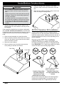
Installation Instructions
Epicure
®
and Millennia
™
Wall Mount Range Hoods
For use with models:
EH30, EH36, EH42, EH48, EH54,
MH30, MH36 and MH48
Part No. 102139 Rev. F
APPROVED FOR USE WITH ALL DACOR
®
RANGES AND COOKTOPS.
TESTED IN ACCORDANCE WITH THE LATEST EDITION OF ANSI/UL 507
STANDARD FOR ELECTRIC FANS AND CAN/CSA-C22.2 NO. 113 STANDARD
FOR FANS AND VENTILATORS.

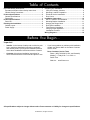
Installation Instructions .................................................... 9
Rotating the Blower ........................................................ 10
AHT10 Transition Kit Installation .................................... 16
Mounting Bracket Installation ......................................... 17
Hanging the Range Hood .............................................. 18
Duct Work Installation .................................................... 18
Final Electrical Installation ............................................. 19
Verifying Proper Operation ............................................. 21
Installation Checklist ...................................................... 21
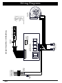
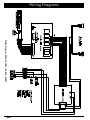
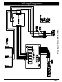
Wiring Diagrams .............................................................. 22
Table of Contents
Before You Begin...
Important Safety Instructions .......................................... 1
Important Information About Safety Instructions .............. 1
General Safety Precautions ............................................. 2
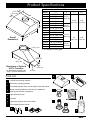
Product Specifications .................................................... 3
General Specifications ..................................................... 3
Dimensions ...................................................................... 4
Product Specifications ..................................................... 5
Parts List .......................................................................... 5
Planning the Installation ................................................... 6
Cabinet Layout ................................................................. 6
Power Supply ................................................................... 6
Preparing for Installation .................................................. 8
Verify the Package Contents ............................................ 8
Mounting Location Preparation ........................................ 8
Electrical Service Installation ........................................... 8
Duct Cutout ...................................................................... 8
All specifications subject to change without notice. Dacor
assumes no liability for changes to specifications.
Important:
Installer:• In the interest of safety and to minimize prob-
lems, read these installation instructions completely
and carefully before you begin the installation process.
Leave these installation instructions with the customer.
Customer:• Keep these installation instructions for
future reference and the local electrical inspector’s use.
If you have questions or problems with installation, •
contact your Dacor dealer or the Dacor Customer
Service Team.
Dacor Customer Service Team
Phone: (800) 793-0093 (U.S.A. and Canada)
Monday — Friday 6:00
a.m. to 5:00 p.m.
Pacific Time
Web site: www.Dacor.com
© 2008 Dacor, all rights reserved.

1
Important Information About
Safety Instructions
The • Important Safety Instructions and warnings in
these instructions are not meant to cover all possible
problems and conditions that can occur. Use common
sense and caution when installing, maintaining or oper-
ating this or any other appliance.
Always contact the Dacor Customer Service Team •
about problems and conditions that you don’t under-
stand.
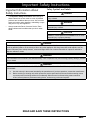
Important Safety Instructions
Safety Symbols and Labels
DANGER
Immediate hazards that WILL result in severe personal
injury or death.
WARNING
Hazards or unsafe practices that COULD result in severe
personal injury or death.
CAUTION
Hazards or unsafe practices that COULD result in minor
personal injury or property damage.
DANGER
To avoid the possibility of explosion or fire, do not store or use combustible, flammable or explosive vapors and liquids
(such as gasoline) inside or in the vicinity of this or any other appliance. Also keep items that could explode, such as
aerosol cans away from cooktop burners, ovens and range hoods. Do not store flammable or explosive materials in
adjacent cabinets or areas.
WARNING
If the information in this manual is not followed exactly, a fire or explosion may result causing property damage, personal
injury or death.
WARNING
WARNING - TO REDUCE THE RISK OF FIRE, ELECTRIC SHOCK, OR INJURY TO PERSONS, OBSERVE THE
FOLLOWING:
Use this unit only in the manner intended by the manufacturer. If you have questions, contact the manufacturer.a.
Before servicing or cleaning unit, switch power off at service panel and lock the service disconnecting means b.
to prevent power from being switched on accidentally. When the service disconnecting means cannot be
locked, securely fasten a prominent warning device, such as a tag, to the service panel.
READ AND SAVE THESE INSTRUCTIONS

2
Important Safety Instructions
Do not1. install or operate this hood if it has been damaged, dropped, has damaged electrical wires or is not working
properly. If the product is damaged when received, immediately contact the dealer or builder.
This range hood must be installed and grounded by a qualified installer according to these installation instructions. 2.
All installation work and electrical wiring must be performed in accordance with all applicable codes and standards,
including fire-rated construction. A minimum of two people are required to safely install this appliance.
Install or locate this appliance only in accordance with these installation instructions and the requirements specified 3.
by the manufacturer of the cooktop or range. Improper installation, adjustment, alteration, service or maintenance
can cause serious personal injury or property damage.
The customer should not install, repair or replace any part of the range hood unless specifically recommended in 4.
the literature accompanying it. A qualified service technician should perform all other service. Contact the nearest
Dacor authorized service representative at (800) 793-0093, or at www.Dacor.com for examination, repair or
adjustment.
Use this range hood only for its intended purpose as outlined in the use and care manual. Do not use this range 5.
hood to vent hazardous or explosive materials or vapors. This range hood is not intended for commercial use or for
use with a commercial range or cooktop.
Keep all packaging materials away from children. Plastic bags can cause suffocation.6.
Do not use an extension cord or adapter plug with this appliance.7.
Sufficient air is needed for proper combustion and exhausting of gases through the flue (chimney) of fuel burning 8.
equipment to prevent back drafting. Follow the heating equipment manufacturer’s guidelines and safety standards
such as those published by the National Fire Protection Association (NFPA), and the American Society for Heating,
Refrigeration and Air Conditioning Engineers (ASHRAE) and the local code authorities.
The installer must show the customer the location of the fuse box or circuit breaker panel box so that the customer 9.
knows where and how to turn the power off.
When cutting or drilling into the wall or ceiling, do not damage electrical wiring and other hidden utilities. 10.
Before installing or servicing the range hood, switch power off at the fuse box circuit breaker and lock the electrical 11.
panel door to prevent power from being switched on accidentally. When the electrical panel cannot be locked,
securely fasten a prominent warning device, such as a tag, to the electrical panel.
Read the use and care manual completely before using the appliance. Clean the appliance only as instructed in the 12.
use and care manual. Use only the cleaners specified.
Do not tamper with the controls.13.
Never allow the filter(s) to become blocked or clogged. Do not allow foreign objects, such as cigarettes or napkins, 14.
to be sucked into the hood.
Clean the filter(s) and all grease-laden surfaces often to prevent grease fires and maintain performance.15.
If the cooktop and range hood are near a window, use an appropriate window treatment. Avoid long drapes or 16.
other window coverings that could blow over the cooktop and hood, resulting in a fire hazard.
Always run the fan(s) whenever the cooktop is operating.17.
Never leave the range or cooktop unattended when a burner (or element) is in use. Boil-overs and greasy spills 18.
may smoke and/or ignite.
Do not leave children alone or unattended in the area where the cooktop and range hood are in use. Never allow 19.
children to sit or stand on an appliance. Do not let children play with a range, cooktop or range hood. Do not store
items of interest to children above or around the cooktop, range or range hood.
The minimum vertical distance between the cooktop surface and the exterior part of the hood must be no less 20.
than 25” (63.5 cm). The vertical distance may be longer for the range or cooktop being used. Consult the range or
cooktop installation instructions for the minimum and maximum vertical distance from the appliance being used.
WARNING
General Safety Precautions
To reduce the risk of fire, electric shock, serious injury or death when using your appliance, follow basic safety
precautions, including the following:

3
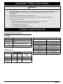
General Specifications
All Models
Fan Speeds 4
Filters Mesh type, dishwasher safe
Exhaust(s) 8-inch
Total Connect
Load
120 Vac, 60 Hz, 9 Amp. Max.
(10.0 Amp Max. surge)
Lights 120 Vac, 75 W halogen
Model Specific
Model Number
EH48, MH48
EH54
EH42
EH30, MH30
EH36, MH36
Lights 3 2 2
Filters 4 3 2
Exhaust
Outputs
2 1 1
Fan Rating 1200 CFM 600 CFM 600 CFM
Important Safety Instructions
Product Specifications
TO REDUCE THE RISK OF INJURY TO PERSONS IN THE EVENT OF A RANGE TOP GREASE FIRE:21.
SMOTHER FLAMES with a close-fitting lid, cookie sheet or metal tray, then turn off the burner. BE CAREFUL a.
TO PREVENT BURNS. If the flames do not go out immediately, EVACUATE AND CALL THE FIRE
DEPARTMENT.
NEVER PICK UP A FLAMING PAN - you may be burned.b.
DO NOT USE WATER, including wet dish cloths or towels - a violent steam explosion may result.c.
Use a fire extinguisher ONLY if:d.
You have a Class ABC extinguisher, and you already know how to operate it.•
The fire is small and contained in the area where it started.•
The fire department is being called.•
You can fight the fire with your back to an exit.•
WARNING
Weight Specifications
Model Weight
EH3012, MH3012 48 lbs. (22 kg)
EH3018, MH3018,
EH3612, MH3612
53 lbs. (24 kg)
EH3618, MH3618 57 lbs. (26 kg)
EH4212 55 lbs. (25 kg)
EH4218 60 lbs. (27 kg)
EH4812, MH4812 70 lbs. (32 kg)
EH4818, MH4818 77 lbs. (35 kg)
EH5418 84 lbs. (38 kg)

4
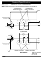
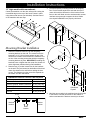
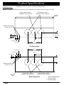
Dimensions
Product Specifications
Models EH48, MH48, EH54
All other models
See facing page
*
**
***
NOTE: The exhaust duct(s) and electrical wiring can be connected from either the top or the back of the hood.
Tolerances: +1/16”, -0 (1.6 mm, -0), unless otherwise stated.
Top Dimensions
Dual exhaust models*
Standard 8” duct connection
Single exhaust models**
Standard 8” duct connection
Front of
hood
1 ½” (3.8 cm)
3” (7.6 cm)
4” (10.2 cm)
9 7/8”
(25.1 cm)
6 1/8”
(15.6 cm)
19 ¾”
(50.2 cm
Electrical access holes
7/8” Dia. (5.1 cm)
C
L
Back Dimensions
Dual exhaust models*
Standard 8” duct connection
Single exhaust models**
Standard 8” duct connection
Bottom of
hood
¾” (1.9 cm)
4” (10.2 cm)
3” (7.6 cm)
Electrical access holes
7/8” Dia. (5.1 cm)
D ***
9 7/8”
(25.1 cm)
19 ¾”
(50.2 cm
C
L

5
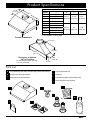
Parts List
2 temporary mounting brackets•
Temporary mounting hardware•
Hood assembly with filters (size and style varies with model)•
Blower mounting hardware (used only for installations •
requiring rear exhaust configuration
Light replacement tool•
Literature•
Light bulbs (quantity varies with model)•
Dacor Stainless Steel Cleaner•
Product Specifications
OVERALL DIMENSIONS
Model A B C D***
EH3012 29 7/8” (75.9 cm)
26 7/8”
(68.3 cm)
12 3/8”
(31.4 cm)
4 1/2”
(11.4 cm)
EH3612 35 7/8” (91.1 cm)
EH4212 41 7/8” (106.4 cm)
EH4812 47 7/8” (121.6 cm)
MH3012 29 7/8” (75.9 cm)
25 1/2”
(64.8 cm)
MH3612 35 7/8” (91.1 cm)
MH4812 47 7/8” (121.6 cm)
EH3018 29 7/8” (75.9 cm)
26 7/8”
(68.3 cm)
18”
(45.7 cm)
6 1/8”
(15.6 cm)
EH3618 35 7/8” (91.1 cm)
EH4218 41 7/8” (106.4 cm)
EH4818 47 7/8” (121.6 cm)
EH5418 53 7/8 (136.8 cm)
MH3018 29 7/8” (75.9 cm)
25 1/2”
(64.8 cm)
MH3618 35 7/8” (91.1 cm)
MH4818 47 7/8” (121.6 cm)
*** See diagram on facing page.
A
A
B
B
C
C
D
D
E
E
F
F
G
H
H
G
C
11 7/8”
(30.2 cm)
Overall
Dimensions
A
B
Dimensions of Optional
AHT10 Transition
For dual exhaust models, See
page 7 for more information
STAINLESS
STEEL
CLEANER
32”
(81.3 cm)
13 ¾”
(34.9 cm)
¾”
(1.9 cm)
9”
(22.9 cm)
2” (5.1 cm)

6
Planning the Installation
Cabinet Layout
WARNING
To reduce the risk of personal injury caused by reaching
over a hot appliance, cabinet storage space located
directly above the range should be avoided.
MINIMUM CABINET WIDTH
Models E
EH3012, EH3018, MH3012, MH3018 30” (76.2 cm)
EH3612, EH3618, MH3612, MH3618 36” (91.5 cm)
EH4212, EH4218 42” (106.7 cm)
EH4812, EH4818, MH4812, MH4818 48” (121.9 cm)
EH5418 54” (137.2 cm)
All tolerances: +1/16”, -0, unless otherwise stated
WARNING
Observe all governing codes and ordinances during planning and installation. Contact your local building department for
further information.
IMPORTANT
See the diagram for minimum installed distance from
the hood to the cooktop surface. The minimum specified
distance may be higher for the particular range or
cooktop in use. Check the manufacturers specifications
for the cooktop or range.
Carefully check the location where the hood is to be •
installed. The hood should be placed for convenient
access. Make certain that electric power can be provid-
ed in the selected location. The hood must be centered
horizontally over the cooktop/range.
The hood model selected must be as wide as the •
cooktop surface or wider.
Plan the installation so that all minimum dimensions are •
met or exceeded. Dimensions shown provide minimum
clearances, unless otherwise noted.
All contact surfaces between the hood and any cabi-•
nets or walls must be solid and at right angles.
Install the range hood and cooking appliance(s) so that •
they can be removed if service is required.
Power Supply
WARNING
The electric service to the range hood should be installed
only by a licensed electrician.
It is the owner’s responsibility to ensure that the electrical
connection of this appliance is performed by a qualified
electrician. The electrical installation, including minimum
supply wire size and grounding, must be in accordance
with the National Electric code ANSI/NFPA* (or latest revi-
sion) and local codes and ordinances.
*A copy of this standard may be obtained from:
National Fire Protection Association
1 Batterymarch Park
Quincy, Massachusetts 02269-9101
The ground terminal on the hood must be connected •
to a grounded, metallic, permanent wiring system or
grounding conductor installed by a licensed electrician.
Do not ground the appliance or appliance wiring to a •
gas pipeline or to the neutral (white) power supply wire.
Do not install a fuse in the neutral or ground circuit.•
Connect the hood directly to an electrical junction box. •
Hard-wire the hood according to local code directly to
a dedicated three wire grounded, single phase circuit
rated at 120 Vac 60 Hz, 15 Amp.
E
25” Min.
(63.5 cm)
Electrical
Access

7
Planning the Installation
WARNING
To reduce the risk of fire and to properly exhaust air, •
be sure to duct air outside the house or building. Do
not vent exhaust air into spaces within walls or ceil-
ings or into attics, crawl spaces or garages.
To prevent combustion by-products, smoke or odors •
from entering the home and to improve efficiency,
tape all duct joints securely.
Use only duct work constructed of materials deemed •
acceptable by state, municipal and local codes.
Range hoods may interrupt the proper flow of smoke •
and combustion gases from furnaces, gas water
heaters and fireplaces. To avoid drawing lethal gases
into the home, follow the manufacturer’s recom-
mendation for these devices and consult NFPA and
ASHRAE recommendations.
Failure to install a remote blower or proper duct work •
may result in a back draft and/or the insufficient vent-
ing of smoke and fumes.
DO NOT• install an additional in-line or external blow-
er to increase the length of the duct run. Even small
differences between blower air flow rates can greatly
reduce the air draw by the hood.
All duct work materials (including screws and duct tape) •
must be purchased separately by the customer. When
planning new duct work, always look for the shortest,
most direct route to the outside. The blower assembly
can be rotated to accommodate venting (and wiring)
through the top A or the back B .
The hood exhaust connects to an 8-inch round duct. •
You can increase the duct size over the duct run if
desired. To prevent a back draft, never decrease the
duct size over the run. If existing duct work is smaller
than 8 inches in diameter, remove it and replace it with
8-inch duct work.
Do not rely on tape alone to seal duct joints. Fasten all •
connections with sheet metal screws and tape all joints
with certified silver tape or duct tape. Use sheet metal
screws as require to support the duct weight.
To prevent back-drafts, a damper at the duct outlet may •
also be required.
Make sure duct work does not interfere with floor joists •
or wall studs.
On dual exhaust models, the two 8” exhausts may be •
merged into one 10” duct using Dacor transition kit
AHT10. See page 16 for details.
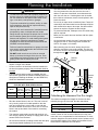
Calculating the Maximum Duct Run Length
The maximum straight duct length for the hood is deter-
mined by the type of duct used. See the chart below.
DUCT SIZE MAXIMUM DUCT RUN
8” round 60 feet
10” round 50 feet
3¼” X 10” rectangular 50 feet
For each elbow and transition added to the duct work, a
certain number of feet must be subtracted from the maxi-
mum duct run to compensate for wind resistance. To deter-
mine the length the duct work cannot exceed, subtract all of
the equivalent lengths of the elbows and transitions listed
below from the maximum duct run above.
Duct Work Equivalent Lengths
EQUIVALENT LENGTHS
Piece Subtract Piece Subtract
8” 90° elbow 7 feet 10” 90° elbow 5 feet
8” 45° elbow 3 feet 10” 45° elbow 2 feet
3¼” X 10”
to round 90°
transition
25 feet
3¼” X 10” to
8”/10” round
transition
4 feet
Roof cap *
Wall cap with
damper
*
* The equivalent lengths of roof and wall caps vary with
model and configuration. For equivalent length, contact the
manufacturer or a qualified HVAC specialist.
Duct Work Design Tips
Wherever possible, reduce the number of transitions and
turns to as few sharp angles as possible. Two staggered
45° angles are better than one 90°.
Keep turns as far away from the hood exhaust as possible,
and as much space between bends as possible.
For best performance, use round duct instead of rectangu-
lar, especially when elbows are required.
If multiple elbows are used, try to keep a minimum of 24”
straight duct between them.
Avoid “S” or “back to back” use of adjacent elbows.
In regions where the weather gets extremely cold, use ther-
mal breaks, such as a short section of non-metallic duct, to
avoid indoor heat loss. Locate the break as close as pos-
sible to the outside pass through point.
Do not use flexible metal duct.
Do not use duct work that is smaller in cross-sectional area
than the recommended types above.
A
B

8
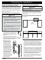
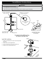
Electrical Service Installation
WARNING
The electric service to the range hood should be installed
only by a licensed electrician.
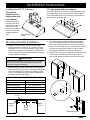
Install a junction box in the vicinity of the hood electri-
cal access holes according to local codes. Install it either
behind or above the hood. The diagram below shows sug-
gested locations.
Drill 7/8” holes in the wall or cabinet as necessary to allow
the wiring to pass through into the hood. See page 4 for
hole locations.
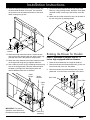
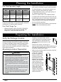
Duct Cutout
Using a pencil, draw the vertical center line for the 1.
range hood on the wall. Extend the line down 10” (25.4
cm) from where the top of the hood will be located.
The center line for the hood is usually halfway between
the cabinets at the installation location or the same as
the center line of the cooktop or range. The line will be
used to line up the mounting brackets during installa-
tion.
Locate the center lines for the duct cutout(s) according 2.
to the dimensions on page 4. For installations venting
through the top of the hood, use the top dimensions to
locate the center lines on the ceiling or cabinet bottom.
For installations venting through the back of the hood,
use the back dimensions to locate the center lines on
the back wall. See the diagrams on the right.
Cut a hole for the duct to pass through 11” (28 cm) in 3.
diameter. Center it on the center lines. Dual exhaust
models require two (2) holes.
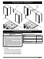
Preparing for Installation
Verify the Package Contents
Unpack the parts box and verify that all parts have been
included according to the parts list on page 5. If any item
is missing or damaged, please contact the dealer immedi-
ately. Do not install a damaged or incomplete appliance.
Make sure you have everything necessary for proper instal-
lation before proceeding.
Mounting Location Preparation
WARNING
The electrical service to the range hood should be •
installed only by a licensed electrician.
Observe all governing codes and ordinances during •
site preparation and installation. Contact your local
building department for further information.
Failure to properly anchor the hood to the wall may •
result in personal injury due to the unit falling off the
wall.
To avoid an electric shock hazard and property dam-•
age, locate electric wires and water pipes and avoid
drilling or cutting in the vicinity.
Use the temporary mounting brackets only to hold •
the hood in place until permanent anchoring is
installed.
Temporary mounting brackets, and the •
screws and anchors to hold them in place
during installation are provided with the
hood. Two anchors and screws are used
per bracket.
Determine the number, size and type of •
anchors required to attach the hood permanently to the
wall and/or the cabinets based on the type of installa-
tion and the weight chart on page 3.
Make sure the mount-•
ing surface is properly
reinforced to handle the
full weight of the hood.
If mounting the unit to a
drywall or plastered sur-
face, install a reinforced
mounting block between
the studs behind all hood
mounting locations. You
may attach screws directly
to the studs and cabinets
if they line up with the
mounting holes in the back
and top of the hood. If
mounting the hood to brick
or masonry, select anchors
capable of holding the full
weight of the hood.
Suggested
Electrical
Location
Hood
Location

9
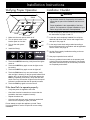
Preparing for Installation
Duct Cut-Out for Rear Venting
Back wall
Duct Cut-Out for Top Venting
Ceiling or
cabinet
bottom
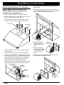
Installation Instructions
WARNING
Do not install the range hood unless the electrical •
service provided meets the range hood specifica-
tions.
Observe all governing codes and ordinances during •
installation. Contact your local building department
for further information.
A qualified technician must complete the installa-•
tion of this built-in appliance. More than one person
is required to raise the hood into place. The owner
is responsible to make sure the hood is properly
installed.
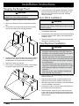
Start by removing the filters from the bottom of the 1.
hood. Put them in a safe location so that they will not
be damaged.
If the hood will be installed in a top exhaust configura-2.
tion, skip to page 16. If the hood will be installed so
that air will exhaust out of the back, the blowers must
be rotated into the correct position before hanging the
hood. The procedure for rotating the blower depends
on the hood model number. See the table at the right.
Blower Rotation Instructions
MODEL SEE PAGE
EH3012, MH3012, EH3612, MH3612,
EH4212
10
EH4812, MH4812 11
EH3018, MH3018, EH3618, MH3618,
EH4218
13
EH4818, MH4818, EH5418 15

10
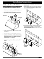
Installation Instructions
Rotating the Blower for Models:
EH3012, MH3012, EH3612, MH3612 and
EH4212 (Models that are 12 inches high
equipped with a single blower)
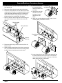
Place the hood assembly on a large flat surface.1.
Remove and save the four (4) screws and the duct col-2.
lar from the top of the unit. See below.
Remove and save the four (4) screws and the cover 3.
plate that covers the hole on the back of the hood.
Tip the hood back, so that it lays on its back with the 4.
front pointing up.
Remove the filters from the under side of the hood.5.
Locate the wiring harness. Cut the cable tie that takes 6.
up the slack in the cable. It is located behind the panel
on the right side inside the hood. Also cut the two (2)
cable ties that hold the wiring harness to the brace
inside the hood, on the right side. See below.
Remove and save the nut that holds the wiring harness 7.
cable clamp in place. Remove and save the clamp.
Disconnect the wiring harness connector from the 8.
blower motor.
While supporting the blower from below, remove the 9.
four (4) nuts that hold the blower and mounting plate in
place. Remove the blower from the hood.
Remove and discard 10.
the mounting plate
attached to the blower
motor.
Remove the four (4) 11.
nuts that hold the rear
mounting plate in place
and remove it. See
below.
Attach the mounting plate removed in step 11 (rear 12.
mounting plate) to the blower motor.
Cover Plate
Duct Collar
Rear Mounting
Plate
Remove
and discard
Remove
cable clamp
Remove
cable ties
Wiring
Harness

11
Tip the hood back down so that the top of the hood 17.
faces up. Using existing screws, attach the cover plate
removed in step 3 to the top of the hood to cover the
hole.
Attach the duct collar removed in step 2 to the back of 18.
the unit using four (4) existing screws.
Rotating the Blower for Models:
EH4812 and MH4812 (Models that are 12
inches high equipped with two blowers.
Place the hood assembly on a large flat surface.1.1.
Remove and save the screws and the two (2) duct col-2.
lars from the top of the unit. See below.
Remove and save the screws and the two (2) cover 3.
plates that cover the holes on the back of the hood.
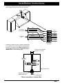
Insert the opening on the blower motor assembly into 13.
the hole inside the back of the hood. The connector
on the motor must be toward the bottom of the hood.
Attach it using four (4) nuts.
Route the wiring harness as shown. Secure the har-14.
ness to the motor assembly with the cable clamps sup-
plied with the hood in the positions shown below.
Attach the wiring harness to the brace inside the hood, 15.
on the right side using two (2) supplied cable ties.
Use a cable tie to take up any remaining slack that may 16.
exist in the wiring harness. Stow the harness behind
the plate on the right side. Securing any slack will
reduce additional noise due to vibration.
Installation Instructions
Connector
location
Cover Plate
Duct Collar
Cable
Clamps
Wiring
Harness
Cable
Ties
Cable tie if
necessary
IMPORTANT: For proper
operation, route and secure
the harness exactly as shown.

12
Remove and discard 10.
the mounting plates
attached to both blow-
er motors.
Remove the nuts that 11.
hold the rear mount-
ing plates in place
and remove. See
below.
Attach the mounting plates removed in step 11 (rear 12.
mounting plate) to the blower motors.
Insert the opening of each blower motor assembly into 13.
the holes inside the back of the hood. The connector
on the motors must be toward the bottom of the hood.
Attach them with four (4) nuts each.
Installation Instructions
Tip the hood back, so that it lays on its back with the 4.
front pointing up.
Remove the filters from the under side of the hood.5.
Locate the wiring harness. Cut the cable tie that takes 6.
up the slack in the cable. It is located behind the panel
on the right side inside the hood. Also cut the two (2)
cable ties that hold the wiring harness to the brace
inside the hood, on the right side. See below.
Remove and save all the nuts that hold the wiring har-7.
ness cable clamps in place. Remove and save the
clamps.
Disconnect both wiring harness connectors from the 8.
blower motors.
While supporting each blower from below, remove the 9.
four (4) nuts that hold the blower and mounting plates
in place. Remove both blowers from the hood.
Remove cable
clamps
Remove
cable ties
Wiring Harness
Connector
locations
Remove
and discard
Rear Mounting
Plate

13
Route the wiring harness as shown below. Secure 14.
the harness to the motor assemblies using the cable
clamps supplied with the hood in the positions shown.
Attach the wiring harness to the brace inside the hood, 15.
on the right side using two (2) supplied cable ties.
Use a cable tie to take up any remaining slack that may 16.
exist in the wiring harness. Stow the harness behind
the plate on the right side. Securing any slack will
reduce additional noise due to vibration.
Tip the hood back down so that the top of the hood 17.
faces up. Using existing screws, attach the cover plates
removed in step 3 to the top of the hood to cover the
holes.
Attach the duct collars removed in step 2 to the back of 18.
the unit using the existing screws.
Installation Instructions
Rotating the Blower for Models:
EH3018, MH3018, EH3618, MH3618, EH4218
(Models that are 18 inches high equipped with
a single blower)
Place the hood assembly on a large flat surface.1.
Remove and save the four (4) screws and the duct col-2.
lar from the top of the unit.
Remove and save the four (4) screws and the cover 3.
plate that covers the hole on the back of the hood.
Tip the hood back, so that it lays on its back with the 4.
front pointing up.
Remove the filters from the under side of the hood.5.
Locate the wiring harness. Cut the cable tie that takes 6.
up the slack in the cable. It is located behind the panel
on the right side inside the hood. Also cut the two (2)
cable ties that hold the wiring harness to the brace
inside the hood, on the right side.
Remove and save the nut that holds the wiring harness 7.
cable clamp in place. Remove and save the clamp.
Duct Collar
Cover Plate
Remove
cable clamp
Remove
cable ties
Wiring
Harness
Cable
Clamps
Wiring
Harness
Cable
Ties
Cable tie if
necessary
IMPORTANT: For proper
operation, route and secure
the harness exactly as shown.

14
Installation Instructions
Disconnect the wiring harness connector from the 8.
blower motor.
While supporting the blower from below, remove the 9.
four (4) nuts that hold the blower in place. Remove the
blower from the hood.
Insert the opening on the blower motor into the hole 10.
inside the back of the hood. The connector on the
motor must be toward the bottom of the hood. Attach it
using four (4) nuts.
Route the wiring harness as shown. Secure the har-11.
ness to the motor assembly with the cable clamps sup-
plied with the hood in the positions shown below.
Attach the wiring harness to the brace inside the hood 12.
on the right side using two (2) supplied cable ties.
Use a cable tie to take up any remaining slack that may 13.
exist in the wiring harness. Stow the harness behind
the plate on the right side. Securing any slack will
reduce additional noise due to vibration.
Tip the hood back down so that the top of the hood 14.
faces up. Using four (4) existing screws, attach the
cover plate removed in step 3 to the top of the hood to
cover the hole.
Attach the duct collar removed in step 2 to the back of 15.
the unit using the four (4) existing screws.
Connector
location
Cable
Clamps
Wiring
Harness
Cable
Ties
Cable tie if
necessary
IMPORTANT: For proper
operation, route and secure
the harness exactly as shown.

15
Installation Instructions
Rotating the Blower for Models:
EH4818, MH4818 and EH5418 (Models that are
18 inches high equipped with two blowers.
Place the hood assembly on a large flat surface.1.
Remove and save the screws and the two (2) duct col-2.
lars from the top of the unit.
Remove and save the screws and the two (2) cover 3.
plates that cover the holes on the back of the hood.
Tip the hood back, so that it lays on its back with the 4.
front pointing up.
Remove the filters from the under side of the hood.5.
Locate the wiring harness. Cut the cable tie that takes 6.
up the slack in the cable. It is located behind the panel
on the right side, inside the hood. Also cut the two (2)
cable ties that hold the wiring harness to the brace
inside the hood, on the right side.
Remove and save all the nuts that hold the wiring har-7.
ness cable clamps in place. Remove and save the
clamps.
Disconnect both wiring harness connectors from the 8.
blower motors.
While supporting each blower from below, remove the 9.
four (4) nuts that hold each blower in place. Remove
both blowers from the hood.
Insert the opening of each blower motor into the holes 10.
inside the back of the hood. The connector on the
motors must be toward the bottom of the hood. Attach
them with four (4) nuts each.
Cover Plate
Duct Collar
Remove cable
clamps
Remove
cable ties
Wiring Harness
Connector
locations

16
AHT10 Transition Kit Installation
On dual exhaust models, the two 8” exhausts may be
merged into one 10” duct using Dacor transition kit AHT10.
Install the transition before installing the hood on the wall. It
connects to the hood on the top or rear, depending on the
type of installation.
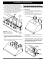
Preparing the AHT10 for Installation
Prepare the transition for installation by bending the bot-
tom edges at right angles to create a ¾” flange around the
base. IMPORTANT: On 12” high hoods modified to exhaust
out the rear, leave one of the long edges unbent.
Drill pilot holes around the edges of the mounting flange
including the unmodified edge, if the transition will be
mounted to the back of a 12” high hood (see above).
Installing the AHT10 Transition:
Top exhaust models and 18” high models with
rear exhaust:
Center the transition
over the duct collars
and fasten it in place
using sheet metal
screws (not included).
Seal the base of the
transition with duct
tape.
Route the wiring harness as shown. Secure the har-11.
ness to the motor assemblies using the cable clamps
supplied with the hood in the positions shown below.
Attach the wiring harness to the brace inside the hood, 12.
on the right side using two (2) supplied cable ties.
Use a cable tie to take up any remaining slack that may 13.
exist in the wiring harness. Stow the harness behind
the plate on the right side. Securing any slack will
reduce additional noise due to vibration.
Tip the hood back down so that the top of the hood 14.
faces up. Using existing screws, attach the cover plates
removed in step 3 to the top of the hood to cover the
holes.
Attach the duct collars removed in step 2 to the back of 15.
the unit using the existing screws.
Installation Instructions
Cable
Clamps
Wiring
Harness
Cable
Ties
Cable tie if
necessary
IMPORTANT: For proper
operation, route and secure
the harness exactly as shown.
Transition Flange Prep:
All models using top
exhaust and 18” high
models with rear exhaust
Transition Flange Prep:
12” high models with rear
exhaust
Leave this edge unmodified,
bend up other three.
Top mounting
shown

17
Installation Instructions
12” high models with rear exhaust:
Center the transition over the duct collars while resting the
unmodified edge on the top of the hood. Fasten in place
using sheet metal screws (not included). Seal the base of
of the transition with duct tape.
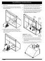
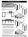
Mounting Bracket Installation
Draw the horizontal center line for the temporary 1.
mounting brackets on the wall. The center line for the
brackets is 2 1/8” (54 cm) below where the top of the
hood will be located. The horizontal line marks the cen-
ter line of the mounting screws that hold the temporary
mounting brackets in place. IMPORTANT: Installing the
brackets lower or higher than the center line shown will
cause alignment problems during final installation.
Draw the two (2) vertical center lines for the brackets 2.
on the wall. They are located on both sides of the hood
center line drawn on the wall before making the duct
cut-out. The distance from the center line depends on
the model. See the chart below.
TEMPORARY BRACKET CENTER LINE DISTANCE
Models F
EH3012, EH3018, MH3012, MH3018 12 3/8” (31.4 cm)
EH3612, EH3618, MH3612, MH3618 15 3/8” (39.1 cm)
EH4212, EH4218 18 3/8” (46.7 cm)
EH4812, EH4818, MH4812, MH4818 21 3/8” (54.3 cm)
EH5418 24 3/8” (61.9 cm)
2 1/8”
Bracket
location
Bracket
location
Hood
location
F F
Reinforced
Drywall
Find the temporary mounting bracket in the shipping 3.
box. Put the bracket against the wall and line up the
center hole with the intersection of the bracket center
lines on the wall. Make sure the anchors and/or screws
used are strong enough to support the hood. Make
sure drywall installations are properly reinforced.
Mark the two mounting hole positions through the holes 4.
in the bracket. Drill the pilot holes for the screws or
anchors and attach the brackets securely to the wall.

18
Installation Instructions
Duct Work Installation
WARNING
During duct installation, make sure there are no
obstructions that keep the damper flaps on the top of the
hood from opening.
Install the duct work starting from the hood, working •
toward the outside vent. Observe the specifications on
page 7.
Fasten all joints with sheet metal screws and seal with •
duct tape or certified silver tape.
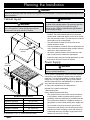
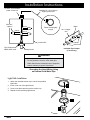
Hanging the Range Hood
WARNING
Hanging the range hood requires two people. Do not
attempt to lift the hood without assistance.
Remove the plastic coating from the outside of the 1.
hood.
Remove the filter(s) to reduce weight and avoid dam-2.
age.
Lift the hood up on both sides and slip the mounting 3.
slots over the tabs on the mounting brackets.
Lift the hood into its final position and mark the desired 4.
locations for the anchors or wood screws through the
mounting slots on the back and top of the hood.
Remove the hood from the wall.5.
Drill the pilot or mounting anchor holes. If using mount-6.
ing anchors insert them into the mounting holes.
Reattach the hood to the temporary mounting brackets.7.
Lift the hood into its final position and fasten it in place. 8.
Insert the fasteners through the mounting slots in the
back and top of the hood into the studs, mounting
blocks or anchors.
Mounting Hole Locations
Page is loading ...
Page is loading ...
Page is loading ...
Page is loading ...
Page is loading ...
Page is loading ...
Page is loading ...
Page is loading ...
Page is loading ...
Page is loading ...
Page is loading ...
Page is loading ...
Page is loading ...
Page is loading ...
Page is loading ...
Page is loading ...
Page is loading ...
Page is loading ...
Page is loading ...
Page is loading ...
Page is loading ...
Page is loading ...
Page is loading ...
Page is loading ...
Page is loading ...
Page is loading ...
Page is loading ...
Page is loading ...
-
 1
1
-
 2
2
-
 3
3
-
 4
4
-
 5
5
-
 6
6
-
 7
7
-
 8
8
-
 9
9
-
 10
10
-
 11
11
-
 12
12
-
 13
13
-
 14
14
-
 15
15
-
 16
16
-
 17
17
-
 18
18
-
 19
19
-
 20
20
-
 21
21
-
 22
22
-
 23
23
-
 24
24
-
 25
25
-
 26
26
-
 27
27
-
 28
28
-
 29
29
-
 30
30
-
 31
31
-
 32
32
-
 33
33
-
 34
34
-
 35
35
-
 36
36
-
 37
37
-
 38
38
-
 39
39
-
 40
40
-
 41
41
-
 42
42
-
 43
43
-
 44
44
-
 45
45
-
 46
46
-
 47
47
-
 48
48


Dacor EH42 User manual
- Type
- User manual
Ask a question and I''ll find the answer in the document
Finding information in a document is now easier with AI
Related papers
-
Dacor AEHK2CP Planning Guide [337 KB]
-
-
Dacor Stove EH42 User manual
-
-
-
-
-
-
-