Page is loading ...

1
WARNING: To ensure the drive is not unexpectedly
started, turn off and lock-out or tag power source before
proceeding. Failure to observe these precautions could
result in bodily injury.
WARNING: All products over 25 kg (55 lbs) are noted on the
shipping package. Proper lifting practices are required for
these products.
Instruction and Lubrication Manual for
Dodge® Grid-Lign Flexible Couplings
Includes ATEX Approved Couplings
Sizes: 1020-1200T10 (Close Coupled, Horizontally Split Cover),
T20 (Close coupled, Vertically Split Covers), T31 (Full Spacer Type), T35 (Half Spacer Type)
These instructions must be read thoroughly before installation or operation. This instruction manual was accurate at the time of
printing. Please see baldor.com for updated instruction manuals.
Note! The manufacturer of these products, Baldor Electric Company, became ABB Motors and Mechanical Inc. on
March 1, 2018. Nameplates, Declaration of Conformity and other collateral material may contain the company name of
Baldor Electric Company and the brand names of Baldor-Dodge and Baldor-Reliance until such time as all materials have
been updated to reflect our new corporate identity.
WARNING: Because of the possible danger to person(s) or
property from accidents which may result from the improper
use of products, it is important that correct procedures be
followed. Products must be used in accordance with the
engineering information specified in the catalog. Proper
installation, maintenance and operation procedures must
be observed. The instructions in the instruction manuals
must be followed. Inspections should be made as necessary
to assure safe operation under prevailing conditions. Proper
guards and other suitable safety devices or procedures as
may be desirable or as may be specified in safety codes
should be provided, and are neither provided by ABB nor
are the responsibility of ABB. This unit and its associated
equipment must be installed, adjusted and maintained by
qualified personnel who are familiar with the construction
and operation of all equipment in the system and the
potential hazards involved. When risk to persons or property
may be involved, a holding device must be an integral part
of the driven equipment beyond the speed reducer output
shaft.
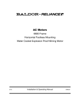
Step 3: Mounting Hubs
Fit hubs with ends of shaft per the following recommendations:
Hub
Seal
T10 Hub Mounting
Hub
Cover half
with Seal
T20 Hub Mounting
Figure 1 - Hub Mounting
NOTE: When mounting T10 couplings, seals must be
installed prior to mounting shaft hubs. Lightly grease each
of the two seals from the grid and cover assembly. Place
each seal far back on its respective shaft.
NOTE: When mounting T20 coupling, cover halves
including seals, must be mounted prior to mounting shaft
hubs. Remove lube plugs from each cover half and insert
the two seal rings into each cover. Lightly coat seals with
grease. Place cover halves as far back as respective shafts
will allow with flanges facing each other.
INSTALLATION:
Step 1: Pre-Assembly Inspection
All parts should be examined for any damage during the
shipping and handling process. Measurements should be taken
to ensure parts meet application requirements, such as hub and
shaft ts, shaft separation, etc. All parts must be clean and free
of any foreign material before attempting assembly.
Step 2: Installation of Keys
Install keys in respective shafts. Keys should t keyseat with a
tight t on the sides and slight clearance over the key.

2
A. Interference Fit Use a scribe to mark the desired hub
location on shafts. Using an oven or oil bath, heat hubs
evenly to 350°F (204°C). To avoid distortion, do not exceed
450°F (232°C). Slide heated hubs onto shafts and align
with the scribed marks. Allow the hubs to cool to room
temperature before installing grid segment(s).
B. Clearance Fit Slip hub onto shaft and tighten set screws
to value listed in Table 1. Setscrews should be checked
periodically for tightness.
C. Taper Bored hubs do not require preheating for assembly.
Mount hub and align on shaft before drawing up on shaft
the required distance. In most applications, the hub face will
project beyond the small end of the shaft taper. Lock hub in
place with proper locking device provided with shaft.
D. TAPER-LOCK
®
hubs are available for T10, T20, T31 and T35
style couplings for light and medium applications. Install per
instructions for the TAPER-LOCK bushings (MN4044).
Step 4: Set Shaft Spacing
Shaft Separation for T10 and T20 couplings should be set
per appropriate “G” dimensions in Table 2. For T31 and 35
couplings, refer to the BSE (between shaft ends) dimension in
Table 2. For the T31 and T35, use the G dimension for checking
the coupling gap after the BSE is set.
Gap (G)
Figure 2 - Shaft Separation
Table 1 - Set Screw Installation for Clearance Fit Grid-Lign Hubs
Coupling Size Bore Range Set Screw Size Allen Wrench Size Torque (ft-lbs) Torque (N-m)
1020T
1/2 - 7/8 1/4-20 1/8 7 9
15/16 - 1-1/8 8-32 5/64 2 3
1030T 5/8 - 1-3/8 1/4-20 1/8 7 9
1040T 7/8 - 1-5/8 1/4-20 1/8 7 9
1050T 7/8 - 1-7/8 1/4-20 1/8 7 9
1060T
15/16 - 1-3/8 1/4-20 1/8 7 9
1-7/16 - 2-1/8 3/8-16 3/16 24 32
1070T
1-1/4 - 1-3/8 1/4-20 1/8 7 9
1-7/16 - 2-5/8 3/8-16 3/16 24 32
1080T 1-1/2 - 3 3/8-16 3/16 24 32
1090T 1-1/2 - 3-3/4 3/8-16 3/16 24 32
Table 2 - Recommended Operating Misalignment
Size
Misalignment Limits ① Coupling Gap - “G” BSE (Shaft Spacing) for T31 BSE (Shaft Space) for T35
Spacer Flange
Bolt Tightening
Torque
Cover bolt
Tightening
Torque for Type
T20, T10, T31,
T35
Lubrication
Weight
Parallel Angular
Type T20,
T10 T35
Type T31 Min. Max. Min. Max
in. mm in. mm in. mm in. mm in. mm in. mm in. mm in. mm (lb.-in.) (Nm) (lb.-in.) (Nm) Lbs. Kg
1020T 0.005 0.13 0.005 0.13 0.125 3.18 0.188 4.78 3.50 88.9 8.00 203.2 1.78 45.2 4.03 102.4 120 14 100 11 0.06 0.03
1030T 0.005 0.13 0.005 0.13 0.125 3.18 0.188 4.78 3.50 88.9 8.50 215.9 1.78 45.2 4.28 108.7 120 14 100 11 0.06 0.03
1040T 0.005 0.13 0.005 0.13 0.125 3.18 0.188 4.78 3.50 88.9 8.50 215.9 1.78 45.2 4.28 108.7 120 14 100 11 0.12 0.05
1050T 0.005 0.13 0.005 0.13 0.125 3.18 0.188 4.78 4.38 111.3 8.50 215.9 2.22 56.4 4.28 108.7 250 28 200 23 0.12 0.05
1060T 0.010 0.25 0.010 0.25 0.125 3.18 0.188 4.78 5.00 12 7.0 13.00 330.2 2.53 64.3 6.53 165.9 440 50 200 23 0.25 0.11
1070T 0.010 0.25 0.010 0.25 0.125 3.18 0.188 4.78 5.00 12 7.0 13.00 330.2 2.53 64.3 6.53 165.9 440 50 200 23 0.25 0.11
1080T 0.010 0.25 0.010 0.25 0.125 3.18 0.188 4.78 7.25 184.2 16.00 406.4 3.66 93.0 8.03 204.0 825 93 200 23 0.38 0.17
1090T 0.012 0.30 0.012 0.30 0.125 3.18 0.188 4.78 7.25 184.2 16.00 406.4 3.66 93.0 8.03 204.0 1640 185 200 23 0.56 0.25
1100T 0.012 0.30 0.012 0.30 0.188 4.78 0.250 6.35 8.00 203.2 16.00 406.4 3.93 99.8 7.93 201.4 2940 332 260 29 0.94 0.43
1110T 0.012 0.30 0.012 0.30 0.188 4.78 0.250 6.35 8.25 209.6 16.00 406.4 4.80 121.9 7. 9 3 201.4 2940 332 260 29 1.12 0.51
1120T 0.012 0.30 0.012 0.30 0.375 9.53 0.375 9.53 9.69 246.1 16.00 406.4 5.78 146.8 7.65 194.3 8160 922 650 73 1.60 0.73
1130T 0.012 0.30 0.012 0.30 0.375 9.53 0.375 9.53 10.12 257.0 16.00 406.4 6.53 165.9 7.90 200.7 11640 1315 650 73 2.00 0.91
1140T 0.012 0.30 0.012 0.30 0.375 9.53 0.375 9.53 10.50 266.7 16.00 406.4 7.4 0 188.0 7.90 200.7 16320 1844 650 73 2.50 1.13
1150T 0.012 0.30 0.016 0.41 0.375 9.53 0.375 9.53 13.50 342.9 14.75 374.7 6.65 168.9 7.28 184.9 5400 610 650 73 4.30 1.95
1160T 0.012 0.30 0.018 0.46 0.375 9.53 0.375 9.53 13.50 342.9 16.00 406.4 6.65 168.9 7.9 0 200.7 5400 610 650 73 6.20 2.81
1170T 0.012 0.30 0.020 0.51 0.375 9.53 0.375 9.53 15.00 381.0 17.50 444.5 7.4 0 188.0 8.65 219.7 8160 922 1300 147 7.70 3.49
1180T 0.015 0.38 0.022 0.56 0.375 9.53 0.375 9.53 15.75 400.1 19.31 490.5 7.78 197.6 9.56 242.8 11640 1315 1300 147 8.30 3.76
1190T 0.015 0.38 0.024 0.61 0.375 9.53 0.375 9.53 16.00 406.4 20.88 530.4 8.00 203.2 10.34 262.6 16320 1844 1300 147 9.70 4.40
1200T 0.015 0.38 0.027 0.69 0.375 9.53 0.375 9.53 17.5 0 444.5 22.50 571.5 8.80 223.5 11.15 283.2 16320 1844 2300 260 12.40 5.62
① These are recommended installation misalignment limits. As operating misalignment increases, coupling life is reduced.

3
Step 5: Alignment
Angular Alignment
NOTE: Proper alignment yields the longest service life.
A. Instrument Method of checking alignment is recommended
since it is most accurate. Rigidly attach dial base to one of
the hubs and indicator needle against a face of the other
hub. Rotate both hubs 360°. Take indicator reading at four
points, 90°apart. Adjust alignment until all four readings are
within angular misalignment limits given in Table 2. To check
alignment, relocate the dial base to the opposite hub and
repeat the procedure.
B. Caliper / Feeler Gauge Method may be used if dial
indicator is not available or shaft gap is too small; however,
it is not the recommended method of checking alignment.
Check with calipers or feeler gauge at four points, 90°apart.
Adjust alignment until all four readings are within angular
misalignment limits as shown in Table 2.
Figure 3 - Angular Alignment Feeler Gauge Method
Parallel Alignment
A. Instrument Method of checking alignment is recommended
since it is most accurate. Rigidly attach dial base to one
hub and set dial indicator needle in contact with an outside
diameter of opposite hub. Rotate both hubs 360°. Take
indicator reading at four points 90° apart. Adjust alignment
until all four readings are within parallel misalignment limits
given in Table 2. To check alignment, relocate dial base on
opposite hub and repeat the procedure. Recheck angular
alignment.
B. A Straight Edge and Feeler Gauge may be used if a dial
indicator is not available; however, it is not recommended
as the most accurate method of checking alignment. Adjust
alignment until straight edge appears to be resting squarely
on both outside tooth diameters. Repeat procedure at 3
additional points,90°apart. Refer to Table 2 for limits of
parallel misalignment. Recheck angular alignment.
Figure 4 - Parallel Alignment Straight Edge Method
Step 6: Assembly of Element Grid
A. Assembly of T10 (Close coupled, horizontally split cover)
coupling:
a. Before inserting grid, hand pack hub teeth with
lubricant provided. Dodge Coupling Grease is
recommended for use with Grid-Lign (Refer to Tables
2 for recommendations on quantity of lubricant.) Fit
grid over hubs and starting at one end, work coils of
grid between the teeth. Seat with a soft mallet. If grids
are supplied in more than one segment, install so that
all cut ends extend in the same direction.
b. Hand pack more lubricant around the grid and
between the spaces of the grid after it is installed.
Refer to Step 7 for important information on
lubrication.
CAUTION: Do not overpack coupling with grease.
Grease Packing
Grid Insertion
Figure 5 - Grease Packing and Grid Insertion
c. Position the two cover seals on the hub and align with
the grooves in the half cover. Place gaskets on anges
of bottom cover half. Assemble cover with match
marks on same side. Install fasteners in cover halves
with nut end of bolt nearest lube plug. (In this position,
nuts are self retaining and do not require a wrench.)
Tighten per T10 cover bolt tightening torque as shown
in Table 2. (Sizes 1020-1090 have nut locking ats in
cover.)
NOTE: T10 coupling may be mounted on vertical or inclined
shafts. When doing so, assemble cover halves with anti-
rotation lug and match mark up or on the higher side. (See
Figure 6)

4
Lug
Anti-Rotation Lug
Match
Mark
Cover Match Marks
Figure 6 - Anti-Rotation Lug and Cover Match Mark
B. Assembly of T20 (Close coupled, vertically split cover)
coupling:
a. Lubricate and install grid per Step 5Aa for T10.
b. Bring together the T20 vertical cover halves with gasket
positioned between them, aligning all bolt holes. Lube
holes should be 180°apart. Tighten bolts to tightening
torque given in Table 2.
C. Assembly of T31 (Full Spacer) and T35 (Half Spacer):
a. The T31 and T35 seals and covers are mounted after
the rigid shaft hubs are in place.
b. Set shaft spacing per appropriate BSE dimensions per
Table 2.
c. Carefully stretch cover seals over teeth and onto spacer
hub. Bolt each half spacer hub onto rigid shaft hubs and
torque to specications given in Table 2 (Spacer Flange
Bolt Tightening Torque).
d. Lubricate and install grid per Step 5Aa for T10.
e. Position cover seals on hubs and assemble cover with
seals and gaskets per Step 5Ab.
f. To remove spacer with cover, loosen rigid hub bolts
and compress spacer hubs to disengage pilots.
Center section of spacer coupling will drop out without
disturbing driver or driven shafts.
NOTE: Install coupling guard per OSHA or applicable
requirements. Guarding should be designed so that the
coupling cover or element will be contained within the
guard in the event that the coupling cover or element is
thrown from the coupling assembly.
Step 7: Lubrication
Remove both lube plugs in cover and insert lube ttings. Pump
in the appropriate amount of Dodge Coupling Grease as shown
in Table 2, until it is forced out of the opposite lube hole. Then
install both lube plugs back into cover. See Table 3 for Dodge
Coupling Grease options.
NOTE: All lube plugs must be installed before operating
coupling.
NOTE: Proper lubrication of all types of GRID-LIGN
couplings is necessary for their efficient operation and
long service life.
NOTE: Successful operation is dependent upon adequate
lubrication. Precaution should be taken during handling
and recycling grease, oil or water glycol mixtures.
Table 3 - Dodge Coupling Grease Options
DODGE Part Number Description
012995 DODGE Coupling Grease - 14 Ounce Cartridge
012996 DODGE Coupling Grease - 14 Ounce Cartridge (10 Pack)
012997 DODGE Coupling Grease - 14 Ounce Cartridge (30 Pack)
012927 DODGE Coupling Grease - 35 Pound Pail
012928 DODGE Coupling Grease - 120 Pound Keg
012929 DODGE Coupling Grease - 400 Pound Drum
*See Table 2 for lubrication weight required per coupling size
Dodge Coupling Grease is supplied as standard on Dodge
Grid-Lign coupling sizes 1020T through 1090T.
Step 8: Maintenance
Maintenance is recommended every 6 months to ensure long
life. Disassemble coupling, remove old lubricant and clean.
Visually inspect all parts. Replace any worn parts. Hand pack
coupling with lubricant and repeat Step 6.
Step 9: Grid Removal
When it is necessary to disassemble coupling, remove cover
halves. Beginning at a cut end of grid, carefully insert a small
pry bar into loop. Using the teeth for leverage, gradually pry the
grid up, alternating sides while working around the coupling.
Figure 8 - Grid Removal
Interchange Information
The Dodge Grid-Lign exible couplings are designed to be
interchangeable with other tapered grid style couplings. See
Table 4 for more information.

5
Table 4 - Tapered Grid Coupling Nomenclature Interchange
Coupling with Horizontally Split Covers Coupling with Vertically Split covers
DODGE Falk DODGE Falk
1020T10 20T10 1020T10 1020T20 20T20 1020T20
1030T10 30T10 1030T10 1030T20 30T20 1030T20
1040T10 40T10 1040T10 1040T20 40T20 1040T20
1050T10 50T10 1050T10 1050T20 50T20 1050T20
1060T10 60T10 1060T10 1060T20 60T20 1060T20
1070T10 70T10 1070T10 1070T20 70T20 1070T20
1080T10 80T10 1080T10 1080T20 80T20 1080T20
1090T10 90T10 1090T10 1090T20 90T20 1090T20
1100T10 100T10 1100T10 1100T20 100T20 1100T20
1110T10 110T10 1110T10 1110T20 110T20 1110T20
1120T10 120T10 1120T10 1120T20 120T20 1120T20
1130T10 130T10 1130T10 1130T20 130T20 1130T20
1140T10 140T10 1140T10 1140T20 140T20 1140T20
1150T10 150T10 1150T10 1150T20 150T20 1150T20
1160T10 160T10 1160T10 1160T20 160T20 1160T20
1170T10 170T10 1170T10 1170T20 170T20 1170T20
1180T10 180T10 1180T10 1180T20 180T20 1180T20
1190T10 190T10 1190T10 1190T20 190T20 1190T20
1200T10 200T10 1200T10 1200T20 200T20 1200T20
Table 4 - Tapered Grid Coupling Nomenclature Interchange
Spacer Coupling Half Spacer Coupling
DODGE Falk DODGE Falk
1020T31 20T31 1020T31 1020T35 20T35 1020T35
1030T31 30T31 1030T31 1030T35 30T35 1030T35
1040T31 40T31 1040T31 1040T35 40T35 1040T35
1050T31 50T31 1050T31 1050T35 50T35 1050T35
1060T31 60T31 1060T31 1060T35 60T35 1060T35
1070T31 70T31 1070T31 1070T35 70T35 1070T35
1080T31 80T31 1080T31 1080T35 80T35 1080T35
1090T31 90T31 1090T31 1090T35 90T35 1090T35
1100T31 100T31 1100T31 1100T35 100T35 1100T35
1110T31 110T31 1110T31 1110T35 110T35 1110T35

6
ATEX Certification
These instructions do not cover all details or variations in
equipment nor provide every possible contingency or hazard
to be met in connection with installation, operation, and
maintenance. Should further information be desired, or should
particular problems arise which are not covered in this manual,
the matter should be referred to your local ABB representative.
DODGE GRID-LIGN couplings are manufactured under
guidelines of the ATEX directive 2014/34/EU. DODGE GRID-
LIGN Type T10, Type T31 and Type T35 couplings are suitable
for ATEX category 2 Group II for dust and gas environments
with ignition temperatures higher than T3 = 200°C for all
sizes. DODGE GRID-LIGN Type T20 couplings are suitable
for ATEX category 2 and M2, Group II and I for gas and dust
environments and also suitable for ATEX category 3 for all gas
or dust environments with ignition temperatures higher than T3
= 200°C for all sizes. A UL Certied adhesive label indicating
ATEX certication will be attached to the product and will
contain the following depending on coupling type.
ATEX Marking Information
A sticker indicating ATEX Certication will be attached to the
product and will be similar to the following:
For coupling types T10, T31 and T35
• II 2 GD c 200°C (T3)
• Tamb -30°C to +50°C
• SIRA 16ATEX6169X
• DODGE GRID-LIGN Coupling
• MFG by ABB Motors and Mechanical Inc.
• Greenville, SC/Ft. Smith, AR USA
For coupling types T20
• II 2 GD c 200°C (T3)
• I M2 c 200°C
• Tamb -30°C to +50°C
• SIRA 16ATEX6169X
• DODGE GRID-LIGN Coupling
• MFG by ABB Motors and Mechanical Inc.
• Greenville, SC/Ft. Smith, AR USA
Hazardous Area Use
For hazardous area use, the following potential ignition hazards
have been identied:
• Impact of outer enclosures
• Heat generation from exing or breaking of the internal grid
due to excessive torque and/or misalignment
• Frictional sparking from contact with stationary parts either
by coupling failure or incorrect installation
These potential hazards have been addressed by the materials
and design of the coupling and rely on correct installation and
maintenance, as detailed in the equipment instructions.
WARNING: These couplings are designed to operate with
surface temperatures below 200°C when properly installed
and selected. Excessive temperatures greater than 80°C is
a result of an abnormal operating condition caused by:
1. Improper installation – refer to installation manual for
proper procedures
2. Excessive misalignment – re-align coupling/shafts
3. Failure of the coupling grid – replace grid
4. Excessive speed – re-evaluate application and selection
5. Excessive vibration – determine source, re-evaluate
application
If applied in a Division 1 or Zone 1 environment, the excessive
temperature may cause ignition of hazardous materials.
In hazardous environments, DODGE GRID-LIGN couplings
should not be considered as fail safe or “break-away” power
transmission devices. Overloads imposed to these devices
could cause irreparable damage, shall be considered an
explosive hazard, could create projectiles, and/or could cause
torque transmission interruptions. The coupling shall be sized
and used to the stated torque and speed capabilities of the
unit as published in the DODGE PT Components Engineering
Catalog. Any assistance needed in selection shall be
referenced to an ABB representative.
Additional Instruction for Safe Installation and Use
The coupling must be installed and operated in accordance
with the below instructions and the certicate “special
conditions of safe use” to ensure that the maximum
temperatures are not exceeded and the coupling is not subject
to impact.
1. All rotating parts should be guarded to prevent contact with
foreign objects which could result in sparks, ignition, or
damage to the coupling.
2. Couplings should be periodically inspected for normal
wear, dust/dirt buildup, bends or breaks in the grid, or any
similar scenario that would impede heat dissipation.
3. Increasing levels of vibration and noise could indicate the
need for inspection, repair or replacement of the coupling
or element.
4. Electrical sparks are a source of ignition. To reduce risk,
proper electrical bonding and grounding is recommended.
5. Overloading may result in breakage or damage to the grid
or other equipment. As a result the coupling could become
an explosion hazard. Damaged coupling components must
not be operated in hazardous environments.
6. The DODGE GRID-LIGN coupling is not intended to be
used as thrust bearing member.
7. Coupling guards should have a minimum of 2” clearance
over the DODGE GRID-LIGN coupling.
8. The coupling shall be suitably protected from impact by
falling objects.
9. When choosing equipment for Group 1 applications, the
user shall take account of the inuence on the smouldering
temperature of coal dusts where they may be deposited
in a layer on surfaces which may reach a temperature of
150°C (300°F) and above.

7
Document Control Number: DOC-BEZ-DA-M27-B-EN.DOC 1 / 1
EU Declaration of Conformity
The undersigned, representing the following supplier and the following authorised representative-
Baldor Electric Company
5711 R. S. Boreham, Jr. Street
Fort Smith, Arkansas 72901
USA
ABB Automation Products GmbH
Oberhausener Straße 33
40472 Ratingen, Germany
This declaration is issued under the sole responsiblity of the manufacturer.
herewith declare that the Products
Couplings
Product identification (brand and
catalogue number/part number):
Dodge GRID-LIGN Coupling – Types T10, T20, T31, T35
Equipment Group II 2GD Ex h IIC 200°C(T3)Gb ; Type T20
Group I M2 Ex h I Mb * ; T amb - 30°C to +50°C
*
WhenchoosingequipmentforGroupIapplications,theusershalltakeaccount
oftheinfluenceonthesmoulderingtemperatureofcoaldustswheretheymaybe
depositedinalayeronsurfaceswhichmayreachatemperatureof150°Cand
above.
are in conformity with the provisions of the following EC Directive(s) when installed in accordance with the installation
instructions contained in the product documentation:
2014/34/EU ATEX
and that the standards and/or technical specifications referenced below have been applied:
EN ISO 80079-36:2016
Explosive atmospheres –
Part 36: Non-electrical equipment for explosive atmospheres –
Basic method and requirements (ISO 80079-36:2016)
EN ISO 80079-37:2016
Explosive atmospheres- Part 37 Non – electrical type of protection constructional
safety “c”, control of ignition sources “h”; liquid immersion “k” (ISO80079-37
:2016)
Notified Body:
CSA Group Netherlands B.V.
Utrechtseweg 310 (B42)
6812AR ARNHEM
Netherlands
Certificate: SIRA 16ATEX6169X
Supplier Authorised representative
Signature:
Signature:
Name: L. Evans Massey Name: Michael Klein
Position: Manager Standards and Certification Position: Regional Sales and Marketing Manager
Date: 16 September 2019 Date:

—
ABB Motors and Mechanical Inc.
5711 R. S. Boreham Jr. Street
Fort Smith, AR 72901
Ph: 1.479.646.4711
Mechanical Power Transmission Support
Ph: 1.864.297.4800
new.abb.com/mechanical-power-transmission
baldor.com
© ABB Motors and Mechanical Inc.
MN4001 (Replaces 499678)
All Rights Reserved. Printed in USA.
11/19 LITHO 10,000
*4001-1119*
/