Page is loading ...

18 49-3000217 Rev 2
Installation
Washer
Instructions
If you have any questions, call GE Appliances at 800.GE.CARES (800.432.2737) or visit our
Website at: GEAppliances.com
In Canada, call 800.561.3344 or visit GEAppliances.ca
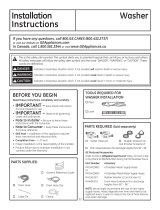
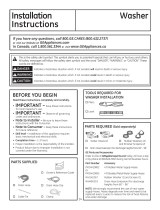
TOOLS REQUIRED
Level
Adjustable wrench
Channel-lock adjustable pliers
Phillips screwdriver
PARTS SUPPLIED
BEFORE YOU BEGIN
Read these instructions completely and carefully.
• IMPORTANT – Save these
instructions for local inspector’s use.
• IMPORTANT – Observe all
governing codes and ordinances.
• Note to Installer – Be sure to leave these
instructions with the Consumer.
• Note to Consumer – Keep these
instructions for future reference.
• Skill level – Installation of this appliance requires
basic mechanical and electrical skills.
• Completion time – 1-3 hours
• Proper installation is the responsibility of the
installer.
• Product failure due to improper installation is not
covered under the Warranty.
Shipping
Bolt Covers
Drain Hose Guide
DO NOT Install the Washer:
1. In an area exposed to dripping water or outside weather
conditions. The ambient temperature should never be
below 60°F (15.6°C) for proper washer operation.
2. In an area where it will come in contact with curtains
or drapes.
3. On carpet. The floor MUST be a hard surface with
DPD[LPXPVORSHRIƎSHUIRRWFPSHU
cm). To make sure the washer does not vibrate or
move, you may have to reinforce the floor.
NOTE:,IIORRULVLQSRRUFRQGLWLRQXVHƎLPSUHJQDWHG
plywood sheet solidly attached to existing floor
covering.
LOCATION OF YOUR WASHER
MOBILE HOME INSTALLATION:
Installation must conform to Standard for Mobile Homes,
ANSI A119.1 and National Mobile Home Construction
and Safety Standards Act of 1974 (PL93-383).
Lock Bar (Retain for
Reversing the Door
Swing option)
Cable Tie
PARTS REQUIRED (Sold separately
or included with the GFW510 model)
Water Hoses (2)
Rubber Washers (2) and
Strainer Screens (2)
GE Appliances Parts and Accessories
Order on-line at GEApplianceparts.com today,
24 hours a day or by phone at 877.959.8688 during
normal business hours. In Canada, visit your local
GE Appliances parts distributor or call 800.661.1616
or GEAppliances.ca/en/products/parts-filters-
accessories.
Part Number Accessory
WX14X10011 6 ft stainless steel washer hoses with
90° elbows; 2-pack
WH1X2267 Rubber Washer (1) and Screen (1)

49-3000217 Rev 2 19
ACCESSORIES:
Order on-line at GEApplianceparts.com, 24 hours a day or
by phone at 877.959.8688 during normal business hours.
Follow the Installation Instructions included in the Kit for all
clearances and installation requirements.
Installation Instructions
WASHER
DIMENSIONS
Side View
32” (81.3 cm)
54-1/2” (138.4 cm)
Models - GFW650, GFW550, GFW510:
Side View
34” (86.4 cm)
56-1/2” (143.8 cm)
Model - GFW850:
28”
(71.2 cm)
*39-3/4”
(101 cm)
Front View
NOTE:
With leveling legs retracted: 39-3/4 (101 cm).
With leveling legs fully extended: 40-5/8 (103.1 cm).
MINIMUM
CLEARANCES
0”
0”
0”
Alcove or Closet
• Rear = 0”*
• Sides = 0”
• 7RS Ǝ
• )URQW Ǝ
0”0”0”
Part Number Accessory
GFP1528SNWW
White Pedestal
GFP1528PNSN
Satin Nickel Pedestal
GFP1528PNRS Royal Sapphire Pedestal
GFP1528PNDG Diamond Gray Pedestal
GFA28KITN Stacking Kit for Dryer over Washer
Stacked:
79-1/2”*
(202 cm)
Pedestal:
55-7/8”*
(141.8 cm)
• Consideration must be given to provide adequate clearance for installation and service.
• Closet doors must be louvered or otherwise ventilated and have at least 60 square inches (387.1 cm
2
) of open area. If the
closet contains both a washer and a dryer, doors must contain a minimum of 120 square inches (774.2 cm
2
) of open area.
* To enable 0” clearance on the back of the washer, you must use 90° elbow hoses. Otherwise you may require some
additional clearance to avoid rubbing of the hoses against the back wall.

20 49-3000217 Rev 2
Installation Instructions
1. Cut and remove all packaging straps.
2. While it is in the carton, carefully lay the washer on its
side. DO NOT lay the washer on its front or back.
3. Turn down the bottom flaps. Remove all base packaging
including the styrofoam base.
4. Carefully return the washer to an upright position and
remove the carton by lifting it upward.
5. Carefully move the washer to within 4 feet (122 cm)
of the final location.
6. Remove the following from the back side of the washer:
4 bolts
4 plastic spacers (including power cord retainers and
rubber grommets)
2 brackets
NOTE: Do NOT remove the screw or clip holding the
hose.
UNPACKING THE WASHER UNPACKING THE WASHER (cont.)
7. Insert shipping bolt hole covers into shipping bolt
holes.
Recycle or destroy the carton and
plastic bags after the washer is
unpacked. Make materials inaccessible to children.
Children might use them for play. Cartons covered
with rugs, bedspreads or plastic sheets can become
airtight chambers causing suffocation.
WARNING
NOTES:
• Failure to remove the shipping braces can cause
the washer to become severely unbalanced.
• IMPORTANT: Save all bolts for future use.
If you must transport the washer at a later date,
you must reinstall the shipping support hardware to
prevent shipping damage. Keep the hardware in the
plastic bag provided.

49-3000217 Rev 2 21
Installation Instructions
ELECTRICAL REQUIREMENTS
CIRCUIT – Individual, properly polarized and grounded
15 or 20 amp circuit breaker or time-delay fuse.
POWER SUPPLY – 2 wire plus ground, 120 Volt, single
phase, 60 Hz, alternating current.
Outlet Receptacle – Properly
grounded 3-prong receptacle to
be located so the power cord is
accessible when the washer is in
an installed position. If a 2-prong
receptacle is present, it is the
owner’s responsibility to have a
licensed electrician replace it with
a properly grounded 3-prong grounding type receptacle.
Washer must be electrically grounded in accordance with
local codes and ordinances, or in the absence of local
codes, with latest edition of the NATIONAL ELECTRICAL
CODE, ANSI/NFPA NO. 70 or CANADIAN ELECTRICAL
CODE, CSA C22.1. Check with a licensed electrician if you
are not sure that the washer is properly grounded.
Ensure proper
ground exists
before use.
Plug into a grounded 3-prong outlet.
DO NOT remove ground prong.
DO NOT use an adapter.
DO NOT use an extension cord.
Failure to follow these instructions can result in death,
fire or electrical shock.
- Electrical Shock Hazard
WARNING
If required by local codes, an external 18 gauge or larger
copper ground wire (not provided) may be added. Attach
to washer cabinet with a #10-16 x
1/2
” sheet metal screw
(available at any hardware store) to rear of washer.
GROUNDING INSTRUCTIONS
This appliance must be grounded. In the event of
malfunction or breakdown, grounding will reduce the risk
of electric shock by providing a path of least resistance
for electric current. This appliance is equipped with a
cord having an equipment- grounding conductor and
a grounding plug. The plug must be plugged into an
appropriate outlet that is properly installed and grounded
in accordance with all local codes and ordinances.
Improper connection of the equipment-
grounding conductor can result in a
risk of electrical shock. Check with a qualified electrician,
or service representative or personnel, if you are in
doubt as to whether the appliance is properly grounded.
DO NOT modify the plug on the power supply cord. If it
will not fit the outlet, have a proper outlet installed by a
qualified electrician.
WARNING
1. Drain capable of eliminating 10
gallons (38 L) per minute.
2. A standpipe diameter of 1-1/4”
(3.18 cm) minimum.
3. The standpipe height above the
floor should be:
Minimum height: 24” (61 cm)
Maximum height: 96” (244 cm)
DRAIN REQUIREMENTS
Hot and cold water faucets MUST be installed within
42 inches (107 cm) of your washer’s water inlet. The
faucets MUST be 3/4” (1.9 cm) garden hose-type so
inlet hoses can be connected. Water pressure MUST be
between 10 and 120 pounds per square inch. Your water
department can advise you of your water pressure. The
hot water temperature should be set to deliver water at
120° to 140°F (48°–60°C) to provide proper Automatic
Temperature Control (ATC) performance.
NOTE: A water softener is recommended to reduce
buildup of scale inside the steam generator if the home
water supply is very hard.
WATER SUPPLY REQUIREMENTS
Disconnect power supply before servicing.
Replace all parts and panels before operating.
Failure to do so can result in death or electrical shock.
WARNING
- Shock Hazard
Certain internal parts are intentionally not grounded
and may present a risk of electric shock only during
servicing.
Service personnel – DO NOT contact the following
parts while the appliance is energized: water valve,
drain pump, NTC, heater, door lock, inverter board,
motor and MC board.
- Electrical Shock Hazard
WARNING
96”
(244 cm)
Max.
24”
(61 cm)
Min.
BACK

22 49-3000217 Rev 2
Installation Instructions
1. Run some water from the hot and cold faucets to
flush the water lines and remove particles that might
clog the inlet hose and water valve screens.
2. Remove the inlet hoses from the packaging (whether
supplied with the washer or sold separately).
3.
(90° elbow end) Ensure there is a
rubber washer in the 90° elbow end of
the HOT and COLD hoses. Reinstall
the rubber washer into the hose fitting
if it has fallen out during shipment.
Carefully connect the inlet hose
marked HOT to the outside “H” outlet of the water valve.
Tighten by hand, then tighten another 2/3 turn with pliers.
Carefully connect the other inlet hose to the inside “C”
outlet of the water valve. Tighten by hand; then tighten
another 2/3 turn with pliers. Do not crossthread or
over-tighten these connections.
4. If inlet hose screen washers are not
already inserted into the inlet hoses,
install them by inserting into the free
ends of the HOT and COLD inlet hoses
with protruded side facing the faucet.
5. Connect the inlet hose ends to the HOT and COLD
water faucets tightly by hand, then tighten another 2/3
turn with pliers. Turn the water on and check for leaks.
6. Carefully move the washer to its final location.
Gently rock the washer into position. It is important
not to damage the rubber leveling legs when moving
your washer to its final location. Damaged legs
can increase washer vibration. It may be helpful to
spray window cleaner on the floor to help move your
washer into its final position.
NOTE: To reduce vibration, ensure that all four rubber
leveling legs are firmly touching the floor. Push and pull
on the back right and then back left of your washer.
NOTE: Do not use the dispenser drawer or door to
lift the washer.
NOTE: If you are installing into a drain pan, you can
use a 24-inch long 2x4 to lever the washer into place.
7. With the washer in its final position,
place a level on top of the washer
(if the washer is installed under
a counter, the washer should not
be able to rock). Adjust the front
leveling legs up or down to ensure
the washer is resting solidly. Turn
the lock nuts on each leg up toward
the base of the washer and snug
with a wrench.
NOTE: Keep the leg extension at
a minimum to prevent excessive
vibration. The farther out the
legs are extended, the more the
washer will vibrate.
If the floor is not level or is damaged,
you may have to extend the rear
leveling legs.
INSTALLING THE WASHER
8. Attach U-shaped hose guide to the end of the drain
hose. Place the hose in a laundry tub or standpipe
and secure it with the cable tie provided in the
enclosure package.
NOTE: Placing the drain hose too far down the drain
pipe can cause a siphoning action. No more than
7 inches of hose should be in the drain pipe. There
must be an air gap around the drain hose. A snug fit
can cause a siphoning action.
9. Plug the power cord into a grounded outlet.
NOTE: Check to be sure the power is off at the
circuit breaker/fuse box before plugging the power
cord into an outlet.
10. Turn on the power at the circuit breaker/fuse box.
11. Read the rest of this Owner’s Manual. It contains
valuable and helpful information that will save you
time and money.
12. Before starting the washer, check to make sure:
Main power is turned on.
The washer is plugged in.
The water faucets are turned on.
The unit is level and all four leveling legs are firmly
on the floor.
The shipping support hardware is removed
and saved.
The drain hose is properly tied up.
There are no leaks at the faucet, drain line
or washer.
13. Run the washer through a complete cycle.
Check for water leaks and proper operation.
14. If your washer does not operate, please review
the Before You Call For Service section before
calling for service.
15. Place these instructions in a location near the
washer for future reference.
INSTALLING THE WASHER (cont.)
If replacement parts are needed for your washer, they can
be ordered in the United States by visiting our Website
at GEApplianceparts.com or by calling GE Appliances
at 877.959.8688. In Canada, visit GEAppliances.ca/en/
products/parts-filters-accessories or call 800.661.1616.
REPLACEMENT PARTS
Video
Scan this code
to watch a video
on Step 7.
Leveling Leg
Cable
Tie
Cable
Tie
Cable Tie

49-3000217 Rev 2 23
Installation Instructions
REVERSING THE DOOR SWING (Optional)
REMOVE THE DOOR HINGE
COVER AND THE DOOR HINGE
• Remove the 3 screws from the hinge cover and
remove the cover.
• Remove the 6 screws from the hinge and remove
the hinge from the door.
2
Hinge Cover
Hinge
Unplug the appliance or turn off the circuit breaker
before servicing. Pressing the Power pad DOES
NOT disconnect power.
WARNING
- Shock Hazard
Certain internal parts are intentionally not grounded
and may present a risk of electric shock only during
servicing.
Service personnel – DO NOT contact the following
parts while the appliance is energized: water valve,
drain pump, NTC, heater, door lock, inverter board,
motor and MC board.
WARNING
REMOVE THE DOOR ASSEMBLY
• Open the washer door.
• While supporting the door, remove the 6 screws
from the hinge in the washer face.
• Lift the door assembly to remove it from the washer
face and set it on a protective surface.
1
Hold the Door and
Remove Hinge Screws
from the Washer
Door and Hinge
Assembly
Phillips-head screwdriver
TOOL YOU WILL NEED
PART SUPPLIED
Lock Bar
IMPORTANT NOTES
• Handle parts carefully to avoid scratching paint.
• Provide a non-scratching work surface for the
door.
• Set screws down by their related parts to avoid
using them in the wrong places.
• Once you begin, do not move the cabinet until
door-swing reversal is completed.
• These instructions are for changing the hinges
from the left side to the right side—if you ever
want to switch them back to the right side, follow
these same instructions and reverse all references
to the left and right.

24 49-3000217 Rev 2
Installation Instructions
REVERSING THE DOOR SWING (Optional)
REMOVE, REVERSE AND
REPLACE THE DOOR STRIKER
• Remove the 2 screws from the striker. Rotate the
striker 180° and reinstall the striker with its screws.
3
REMOVE THE DOOR STRIKER
ASSEMBLY AND REPLACE ON
THE OPPOSITE SIDE
4
• Remove the 2 screws from the striker assembly and
remove the assembly by pulling it toward the center,
pushing it up and pulling it out.
• Rotate the striker assembly and replace it on the
opposite side with its screws.

49-3000217 Rev 2 25
Installation Instructions
REVERSING THE DOOR SWING (Optional)
REPLACE THE DOOR HINGE
AND THE DOOR HINGE COVER
ON THE OPPOSITE SIDE
• Rotate the door hinge and replace it on the opposite
side with its screws.
• Rotate the door hinge cover and replace it on the
opposite side with its screws.
5
REMOVE LOCK ASSEMBLY AND
INSTALL ON OPPOSITE SIDE OF
WASHER
• Remove the 2 screws from the lock cover and
remove it from the washer face.
7
REMOVE THE TERMINAL
HOLDER AND DISCONNECT THE
PIN CONNECTOR FROM WASHER
• Using your
fingers, pry the
terminal holder
from the washer
face.
• Disconnect the
pin connector.
6
Hinge Cover
Hinge
Terminal Holder
Pin Connector
• Insert the provided lock bar into the lock mechanism
in the washer face. Remove the lock assembly by
removing its two screws, using the lock bar to lift it
up to unhook, tilting and pulling it out of the washer
face. Disconnect its pin connector by unsnapping its
locks.
Insert Lock Bar
Remove
Assembly
Pin Connector
Lock
Cover
Hook Window
Hook

26 49-3000217 Rev 2
Installation Instructions
REVERSING THE DOOR SWING (Optional)
REMOVE LOCK ASSEMBLY AND
INSTALL ON OPPOSITE SIDE OF
WASHER (CONTINUED)
• Do NOT rotate lock assembly. Move it to the opposite
side of the washer and connect the pin connector making
sure it is fully snap locked together. Tilt and insert
the lock assembly into the washer face, lift it up and
latch its hook into its window. Replace its screws.
Remove the lock bar from the assembly and retain
for future use.
7
RECONNECT
PIN CONNECTOR
FROM THE WASHER AND REPLACE
THE TERMINAL HOLDER
8
• Reconnect the
pin connector and
press the terminal
holder back into
the washer face on
the opposite side.
Remove lock bar
Replace
Assembly
Pin Connector
• Install the lock cover over the lock assembly, making
sure the locating post fits into the locating hole and
that the lock switch operates freely. Replace its screws.
Pin Connector
Terminal Holder
REPLACE THE DOOR ASSEMBLY
9
• Lift the door assembly into place and secure it onto
the washer face with its 6 screws.
Replace 6 screws
into the hinge and
secure into the
washer face
• Close the washer door.
NOTE: Make sure the door opens and closes
correctly. If not, repeat all steps making sure all
parts and screws are securely seated.
• Connect power cord and turn on the breaker.
• Run the washer through a complete cycle to verify
proper operation.
Hook Window
Hook
Locating Post
Lock Cover
Locating Hole
Lock Switch
/