Crosley YTW4514PNDG User manual

Type
User manual

The Crosley YTW4514PNDG washer is designed to make laundry day a breeze. With a generous 4.5 cubic feet capacity, it can handle even the bulkiest loads, while its 12 wash cycles and 5 temperature settings provide versatility for a variety of fabrics and stains. The washer also features a digital display that keeps you informed of the cycle progress and remaining time, as well as a delay start option that allows you to set the wash cycle to begin at a later time.

The Crosley YTW4514PNDG washer is designed to make laundry day a breeze. With a generous 4.5 cubic feet capacity, it can handle even the bulkiest loads, while its 12 wash cycles and 5 temperature settings provide versatility for a variety of fabrics and stains. The washer also features a digital display that keeps you informed of the cycle progress and remaining time, as well as a delay start option that allows you to set the wash cycle to begin at a later time.

49-3000223 17
Installation
Washer
Instructions
TOOLS REQUIRED FOR
WASHER INSTALLATION
Pliers
Level
PARTS SUPPLIED
PARTS REQUIRED (Sold separately)
Part Number Accessory
PM14X10002 4 ft Rubber Water Supply Hoses
Or
PM14X10005 4 ft Braided Metal Water Supply Hoses
WH1X2267 Rubber Washer (1) and Screen (1)
WH49X301
Drain Hose Extension (For discharge
heights from 60" - 96"
Drain Hose Extension (For discharge heights from 60" - 96"
NOTE: We strongly recommend the use of new water
supply hoses. Hoses degrade over time and need to
be replaced every 5 years to reduce the risk of hose
failures and water damage.
BEFORE YOU BEGIN
Read these instructions completely and carefully.
IMPORTANT – Save these
instructions for local inspector’s use.
IMPORTANT – Observe all
governing codes and ordinances.
Note to Installer – Be sure to leave these
instructions with the Consumer.
Note to Consumer – Keep these
instructions for future reference.
Skill level – Installation of this appliance requires
basic mechanical and electrical skills.
Completion time – 1-3 hours
• Proper installation is the responsibility of the
installer.
• Product failure due to improper installation is not
covered under the Warranty.
Drain Hose
Cable Tie
Clamp
Drain Hose Clip
Owner's Reference Guide
Water Hoses (2) Rubber Washers (2)
and Strainer Screens (2)
18 49-3000223
Installation Instructions
LOCATION OF YOUR WASHER
DO NOT Install the Washer:
1. In an area exposed to dripping water or outside
weather conditions. The ambient temperature should
never be below 60°F (15.6°C) for proper washer
operation.
2. In an area where it will come in contact with curtains or
drapes.
3. On carpet. The floor MUST be a hard surface with a
maximum slope of 1/2″ per foot (1.27 cm per 30 cm).
To make sure the washer does not vibrate or move,
you may have to reinforce the floor.
NOTE: If floor is in poor condition, use 3/4″ impregnated
plywood sheet solidly attached to existing floor covering.
IMPORTANT: Minimum Installation Clearances
- Alcove or Closet
If your washer is approved for installation in an alcove or
closet, there will be a label on the back of the machine
describing requirements.
Minimum clearance between washer and adjacent walls
or other surfaces: 0" either side, 2" front, 3" rear.
Vertical space from floor to overhead shelving, cabinets,
ceiling, etc. = 60".
Closet doors must be louvered or otherwise ventilated
and have at least 60 square inches of open area. If the
closet contains both a washer and a dryer, doors must
contain a minimum of 120 square inches of open area.
NOTE: The clearances stated on this label are minimums.
Consideration must be given to providing adequate
clearances for installing and servicing.
After the machine is in the home, remove outside
packing material/carton from washer.
Remove bag (containing clamp, cable tie and drain
hose clip), drain hose and Owner's Reference Guide
from tub.
NOTE: Leave foam shipping material inside tub
opening to hold tub in place during the rest of
installation.
1 UNPACKING THE WASHER
WATER SUPPLY REQUIREMENTS
WATER SUPPLY LINES - Purge Hot and Cold water supply lines for 30 seconds prior to installation of hoses and washing
machine. Ensure inlet hose screens are also clean and free of debris.
WATER PRESSURE - Must be 20 psi minimum to 120 psi maximum.
WATER TEMPERATURE - Household water heater should be set to deliver water at 120° to 150°F (50° to 66°C) TO THE
WASHER when hot wash is selected.
SHUTOFF VALVES - Both hot and cold shutoff valves (faucets) should be supplied.
DRAIN - Water should be drained into standpipe. Discharge height MUST NOT BE LESS THAN 30 INCHES, and no
more than 8 feet above the base of the washer. Standpipe must be 1-1/2 inches minimum inside diameter and must
be open to atmosphere.
Bag
Owner's Reference Guide
Leave foam shipping
material inside tub
Drain hose
Remove base from unit by placing foot on side of base
and tipping unit back on corner post. Remove base and
bring the washer back upright.
2 REMOVE THE BASE
Certain internal parts are intentionally not grounded
and may present a risk of electric shock only during
servicing.
Service personnel – DO NOT contact the following
parts while the appliance is energized: Drive Motor,
Lid Lock, Water Valves, Drain Pump and Recirculation
Pump.
- Electrical Shock Hazard
WARNING
49-3000223 19
Installation Instructions
5 CONNECT WATER HOSES TO
OUTLET VALVES
Determine which is HOT water line before attaching
water hoses to faucets. Traditionally, HOT faucet is on
left.
(If screen washers are not installed) With protruding
part of screen toward you, install strainer screen/rubber
washer into each of the free ends of two water hoses.
Connect hot water hose to hot water
outlet valve of your home. Hand
tighten and use pliers to tighten
hoses between 1/4 and 1/2 turn
beyond hand-tight. Open hot water
valve.
Connect cold water hose to cold
water outlet valve of your home.
Hand tighten and use pliers to
tighten hoses between 1/4 and 1/2
turn beyond hand-tight. Open cold water valve.
Check for leaks and drips at the hose couplings. Tighten
as necessary.
Unplug electrical cord before installing water hoses. If
not installed, install rubber washer in one end of hot
water hose. Thread hot water hose onto connection
labeled H at top rear of washer. Hand tighten and use
pliers to tighten hoses between 1/8 and 1/4 turn beyond
hand-tight.
If not installed, install rubber washer in one end of cold
water hose C. Thread cold water hose onto connection
labeled C at top rear of washer. Hand tighten and use
pliers to tighten hoses between 1/8 and 1/4 turn beyond
hand-tight.
Move washer as close to final location as possible,
leaving room for you to make water, drain, and electrical
connections to your home.
4 CONNECT WATER HOSES TO
WASHER
Rubber
washer
Rubber
washer
Connect drain hose to drain port on back of washer. Open
clamp with pliers and slide onto hose end. Holding clamp
open, push hose end onto drain port until fully seated.
Release clamp between locating ribs on hose end. Outlet
of hose end should be oriented vertically.
3 CONNECT DRAIN HOSE TO
WASHER
Drain
hose
Drain
port
Drain
end
Clamp
Remove the cap from the drain port, if present, before
installing the drain hose.
Cap
Port
Washer Back
20 49-3000223
Installation Instructions
6 CONNECT TO DRAIN
Install drain hose clip on
rear panel of washer.
Route drain hose through
clip and insert free end
into drain opening of your
home.
If water valves and drain are built into wall, fasten drain
hose to one of the water hoses with cable tie provided.
If your drain is a standpipe, fasten drain hose to
standpipe with cable tie provided.
NOTE: If longer
drain hose is
required, order
drain hose extension
kit, part number
WH49X301. Connect
additional drain
hose (contained in
kit) to original hose
with hose clamp
(contained in kit).
6 CONNECT TO DRAIN (Continued)
NOTE: Placing the drain hose too far down the drain
pipe can cause a siphoning action. No more than 5" of
hose should be in the drain pipe. There must be an air
gap around the drain hose. A snug fit can also cause a
siphoning action.
NOTE: Placing the drain hose too far down the drain
pipe can cause a siphoning action. No more than 5" of
hose should be in the drain pipe. There must be an air
gap around the drain hose. A snug fit can also cause a
siphoning action.
If drain discharge height does not meet 30"
minimum height requirement, end of drain hose must
be secured in drain opening of home by installer and
have an air gap around hose to prevent siphoning.
Drain
hose
clip
Drain
hose Washer
back
Wall
5" Max.
insertion
into
drain
30"
Min.
Drain
hose Cable tie
Washer
back
Drain
hose
clip
30"
Min.
5" Max.
insertion
into
drain
Drain
hose
Cable
tie
Standpipe
Washer
back
Drain
hose
clip
Less than
30"
Drain
hose
Washer
back
Drain
hose
clip
NOTE: Placing the drain hose too far down the drain
pipe can cause a siphoning action. No more than 5" of
hose should be in the drain pipe. There must be an air
gap around the drain hose. A snug fit can also cause a
siphoning action.
49-3000223 21
ELECTRICAL REQUIREMENTS
CIRCUIT – Individual, properly polarized and grounded
15 or 20 amp circuit breaker or time-delay fuse.
POWER SUPPLY – 2 wire plus ground, 120 Volt, single
phase, 60 Hz, alternating current.
Outlet Receptacle – Properly grounded 3-prong
receptacle to be located so
the power cord is accessible
when the washer is in an
installed position. If a 2-prong
receptacle is present, it is the
owner’s responsibility to have
a licensed electrician replace it
with a properly grounded 3-prong
grounding type receptacle.
Washer must be electrically grounded in accordance with
local codes and ordinances, or in the absence of local
codes, with latest edition of the NATIONAL ELECTRICAL
CODE, ANSI/NFPA NO. 70 or CANADIAN ELECTRICAL
CODE, CSA C22.1. Check with a licensed electrician if you
are not sure that the washer is properly grounded.
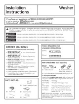
If required by local codes, an external 18 gauge or
larger copper ground wire (not provided) may be
added. Attach to washer cabinet with a #10-16 x
1/2
sheet metal screw (available at any hardware store) to
rear of washer as illustrated.
Mobile Home Installation:
Installation must conform to Standard for Mobile Homes,
ANSI A119.1 and National Mobile Home Construction
and Safety Standards Act of 1974 (PL93-383).
GROUNDING INSTRUCTIONS
This appliance must be grounded. In the event of
malfunction or breakdown, grounding will reduce the
risk of electric shock by providing a path of least
resistance for electric current. This appliance is
equipped with a cord having an equipment- grounding
conductor and a grounding plug. The plug must be
plugged into an appropriate outlet that is properly
installed and grounded in accordance with all local
codes and ordinances.
Improper connection of the equipment-
grounding conductor can result in a
risk of electrical shock. Check with a qualified electrician,
or service representative or personnel, if you are in
doubt as to whether the appliance is properly grounded.
DO NOT modify the plug on the power supply cord. If it
will not fit the outlet, have a proper outlet installed by a
qualified electrician.
Attach ground
wire and ground
screw (obtain
locally) Washer
back
Insert plug of electrical cord into a 115V, 15- or 20-amp
wall
receptacle. Move washer into final position. Place level on
flat top side edges of washer. Adjust all four leveling legs until
washer is level left-to-right and front-to-back. Remove level.
Open tub lid. Remove and discard tub shipping material (see
Step 1).
Remove plastic protector sheet from control panel face.
7 CONNECT POWER AND INSTALL
Level
Ensure proper
ground exists
before use.
Plug into a grounded 3-prong outlet.
DO NOT remove ground prong.
DO NOT use an adapter.
DO NOT use an extension cord.
Failure to follow these instructions can result in death,
fire or electrical shock.
- Electrical Shock Hazard
WARNING
WARNING
Installation Instructions
Before starting the washer, check to make sure:
Main power is turned on.
The washer is plugged in.
The water faucets are turned on.
The unit is level and all four leveling legs are firmly
on the floor.
The shipping foam and cardboard are removed.
The drain hose is properly tied up.
There are no leaks at the faucet, drain line
or washer.
Remove the cap from the drain port, if present,
before installing the drain hose.
Run the washer through a complete cycle.
Check for water leaks and proper operation.
Place these instructions in a location near the washer
for future reference.
FINAL CHECKLIST
  • Page 1 1
  • Page 2 2
  • Page 3 3
  • Page 4 4
  • Page 5 5

Crosley YTW4514PNDG User manual

Type
User manual

The Crosley YTW4514PNDG washer is designed to make laundry day a breeze. With a generous 4.5 cubic feet capacity, it can handle even the bulkiest loads, while its 12 wash cycles and 5 temperature settings provide versatility for a variety of fabrics and stains. The washer also features a digital display that keeps you informed of the cycle progress and remaining time, as well as a delay start option that allows you to set the wash cycle to begin at a later time.

Ask a question and I''ll find the answer in the document

Finding information in a document is now easier with AI