Page is loading ...

IMS01N13-E2
SRX
PLC/Host Communication
Instruction Manual
RKC INSTRUMENT INC.
®
Module Type Controller

All Rights Reserved, Copyright 2004, RKC INSTRUMENT INC.
Modbus is a registered trademark of Schneider Electric.
The name of each programmable controller (PLC) means the products of each manufacturer.
Company names and product names used in this manual are the trademarks or registered trademarks of
the respective companies.

IMS01N13-E2
i-1
Thank you for purchasing this RKC instrument. In order to achieve maximum performance and ensure
proper operation of your new instrument, carefully read all the instructions in this manual. Please
place this manual in a convenient location for easy reference.
SYMBOLS
: This mark indicates important information on installation, handling and operating
procedures.
: This mark indicates supplemental information on installation, handling and
operating procedures.
: This mark indicates where additional information may be located.
An external protection device must be installed if failure of this instrument
could result in damage to the instrument, equipment or injury to personnel.
All wiring must be completed before power is turned on to prevent electric
shock, fire or damage to instrument and equipment.
This instrument must be used in accordance with the specifications to
prevent fire or damage to instrument and equipment.
This instrument is not intended for use in locations subject to flammable or
explosive gases.
Do not touch high-voltage connections such as power supply terminals, etc.
to avoid electric shock.
RKC is not responsible if this instrument is repaired, modified or
disassembled by other than factory-approved personnel. Malfunction can
occur and warranty is void under these conditions.
CAUTION
: This mark indicates precautions that must be taken if there is danger of electric
shock, fire, etc., which could result in loss of life or injury.
: This mark indicates that if these precautions and operating procedures are not
taken, damage to the instrument may result.
: This mark indicates that all precautions should be taken for safe usage.
WARNING
!
WARNING
!

IMS01N13-E2
i-2
This is a Class A instrument. In a domestic environment, this instrument may cause radio
interference, in which case the user may be required to take adequate measures.
This instrument is protected from electric shock by reinforced insulation. Provide
reinforced insulation between the wire for the input signal and the wires for instrument
power supply, source of power and loads.
Be sure to provide an appropriate surge control circuit respectively for the following:
- If input/output or signal lines within the building are longer than 30 meters.
- If input/output or signal lines leave the building, regardless the length.
This instrument is designed for installation in an enclosed instrumentation panel. All
high-voltage connections such as power supply terminals must be enclosed in the
instrumentation panel to avoid electric shock by operating personnel.
All precautions described in this manual should be taken to avoid damage to the
instrument or equipment.
All wiring must be in accordance with local codes and regulations.
All wiring must be completed before power is turned on to prevent electric shock,
instrument failure, or incorrect action.
The power must be turned off before repairing work for input break and output failure
including replacement of sensor, contactor or SSR, and all wiring must be completed
before power is turned on again.
To prevent instrument damage or failure, protect the power line and the input/output lines
from high currents with a protection device such as fuse, circuit breaker, etc.
Prevent metal fragments or lead wire scraps from falling inside instrument case to avoid
electric shock, fire or malfunction.
Tighten each terminal screw to the specified torque found in the manual to avoid electric
shock, fire or malfunction.
For proper operation of this instrument, provide adequate ventilation for heat dispensation.
Do not connect wires to unused terminals as this will interfere with proper operation of the
instrument.
Turn off the power supply before cleaning the instrument.
Do not use a volatile solvent such as paint thinner to clean the instrument. Deformation or
discoloration will occur. Use a soft, dry cloth to remove stains from the instrument.
To avoid damage to instrument display, do not rub with an abrasive material or push front
panel with a hard object.
Do not connect modular connectors to telephone line.
NOTICE
This manual assumes that the reader has a fundamental knowledge of the principles of electricity,
process control, computer technology and communications.
The figures, diagrams and numeric values used in this manual are only for purpose of illustration.
RKC is not responsible for any damage or injury that is caused as a result of using this instrument,
instrument failure or indirect damage.
Periodic maintenance is required for safe and proper operation of this instrument. Some
components have a limited service life, or characteristics that change over time.
Every effort has been made to ensure accuracy of all information contained herein. RKC makes no
warranty expressed or implied, with respect to the accuracy of the information. The information in
this manual is subject to change without prior notice.
No portion of this document may be reprinted, modified, copied, transmitted, digitized, stored,
processed or retrieved through any mechanical, electronic, optical or other means without prior
written approval from RKC.
CAUTION

IMS01N13-E2 i-3
CONTENTS
Page
1. OUTLINE .............................................................................. 1
1.1 SRX Unit Configuration ................................................................................... 2
1.1.1 When one SRX unit is connected ........................................................................ 2
1.1.2 When two or more SRX units are connected ....................................................... 3
2. COMMUNICATION SPECIFICATIONS ................................ 5
3. SETTING PROCEDURE TO OPERATION .......................... 8
3.1 When Use PLC Communication and Host Communication ............................. 8
3.2 Only When Use PLC Communication ............................................................ 11
3.3 Only When Use Host Communication ........................................................... 14
4. COMMUNICATION SETTING ............................................ 16
4.1 Communication Port Assignments ................................................................. 16
4.2 Module Address Setting ................................................................................ 21
4.3 Unit Address Setting ...................................................................................... 23
4.4 Communication Setting Switch ...................................................................... 24
4.5 Internal Data Bus Termination Resistor Setting ............................................. 29
4.6 Initializing Internal Communication ................................................................ 31
5. PLC COMMUNICATION ..................................................... 34
5.1 MITSUBISHI MELSEC series ........................................................................ 34
5.1.1 Outline ................................................................................................................ 34
5.1.2 Wiring ................................................................................................................. 36
5.1.3 PLC communication environment setting ........................................................... 42
5.1.4 Setting on the PLC (Computer link module) ....................................................... 52
5.2 Data Transfer ................................................................................................. 53
5.2.1 Fixed data transfer type ..................................................................................... 53
5.2.2 Specified data transfer type ............................................................................... 58
5.3 PLC Communication Data Map ..................................................................... 62
5.4 Usage Example ............................................................................................. 74
5.4.1 Handling procedures .......................................................................................... 74
5.4.2 System configuration .......................................................................................... 75

IMS01N13-E2
i-4
Page
5.4.3 Connection with PLC .......................................................................................... 76
5.4.4 SRX setting ........................................................................................................ 77
5.4.5 PLC setting ......................................................................................................... 85
5.4.6 Initial setting ....................................................................................................... 87
5.4.7 Data setting ........................................................................................................ 88
6. HOST COMMUNICATION .................................................. 95
6.1 Outline ........................................................................................................... 95
6.2 Wiring ............................................................................................................ 96
6.3 Communication Requirements .................................................................... 102
6.4 RKC Communication Protocol ..................................................................... 103
6.4.1 Polling .............................................................................................................. 103
6.4.2 Selecting .......................................................................................................... 109
6.4.3 Communication data structure ......................................................................... 113
6.4.4 Communication identifier list of TIO module .................................................... 116
6.4.5 Communication identifier list of DI module ....................................................... 128
6.4.6 Communication identifier list of DO module ..................................................... 131
6.5 Modbus Communication Protocol ................................................................ 136
6.5.1 Message format ............................................................................................... 136
6.5.2 Function code ................................................................................................... 137
6.5.3 Communication mode ...................................................................................... 137
6.5.4 Slave response ................................................................................................ 138
6.5.5 Calculating CRC-16 ......................................................................................... 139
6.5.6 Message format ............................................................................................... 142
6.5.7 Data configuration ............................................................................................ 146
6.5.8 Data map of TIO module .................................................................................. 151
6.5.9 Data map of DI module .................................................................................... 180
6.5.10 Data map of DO module ................................................................................ 183
7. TROUBLESHOOTING ...................................................... 187

IMS01N13-E2
i-5
Page
APPENDIX A. HARDWARE ................................................ 193
A.1 Terminal Configuration ................................................................................ 193
A.2 Various Setting Change by the Switch ........................................................ 194
A.3 Indication Lamp ........................................................................................... 196
A.4 Product Specifications ................................................................................. 197
APPENDIX B. ASCII 7-BIT CODE TABLE ......................... 210

i-6 IMS01N13-E2
MEMO

IMS01N13-E2 1
1. OUTLINE
This manual describes communication with the programmable controller (hereafter called the PLC)
and host computer when the temperature control module for PLC communication X-TIO-R for the
module type controller SRX is used.
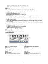
Three communication ports (COM. PORT1 to 3) of the X-TIO-R module can be selected from
among the following four assignments. (The communication specification of COM. PORT2 is the
same as that of COM. PORT3.)
Assignment 1 Assignment 2 Assignment 3 Assignment 4
COM. PORT1
Host
communication 1
PLC
communication
Host
communication 1
Host
communication 2
COM. PORT2/
COM. PORT3
PLC
communication
Host
communication 1
Host
communication 2
Host
communication 1
For host communication 1 or 2, its data bit configuration, communication speed and
communication protocol can be independently set.
In addition to the three communication ports (COM. PORT1 to 3) of the X-TIO-R module, it is also
possible to conduct host communication using the host communication terminal.
Up to 29 modules that is the temperature control module (X-TIO-A/B), the digital input (DI) module
and the digital output (DO) module, can be connected to one X-TIO-R module.
For PLC communication, up to four X-TIO-R modules can be multi-drop connected to one PLC
communication port. Therefore, temperature control of up to 240 channels per one PLC
communication port can be performed. (For using the COM. PORT2 and COM. PORT3)
For host communication, up to 16 X-TIO-R modules can be multi-drop connected to one host
communication port. Therefore, temperature control of up to 960 channels per one host
communication port can be performed. (For using the COM. PORT2 and COM. PORT3)
For specification, parts description and wiring of the X-TIO-R module, see Temperature
Control Module for PLC Communication X-TIO-R Instruction Manual (IMS01N12-E).
In addition, for host communication using host communication terminals, see Module Type
Controller SRX Communication Instruction Manual (IMS01N01-E).
COM. PORT3
X-TIO-R module
COM. PORT2
COM. PORT1
*
As COM. PORT2/COM. PORT3
are internally connected, multi-drop
connection is easily made if either
of these ports is used.
*
*
Host communication
terminal
5
4
3
2
1
0
9
8
7
6
5 5
4
3
2
1
0
9
8
7
6
5
FA IL/ R U
N
RX/TX
EV E N T 1
EV E N T 2
EV E N T 3
EV T N T 4
Communication port of X-TIO-R module

1. OUTLINE
IMS01N13-E2
2
1.1 SRX Unit Configuration
One SRX unit consists of one X-TIO-R module and several other temperature control
modules.
1.1.1 When one SRX unit is connected
Up to 29 modules that is the temperature control module (X-TIO-A/B), the digital input (DI) module
and the digital output (DO) module, can be connected to one X-TIO-R module with the SRX unit.
(Common to PLC communication and host communication)
As the number of temperature control channels per module is 2, the maximum number of
temperature control channels per unit becomes 60 when the SRX unit is configured with only a
temperature control module. (Including the temperature control channels of the X-TIO-R module.)
[Example] When each communication port of the X-TIO-R module is assigned as follows.
COM.PORT1: Host communication 1 (RS-422A or RS-232C)
COM.PORT2/3: PLC communication (RS-422A)
For the communication port assignment, see 4.1 Communication Port Assignments (P. 16).
SRX unit (Unit address: 0)
X-TIO-R module
Module
address
Up to 29 temperature control modules can be connected to one X-TIO-R module
Number of temperature control channel: 60 CH max.
Temperature control module
[extension type] X-TIO-B
0
1 229
PLC
RS-422A
PLC
communication
Host
Computer
RS-422A or
RS-232C
Host
communication 1

1. OUTLINE
IMS01N13-E2
3
1.1.2 When two or more SRX units are connected
Multi-drop connection by PLC communication
For PLC communication, up to four X-TIO-R modules (i.e. four SRX units) can be multi-drop
connected to one PLC communication port.
In addition, as up to 29 temperature control modules can be connected to one X-TIO-R module, it is
possible to perform temperature control of up to 240 channels (60 channels 4 SRX units) if the SRX
unit is configured by using temperature control modules only. (Including the temperature control
channels of the X-TIO-R module.)
[Example] When each communication port of the X-TIO-R module is assigned as follows.
COM.PORT1: Host communication 1 (RS-422A or RS-232C)
COM.PORT2/3: PLC communication (RS-422A) [Multi-drop connection]
For the communication port assignment, see 4.1 Communication Port Assignments (P. 16).
RS-422A
PLC
communication
SRX unit 1 (Unit address: 0)
0
1 2 29
PLC
RS-422A
X
-TIO-R
module
Module
address
Up to four X-TIO-R modules can be
multi-drop connected to one PLC
communication port.
Number of temperature control channel:
240 CH max.
Temperature control module
[extension type] X-TIO-B
PLC
communication
SRX unit 4 (Unit address: 3)
0
1 2 29
SRX unit 3 (Unit address: 2)
0
1 2 29
SRX unit 2 (Unit address: 1)
0
1 2 29
RS-422A
PLC
communication
RS-422A
PLC
communication
Host
Computer
RS-422A or
RS-232C
Host communication 1

1. OUTLINE
IMS01N13-E2
4
Multi-drop connection by host communication
For host communication, up to 16 X-TIO-R modules (i.e. 16 SRX units) can be multi-drop connected
to one communication port of host computer or operation panel.
In addition, as up to 29 temperature control modules can be connected to one X-TIO-R module, it is
possible to perform temperature control of up to 960 channels (60 channels 16 SRX units) if the
SRX unit is configured by using temperature control modules only. (Including the temperature control
channels of the X-TIO-R module.)
[Example] When each communication port of the X-TIO-R module is assigned as follows.
COM.PORT1: Host communication 1 (RS-422A or RS-232C)
COM.PORT2/3: Host communication 2 (RS-422A) [Multi-drop connection]
When in the above figure, the host computer connected to COM. PORT1 can communicate
only with SRX unit 1.
When connecting the operation panel to the SRX unit, please contact RKC sales office or the
agent.
For multi-drop connection using COM. PORT1, see 5.1.2 Wiring (P. 36) [MITSUBISHI
PLC], or 6.2 Wiring (P. 96) [host communication].
For the communication port assignment, see 4.1 Communication Port Assignments (P. 16).
RS-422A
SRX unit 1 (Unit address: 0)
0
1 2 29
Host
Computer
RS-422A
RS-422A or
RS-232C
Up to 16 X-TIO-R modules can
be multi-drop connected to one
communication port of host
computer or operation panel.
Number of temperature control channel:
960 CH max.
Host
communication 1
0
1 2 29
Operation panel
Host
communication 2
Host
communication 2
SRX unit 16 (Unit address: F)
X
-TIO-R
module
Temperature control module
[extension type] X-TIO-B
Module
address
X
-TIO-R
module
Temperature control module
[extension type] X-TIO-B
Module
address

IMS01N13-E2 5
2. COMMUNICATION SPECIFICATIONS
PLC communication
Interface: Based on RS-422A, EIA standard
Based on RS-232C, EIA standard
COM. PORT1: Specify when ordering
COM. PORT2/COM. PORT3: RS-422A (fixed)
Connection method: RS-422A: 4-wire system, full-duplex multi-drop connection
RS-232C: Point-to-point connection
Synchronous method: Start/stop synchronous type
Communication speed: 9600 bps, 19200 bps, 38400 bps
Communication speed can be selected with switch
Data bit configuration: Start bit: 1
Data bit: 7 or 8
Parity bit: Without, Odd or Even
Without for 8 data bits
Stop bit: 1 or 2
Data bit configuration can be selected with switch
Protocol: MITSUBISHI MELSEC series special protocol
ACPU common command (A series, FX2N, FX2NCseries)
AnA/AnUCPU common command (AnA/QnA series, Q series)
The protocol can be selected with switch
Maximum connections: Four modules (X-TIO-R) per communication port of PLC
[Temperature control channel: 240 CH max.]

2. COMMUNICATION SPECIFICATIONS
IMS01N13-E2
6
Host communication (modular connector side)
Interface: Based on RS-422A, EIA standard
Based on RS-232C, EIA standard
COM. PORT1: Specify when ordering
COM. PORT2/COM. PORT3: RS-422A (fixed)
Connection method: RS-422A: 4-wire system, full-duplex multi-drop connection
RS-232C: Point-to-point connection
Synchronous method: Start/stop synchronous type
Communication speed: 2400 bps, 9600 bps, 19200 bps, 38400 bps
Communication speed can be selected with switch
Data bit configuration: Start bit: 1
Data bit: 7 or 8 (RKC communication)
8 (Modbus)
Parity bit: Without, Odd or Even
Without for 8 data bits
Stop bit: 1 or 2
Data bit configuration can be selected with switch
Protocol: RKC communication
Based on ANSI X3.28 subcategory 2.5 B1
Polling/selecting type
Error control: Vertical parity (with parity bit selected)
Horizontal parity (BCC check)
Data types: ASCII 7-bit code
Modbus
Signal transmission mode: Remote Terminal Unit (RTU) mode
Function codes: 03H Read holding registers
06H Preset single register
08H Diagnostics (loopback test)
10H Preset multiple registers
Error check method: CRC-16
Error codes: 1: Function code error
(An unsupported function code was specified)
2: When the mismatched address is specified.
3: When the data written exceeds the setting range.
When the specified number of data items in the
query message exceeds the maximum number
(1 to 125) of data items available
RKC communication or Modbus protocol can be selected with switch
Maximum connections: RS-422A: 16 modules (X-TIO-R) per communication port of host
computer [Temperature control channel: 960 CH max.]
RS-232C: One module (X-TIO-R) per communication port of host
computer [Temperature control channel: 60 CH max.]

2. COMMUNICATION SPECIFICATIONS
IMS01N13-E2
7
Host communication (host communication terminal side)
Interface: Based on RS-485, EIA standard
Connection method: 2-wire system, half-duplex multi-drop connection
Synchronous method: Start/stop synchronous type
Communication speed: 2400 bps, 9600 bps, 19200 bps, 38400 bps
Communication speed can be selected with switch
Data bit configuration: Start bit: 1
Data bit: 7 or 8 (RKC communication)
8 (Modbus)
Parity bit: Without, Odd or Even
Without for 8 data bits
Stop bit: 1 or 2
Data bit configuration can be selected with switch
Protocol: RKC communication
Based on ANSI X3.28 subcategory 2.5 B1
Polling/selecting type
Error control: Vertical parity (with parity bit selected)
Horizontal parity (BCC check)
Data types: ASCII 7-bit code
Modbus
Signal transmission mode: Remote Terminal Unit (RTU) mode
Function codes: 03H Read holding registers
06H Preset single register
08H Diagnostics (loopback test)
10H Preset multiple registers
Error check method: CRC-16
Error codes: 1: Function code error
(An unsupported function code was specified)
2: When the mismatched address is specified.
3: When the data written exceeds the setting range.
When the specified number of data items in the
query message exceeds the maximum number (1
to 125) of data items available
RKC communication or Modbus protocol can be selected with switch
Maximum connections: 31 modules maximum including a host computer
(Up to 29 modules can be connected to one X-TIO-R module)

8 IMS01N13-E2
3. SETTING PROCEDURE TO OPERATION
3.1 When Use PLC Communication and Host Communication
Conduct necessary setting before operation according to the procedure described below.
Set the communication speed, data bit configuration, protocol, and communication
port.
See 4.1 Communication Port Assignments (P. 16) and 4.4 Communication
Setting Switch (P. 24).
PLC communication setting
Address setting
Set the SRX unit address and module address
See 4.2 Module Address Setting (P. 21) and 4.3 Unit Address Setting (P. 23).
Connection of
communication line
Connect PLC to SRX. For host communication, connect to host computer.
See 5.1.2 Wiring (P. 36) [MITSUBISHI PLC], or 6.2 Wiring (P. 96) [Hos
t
communication].
Host communication setting
Set the communication speed, data bit configuration and protocol.
See 4.4 Communication Setting Switch (P. 24).
Wiring of SRX
Wire a power supply and input/output of SRX.
For the X-TIO-R module, see APPENDIX A.1 Terminal Configuration (P. 193).
For other modules, see the Instruction Manual of each module.
A
Set the internal data bus termination resistor to SRX.
See 4.5 Internal Data Bus Termination Resistor Setting (P. 29).
Internal data bus
termination resistor setting

3. SETTING PROCEDURE TO OPERATION
IMS01N13-E2
9
When turn on the power supply of SRX, PLC and host computer, the SR
X
performs as follows.
1. The X-TIO-R module starts collecting data on each module connected from the
time when the power is turned on.
2. The RUN lamp corresponding to indication lamp 2 flashed at very shor
t
intervals.
3.
A
fter data collection is finished and PLC communication becomes enabled *,
the RUN lamp keeps lighting and as a result “SRX communication state” and
“Control word 2” is set to 1.
* Time required for enabling PLC communication is about 15 seconds.
Power ON
To prevent malfunction, always turn on the power of the SRX last. In
addition, if there are two or more SRX units in PLC communication,
always turn on the power of the master unit last.
PLC communication
environment settin
g
For PLC communication, set a necessary item.
See 5.1.3 PLC communication environment setting (P. 42) [MITSUBISHI PLC].
Set initial setting data and the operation data that setting is impossible in PLC
communication.
See 6.4 RKC Communication Protocol (P. 103) or 6.5 Modbus Communication
Protocol (P. 136).
Setting of SRX setting data
by host communication
Power ON again
Turn off the power of the SRX, PLC and host computer once, and then turn it on
again.
A
Follow the caution of “Power ON.”
The X-TIO-R module recognizes modules connected within the same unit b
y
initializing internal communication.
See 4.6 Initializing Internal Communication (P. 31).
Initializing internal
communication
Follow the caution of “Power ON.”
B

3. SETTING PROCEDURE TO OPERATION
IMS01N13-E2
10
Before changing the SRX data from PLC, always read it into the PLC once.
The initial setting must always conduct. If each set value of SRX is chan
g
ed
from the PLC without setting the initial values, it is re-written to 0 with
each set value of the PLC at that time set to 0.
See 5.2 Data Transfer (P. 53) or 5.4 Usage Example (P. 74).
PLC setting
PLC communication
initial setting
Data setting
by PLC communication
Change each SRX set value data from the PLC.
See 5.3. PLC Communication Data Map (P. 62) or 5.4 Usage Example (P. 74).
Operation start
Set the PLC side.
See 5.1.4 Setting on the PLC (Computer link module) (P. 52) or 5.4 Usa
g
e
Example (P. 74).
B

3. SETTING PROCEDURE TO OPERATION
IMS01N13-E2
11
3.2 Only When Use PLC Communication
Conduct necessary setting before operation according to the procedure described below.
As some items can be set only via host communication, carefully check them and then
conduct host communication, if necessary.
For details of items which can be set only via host communication, see as follows.
6.4.4 Communication identifier list of TIO module (P. 116)
6.4.5 Communication identifier list of DI module (P. 128)
6.4.6 Communication identifier list of DO module (P. 131)
6.5.8 Data map of TIO module (P. 151)
6.5.9 Data map of DI module (P. 180)
6.5.10 Data map of DO module (P. 183)
Set the communication speed, data bit configuration, protocol, and communication
port.
See 4.1 Communication Port Assignments (P. 16) and 4.4 Communication
Setting Switch (P. 24).
PLC communication setting
Address setting
Set the unit address and module address
See 4.2 Module Address Setting (P. 21) and 4.3 Unit Address Setting (P. 23).
PLC communication
environment setting
For PLC communication, set a necessary item.
Set by switch as no host computer is used.
See 5.1.3 PLC communication environment setting (P. 42) [MITSUBISHI PLC].
Wiring of SRX
Wire a power supply and input/output of SRX.
For the X-TIO-R module, see APPENDIX A.1 Terminal Configuration (P. 193).
For other modules, see the Instruction Manual of each module.
C
Set the internal data bus termination resistor to SRX.
See 4.5 Internal Data Bus Termination Resistor Setting (P. 29).
Internal data bus
termination resistor setting

3. SETTING PROCEDURE TO OPERATION
IMS01N13-E2
12
When turn on the power supply of SRX and PLC, the SRX performs as follows.
1. The X-TIO-R module starts collecting data on each module connected from the
time when the power is turned on.
2. The RUN lamp corresponding to indication lamp 2 flashed at very short
intervals.
3. After data collection is finished and PLC communication becomes enabled *,
the RUN lamp keeps lighting and as a result “SRX communication state” and
“Control word 2” is set to 1.
* Time required for enabling PLC communication is about 15 seconds.
Connection of
communication line
Connect PLC to SRX.
See 5.1.2 Wiring (P. 36) [MITSUBISHI PLC].
Power ON
To prevent malfunction, alwa
y
s turn on the power of the SRX last. In
addition, if there are two or more SRX units in PLC communication, alwa
y
s
turn on the power of the master unit last.
C
PLC setting
Set the PLC side.
See 5.1.4 Setting on the PLC (Computer link module) (P. 52), or 5.4 Usa
g
e
Example (P. 74).
The X-TIO-R module recognizes modules connected within the same unit b
y
initializing internal communication.
See 4.6 Initializing Internal Communication (P. 31).
Initializing internal
communication
Follow the caution of “Power ON.”
D
/