1. PRODUCT DESCRIPTION
All FireHawk smoke and heat alarms are approved to the most recent and
rigorous standards. The photoelectric smoke alarms with their new High-
Performance X-Profile sensing chamber are approved to EN14604: 2005 and
are particularly sensitive to slow smouldering fires typically originating in
living rooms, bedrooms and hallways, whilst being highly resistant to nuisance
alarms.
The FHN250BB alarms are guaranteed for 6 years and the FHN250RB
for 10 years. However, their lives can be significantly reduced by adverse
environments, incorrect location and a failure to regularly clean and maintain
them according to the following instructions. Incorrect location and a lack of
reasonable care may also cause them to malfunction and will invalidate the
warranty.
Product Features
• All models are supplied with a back-up power source. The FHN250RB has
a lifetime rechargeable lithium battery that is automatically switched on as
the detector is installed onto its mounting plate and automatically switched
off when detector is removed. The FHN250BB has 3 x AAA replaceable
alkaline batteries.
• Alarm Silence - Silence your smoke alarm by momentarily pressing the
test button. Ideal in non-emergency situations when nuisance alarms may
have been created, for example, by steam. The red light flashes every 8
seconds to remind you that the smoke alarm has been silenced and will
automatically reset to standby mode in 10 minutes.
• Bespoke software maximizes detection ability and false alarm rejection via
the new Dust Compensation feature.
• A permanent green LED indicates mains power is connected and switched
on.
• Red LED flashes approximately every minute confirming unit is receiving
power and ready to detect fire conditions. (Quiescent or standby Mode)
• Low Battery Warning alarm gives one beep every minute.
• Low Battery Warning Silence - Low battery warnings often start at night.
Silence the audible warning for 10 hours by pressing the test button, thus
avoiding removing the alarm from its mounting plate and turning it off or
removing the batteries. The batteries on non-rechargeable battery alarms
can then be replaced when convenient the following day.
• Extra Large Test Button for ease of use, tests sensitivity, circuitry, power
supply and alarm sounder.
• Loud 85 Decibel Piezo Electric alarm automatically resets when hazardous
condition has past and chamber is clear.
• Easy Installation - Fixing screws and plugs supplied.
• The interconnect facility allows the connection of up to 16 smoke alarms
together so that when one alarm sounds all connected alarms will sound via
our latest digitally encoded protocol.
2. CHOICE AND LOCATION OF ALARMS
Optical Smoke Alarms are best at detecting smouldering fires such as
those started in electrical equipment, clothing and soft furnishings such as
seating, bedding, curtains and carpets. They are, therefore, ideally suited for
living rooms, bedrooms and escape routes in domestic accommodation.
Heat Alarms are most suitable for kitchens, boiler rooms, workshops and garages
where dust, dirt and moisture contribute to nuisance alarms in smoke alarms.
NOTE: Heat alarms should NOT be used on walls and in
escape routes and should always be interlinked to smoke alarms.
For minimum protection, install at least one smoke alarm on each level of your
home. They should be installed in hallways, corridors and all escape routes
from the building and within 3 meters of all bedroom doors. All alarms should
be interconnected.
Recommended siting of smoke and heat alarms in:
SINGLE STOREY
HOME WITH ONE
SLEEPING AREA
CARBON MONXIDE ALARMS
(Fitted next to gas/log fires and boilers)
SINGLE STOREY
HOME WITH TWO
SLEEPING AREAS
CARBON MONXIDE ALARMS
(Fitted next to gas/log fires and boilers)
Fig. 1: MULTIPLE STOREY
HOME WITH MULTIPLE
SLEEPING AREAS
CARBON MONXIDE ALARMS
(Fitted next to gas/log fires and boilers)
CARBON MONXIDE ALARMS
(Fitted next to gas/log fires and boilers)
Recommended position of alarms Recommended
in a room, corridor or escape route: position of alarms
on apex ceilings:
CARBON MONXIDE ALARMS
(Fitted next to gas/log fires and boilers)
CARBON MONXIDE ALARMS
(Fitted next to gas/log fires and boilers)
3. AVOID THE FOLLOWING LOCATIONS
The life of this alarm can be significantly reduced by adverse environments,
incorrect location and a failure to regularly clean and maintain it in accordance
with the instructions below. Incorrect location and a lack of reasonable care
may also cause it to malfunction and will invalidate the warranty.
1. Do not locate near fans or extractors. These can pull smoke and heat away
from the alarms.
2. Do not install smoke alarms in or near high humidity areas such as
showers, bathrooms or kitchens where humidity levels exceed 85% or the
room temperature exceeds 40°C or falls below 0°C. These conditions may
cause nuisance alarms and damage.
3. Do not install in the peak of an “A” frame or sloping ceiling. This may delay
smoke and heat reaching them due to the presence of dead air.
4. Do not install less than 300mm from walls and light fittings when mounted
on the ceiling where heat and dead air may prevent smoke reaching the
alarm.
5. Do not install smoke alarms in insect infested areas.
6. Do not install smoke alarms in areas subjected to heavy concentrations of
cigarette smoke that will cause nuisance alarms and the alarm to become
contaminated.
7. Do not install smoke alarms in boiler rooms and garages where fumes and
dust may cause nuisance alarms.
8. Do not install smoke or heat alarms on poorly insulated walls and ceilings
where cold air boundary layers could delay smoke and heat reaching the
alarm.
9. Do not install near objects that could prevent smoke and heat reaching
the alarm.
10. Do not install close to fluorescent light fittings that could trigger nuisance
alarms.
11. Do not paint the alarm.
The location of the alarms must be in accordance with applicable building
regulations, in particular Part B. Further help and guidance can also be found
in BS5839 part 6.
4. FURTHER DETAIL ON ALARM LOCATION
1. At least one smoke alarm should be installed in the escape route from all
floors of the building.
2. The detection element of smoke alarms should be between 25mm and
600mm below the ceiling, or in the case of heat alarms between 25mm
and 150mm
3. Smoke and heat alarms should be at least 300mm from any wall or light
fitting.
4. If ceiling mounting is impractical smoke alarms may be installed on walls
provided that the area is no longer or wider than 10 metres and the total
area does not exceed 50 square metres and that: -
a. The detection element is between 150mm and 300mm below the ceiling.
b. The bottom of the detection element is above openings such as vents,
doors and opening windows
c. They are not mounted close to or above heaters or air-conditioning vents.
5. Where smoke alarms are located in a hallway, corridor or landing, the
alarm should be no further than three metres from any bedroom door to
assist audibility behind closed doors.
6. For maximum protection no point on the ceiling in any room, hallway or
corridor should be further than 7.5 metres from any smoke alarm.
7. To give the earliest warning of a developing fire, smoke alarms should be
installed in all the rooms of your home and interlinked. (other than those
in section 3, AVOID THE FOLLOWING LOCATIONS, point 2 above).
8. Do not install heat alarms in escape routes from the building. Where used
in other areas, heat alarms should be no more than 5.3 metres from other
heat or smoke alarms.
9. Do not install heat alarms in sleeping areas; for example, bedrooms,
nurseries, playrooms or areas where the elderly and disabled may spend
long periods of time.
10. Do not install heat alarms on walls.
11. Do not install heat alarms on ceilings with a slope greater than 60° from
the horizontal.
5. INSTALLATION PROCEDURE
Important Note: Mains powered smoke and heat alarms should be
installed by a qualified electrician and in accordance with Part P of the
Building Regulations, BS7671 and BS5839 pt 6: 2004 section 15.5, Grade D
systems.
WARNING: Storing or installing alarms in temperatures below 5°C and
above 30°C, and in low humidity may cause beeping and nuisance alarms
when first installed. These will clear after a short time when the alarm
has become acclimatised. Extended periods under these conditions will
reduce the life of the alarms and invalidate the warranty. Do not expose
to dripping or splashing. Disconnect the alarm before dismantling.
Interconnect terminals and circuits are not to be accessible and must
only ever run to other Interconnect terminals. Do not interconnect to
alarms with other brand-namers or made by other manufacturers.
The power supply should be from one of two sources:
a. An independent circuit at the dwellings main distribution board with no
other electrical equipment connected (other than a dedicated supply
failure monitoring device) or;
b. A separately electrically protected and regularly used local lighting circuit.
Only suitably approved cabling should be used. The alarms should be wired
using a minimum of 1mm2 “3 core and earth” cable (6243Y); with the
Brown to Live (L), Grey to neutral (N) and the Black to Interlink (I). All alarm
circuits should be protected by a 6amp over-current device. The maximum
total length of wiring should not exceed 250m. Mini-trunking systems can
be used via the removable cover shown in Fig.3 overleaf
Installation:
Fig. 2
Earth
Live, interconnect and
Neutral connections
WARNING: Ensure the power supplies are turned off before installing smoke
and heat alarms.
1. Using the fixings supplied attach the base plate of the alarm to the desired
position.
2. Connect the supply wires to the connectors - Brown to Live (L), Grey to
neutral (N) and the Black to Interlink (I). Be sure to sleeve the bare earth
wire and terminate it in the connector shown above.
3. BB versions only – Fit batteries in accordance with section “Changing the
Batteries” below.
READ AND RETAIN THIS USER MANUAL
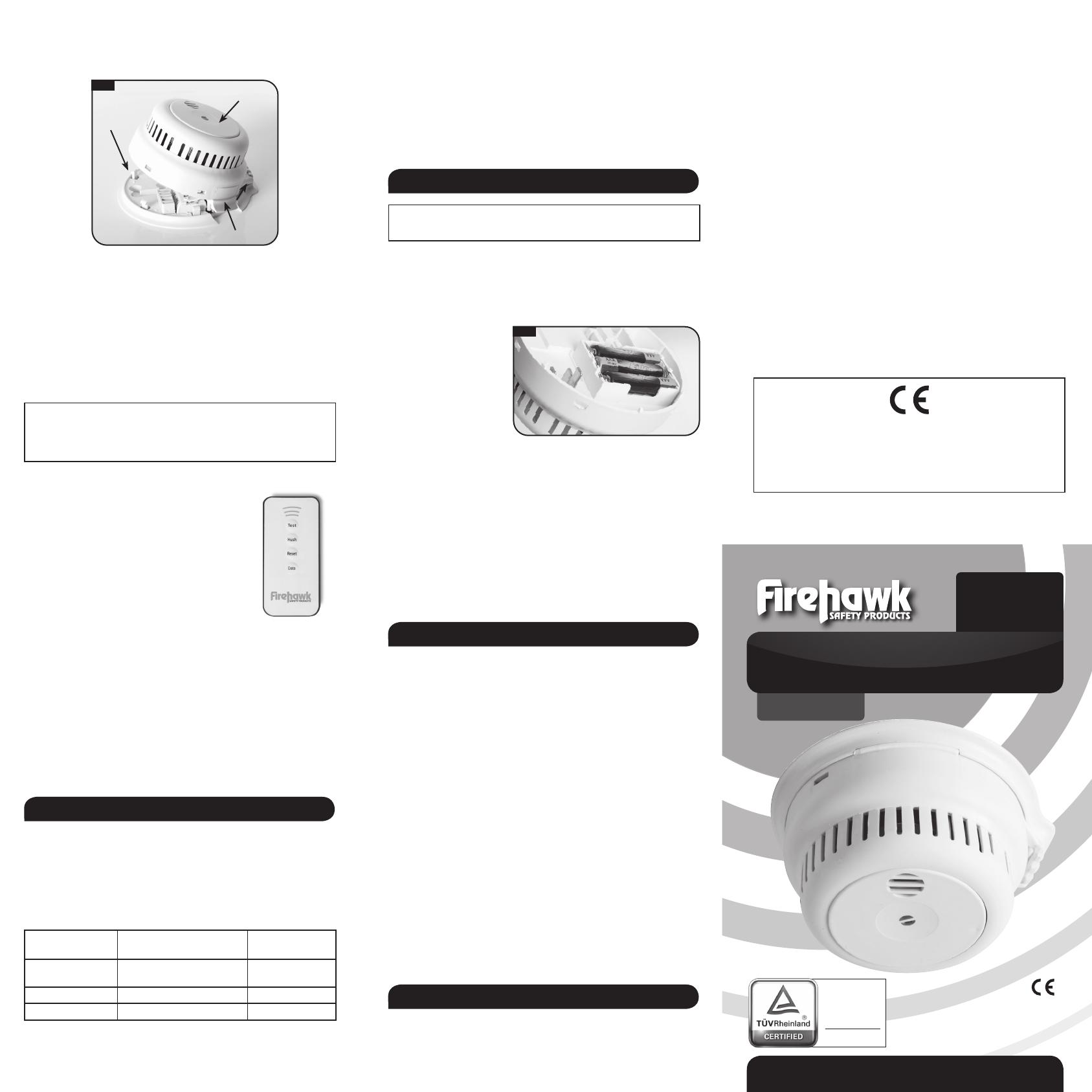
4. Close the alarm making sure the 3 retaining clips are fitting securely. When
removing the alarm from its base-plate, use a small flat bladed screwdriver in
the slots to push away the clips and lever the alarm away.
Fig. 3
Remove this cover when using mini-trunking
Test button
Alarm
retaining
clips (x3)
5. Test the alarm using the large test button (shown above) without mains
power and check it sounds at least 3 times and that the red LED flashes.
6. Turn on the mains power supply. (RB versions only - the alarm may beep once
every minute for around an hour while the battery charge is topped up).
7. Check that the Green LED is on and that the red LED flashes once every
minute.
8. Test the interlink as below to ensure all other alarms in the system sound.
Testing Alarms
Press the test button to test a single alarm and press again after the sounder to
test all interlinked alarms.
IMPORTANT NOTE: Use only the test button to test the alarm
weekly. Do not test the alarm with either a naked flame or
smoke, this will damage and contaminate the alarm causing
nuisance alarms in the future.
Smoke Alarm Remote Control
The remote requires the alarm to be connected to
mains power, it will not work if only powered by batteries.
1. TEST - Pressing the “Test” button on the remote is
the same as pressing the test button on the alarm.
Point the remote at the alarm and press “Test”
to test the alarm. Press again after the alarm has
sounded to test all interlinked alarms. The Test
button can also be used to silence a low battery
warning for approximately 10 hours during which
the red light will flash 3 times every 8 seconds.
2. HUSH - Press and hold the “Hush” button for 2 seconds to silence an alarm
for 10 minutes. If this function is used on an alarm activated by smoke, heat,
or CO it will silence all interconnected alarms. If used on an alarm triggered
by an interlink signal it will only silence others in the system triggered by the
interlink but will not silence the alarm activated by smoke, heat, or CO. The
activated alarm can be identified by its flashing Red LED. Some television and
other universal remote controllers can also be used to silence the alarm, press
and hold any button for 2 seconds.
3. RESET - The “Reset” button will reset the device.
4. DATA - The “Data” button is used with additional equipment to read the
history of alarm activations.
6. USER INFORMATION
Protect your Home Against Fire
Contact your local Fire Brigade for a home safety check, this information is free
and will identify potential fire hazards in and around your home.
Make sure all occupants of the home know what a fire alarm sounds like. Prove
and practise a fire escape plan and arrange a suitable and safe assembly point.
What to Do if the Alarms Sound
Alarms sounds are as follows:
Full alarm indicating Repeating series of 3 beeps every ••• ••• ••• •••
smoke and fire 4 seconds with flashing light
Low Battery Single beep every minute and
3 red flashes every 8 seconds • • • •
Test button jammed One beep every 8 seconds • • • •
Fault Double beep every minute •• •• •• ••
If the full alarm sounds, ensure everyone leaves the building as soon as possible.
• Do not run.
• Do not stop to collect belongings.
FEATURING
Fast-Fix
MANUAL
MAINS POWERED
Smoke Alarms
• If it is safe to do so, close all windows and doors as you escape to prevent
the spread of fire.
• Smoke is the main cause of death from fire. If trapped inside the building,
cover your mouth, conserve breath and crawl to safety.
Do not silence a fire alarm until you know the cause of the alarm and when all
occupants are safely outside the building. The red LED on the test button of
the alarm that has set the system off will be flashing Red once every second.
The lights on the other alarms will be flashing once every minute. The system
can only be silenced from this alarm.
7. CHANGING THE BATTERIES
CAUTION: Danger of explosion if the battery is incorrectly replaced.
Replace only with correct batteries.
The alarm will beep once a minute to indicate the batteries need replacing. If
this happens at night press the test button to silence the warning for 10 hours
and replace the following day. In the event of a low battery warning on the
FHN250RB make sure the green power light is on; if so replace the alarm. If the
green power light is not on, turn the mains power on to the alarm and then
leave the battery to charge. The battery is not replaceable.
To replace the batteries
on the FHN250BB version,
isolate mains power to the
alarm, release the retaining
clips, lower the alarm on its
hinge and refer to Fig. 4.
Changing the 3 AAA batteries (BB versions only)
Remove the alarm from its mounting plate as in section “5 Installation
Procedure” above and replace the 3 AAA batteries taking care to insert the
new ones in the correct orientation. Re-close the alarm taking care to ensure
the alarm is fitted securely to its mounting plate and then test the alarm.
Alarm Maintenance
A regular program of fire alarm maintenance will help to keep your alarm in
good working order.
• Test the alarms weekly making sure that all interconnected alarms in the
system sound within 10 seconds.
• Vacuum the alarms every six months and wipe the external surfaces with a
damp cloth.
8. TROUBLE SHOOTING
Problems are indicated in several ways:
1. The alarm beeps twice every minute indicating a malfunction.
2. The alarm beeps once every minute indicating a low battery. Replace the
battery as above.
3. The alarm beeps once every 8 seconds indicating the test button is
jammed on. Press the test button to reset.
4. The full alarm sounds for no reason. (A repeating series of three beeps with
flashing light). Clean the alarm as above.
5. The alarm does not sound when pressing the test button.
6. The red LED remains steadily on or off. (i.e. does not flash approximately
once every minute, when the unit is not in alarm).
7. The green LED is off. Inspect for obvious damage. Check that the alarm
has been installed in accordance with the instructions, that the alarm is
connected and the supply turned on. In the case of repeated nuisance
alarms, check that it is free from dust, cobwebs and external contamination
from such things as cigarette smoke, drying paint, spray from household
aerosols and steam that may invalidate the warranty. If this does not
correct the problem, do NOT attempt to repair. Other than the replaceable
batteries there are no user serviceable parts. If the alarm is within the
warranty period and terms, indicate the nature of the problem and return
the unit with proof of purchase to the address at the end of this manual.
Units beyond warranty cannot be economically repaired.
9. PRODUCT WARRANTY
Smoke and heat alarms are sensitive life-saving devices. The life of this alarm
can be significantly reduced by adverse environments, incorrect location
and a failure to regularly clean and maintain it according to the instructions.
Incorrect location and a lack of reasonable care may also cause it to
malfunction and will invalidate the warranty.
FireHawk guarantees to you, as a purchaser, that the enclosed fire alarm will
be free from defects in material, workmanship or design under normal use
and service for a period of 6 years for the FHN250BB and 10 years for the
FHN250RB.
This Guarantee is not assignable. Our liability to you, under this guarantee
is limited to repairing or replacing any part which we find to be defective
in material, workmanship or design, free of charge to the customer, upon
sending the alarm with proof of date of purchase, postage paid to FireHawk,
Units 15/17 Manford Industrial Estate, Manor Road, Erith, Kent DA8 2AJ UK.
The terms of this guarantee will not apply in the following circumstances: If
the alarm has been modified, dismantled, contaminated, damaged, neglected
or otherwise abused or altered following the date of purchase, or if it fails to
operate due to incorrect siting, installation, maintenance or inadequate or
over voltage AC electrical power, or damage caused by failure to abide by the
instructions supplied no claim under the guarantee will be entertained. The
liability of FireHawk arising from the sale of this alarm or under the terms of
this guarantee shall not in any case exceed the cost of replacement of the
alarm. In no case, shall FireHawk be liable for consequential loss or damage
resulting from the failure of the alarm or the breach of this or any other
guarantee, express or implied or for damage caused by failure to abide by the
instructions supplied. This guarantee does not affect your statutory rights.
Fireblitz Extinguisher Ltd.
Units 15-17 Manford Industrial Estate, Manor Road. Erith, Kent DA8 2AJ
Telephone: 01322 342238 / Email: Info@fireblitz.co.uk
Fireblitz Extinguisher Ltd
21
1008-CPR-MC 69265792 0001
For Technical Data see product handbook
FRONT
BACK
Fig. 4
Regular Production
Surveillance
Safety
Type Approved
www.tuv.com
ID 1111232979
1008-CPR-MC
69265792 0001


