Page is loading ...
Operating Instructions
<Operations and Settings>
Camera Control Unit
ModelNo.
AK-HCU200P
ModelNo.
AK-HCU200PS
ModelNo.
AK-HCU200E
ModelNo.
AK-HCU200ES
VQT4T42A(E)M1012TY0-FJ
ENGLISH
HowtheOperatingInstructionsareconfigured
<Basics>:
The<Basics>describestheprocedureforconnectionwiththerequiredequipmentandforinstallation.
Beforeinstallingthisunit,besuretotakethetimetoreadthrough<Basics>toensurethattheunitwill
beinstalledcorrectly.
<Operations and Settings> (thismanual):
This<OperationsandSettings>describeshowtooperatetheunitandhowtoestablishitssettings.

2
Contents
Picture monitor (PM) displays 3
Switching the display 3
Transition of displays 3
Description of information displayed 4
Menu operations 9
Displaying and hiding the menus 9
Basic menu operations 9
Setting menu items 11
TOP MENU 11
OPERATION menu 11
MAINTENANCE Menu 21
Web settings 26
Menu operations 26
Description of menus 27
Items when the OPERATION menu is selected 27
Items when the MAINTENANCE menu is selected 31
Table of adjustment setting ranges 35
Connector pin assignment table 38
Index 40
About trademarks and registered trademarks
Microsoft
®
, Windows
®
, Windows
®
7, and Internet Explorer
®
are
registered trademarks or trademarks of Microsoft Corporation in the
United States, Japan, and/or other countries
Intel
®
and Intel
®
Core
TM
are trademarks or registered trademarks of
Intel Corporation and its subsidiaries in the United States and/or other
countries
Adobe
®
and Reader
®
are registered trademarks or trademarks of
Adobe Systems Incorporated in the United States and/or other
countries
SDHC logo is a trademark of SD-3C, LLC
Other company names and product names appearing in this manual
are the registered trademarks or trademarks of their respective
companies
Copyrights
It is prohibited to transfer, copy, disassemble, decompile, and reverse
engineer the software included with the unit, as well as export it in
violation of the export laws
Illustrations and screen images in this manual
Illustrations of the unit and screens may appear different from the
actual unit and screens
The screenshots are used in accordance with the guidelines of
Microsoft Corporation
Abbreviations
The following abbreviations are used in this manual
Microsoft
®
Windows
®
7 Professional SP1 32/64-bit is referred to as
“Windows 7”
Microsoft
®
Windows
®
XP Professional SP3 and
Microsoft
®
Windows
®
XP Home Edition SP3 are referred to as
“Windows XP”
Windows
®
Internet Explorer
®
8 is referred to as “Internet Explorer”
SD memory cards and SDHC memory cards are both referred to as
“memory cards”
They are referred to individually in descriptions in which each of them
is discussed separately
Personal computers are referred to as “computers”
Studio handy camera is referred to as “camera”
Remote operation panel is referred to as “ROP”
Furthermore, the product numbers of equipment are referred to as
follows
Equipment part number Notation in this manual
AK-HC3800G
AK-HC3800
AK-HC3800GS
AK-HRP200G AK-HRP200
AK-HCU200P
AK-HCU200
AK-HCU200PS
AK-HCU200E
AK-HCU200ES

3
Picture monitor (PM) displays
Switching the display
Display the camera statuses, warnings, and other information on the
picture monitor using the operation panel of the ROP
Press the CHARA button of the ROP to display the desired information
The camera statuses, warnings, and other information are cleared when
the CHARA button of the ROP is held down
CHARA button
ROP: AK-HRP200
Transition of displays
When trouble is detected, warning information is automatically displayed on the picture monitor
Even if status information or operation information is already displayed on the picture monitor when trouble is detected, priority is given to the display of
the warning information
The descending sequence of priority for the displays on the picture monitor is as follows: WARNING displays → AUTO displays → STATUS displays →
REMOTE OPERATION menu displays → CCU menu displays → OPERATION displays → no display
When the warning information with the highest priority disappears, the warning information with the next highest priority appears
Sequence of
priority
What is displayed on the
screen
ROP connected
Yes No
Higher
Lower
WARNING displays Warnings are automatically displayed when
trouble is detected
Self-recovery
The warning displays are cleared
Press the CHARA button of the ROP
The display switches to the status screen (IRIS
or status display)
Hold down the CHARA button of the ROP
The warning displays are cleared
Warnings are automatically displayed when
trouble is detected
Self-recovery
The warning displays are cleared
Press the SELECT dial on the unit
When the transition source screen is displayed:
The display switches to the transition source
screen
When the transition source screen is not
displayed:
The warning displays are cleared
AUTO displays Automatically displayed Automatically displayed
STATUS displays Perform display operations using the CHARA
button of the ROP
Press the CHARA button of the ROP
No display → (WARNING) → IRIS → status
displays → Status1 → Status2 → Status3 →
Status4 → Status1
Hold down the CHARA button of the ROP
The status displays end
REMOTE OPERATION menu
displays
When a menu of the CCU
(this unit) is displayed while
the REMOTE OPERATION
menu is displayed, the
REMOTE OPERATION menu
disappears
Display by pressing the CHARA button of the
ROP
Operations using the SELECT dial of the ROP
CCU menu displays
When the REMOTE
OPERATION menu is
displayed while a menu of the
CCU (this unit) is displayed,
the menu of the CCU (this
unit) disappears
Display by pressing the MENU button on the unit
Operations using the SELECT dial on the unit
Display by pressing the MENU button on the unit
Operations using the SELECT dial on the unit
OPERATION displays Automatically displayed Automatically displayed
No display —— ——
4
Description of information displayed
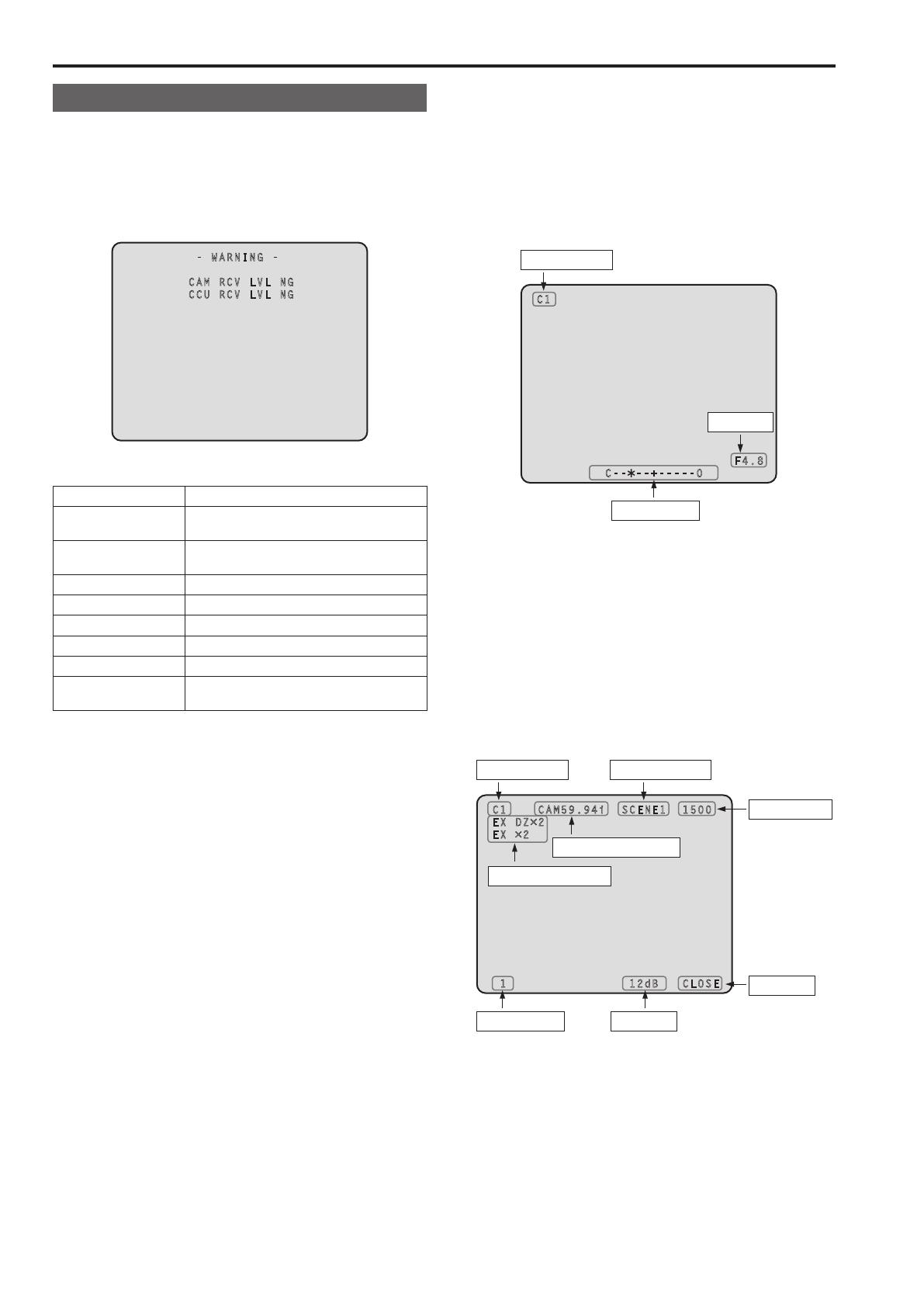
WARNING
The warning information is displayed when trouble is detected in the
unit, camera, or optical fiber multi cable
The warning information items are displayed top aligned
A displayed warning information item is cleared when the status
becomes normal
- WARNING -
CAM RCV LVL NG
CCU RCV LVL NG
Warning information items
Display item Description
CAM RCV LVL NG
The level of the optical signal received by the
camera is low
CCU RCV LVL NG
The level of the optical signal received by the
unit is low
CABLE OPEN The optical fiber multi cable is not connected
CABLE SHORT The optical fiber multi cable is shorted
CAM FAN NG Trouble with the cooling fan of the camera
CCU HIGH TEMP The temperature of the unit is abnormally high
CAM WARM-UP The camera is warming up
ROP SAVING DATA
The data managed by the camera and this unit
is being saved to the memory card in the ROP
To clear the warning information displays, press the button below
ROP (AK-HRP200): CHARA button
IRIS display
When the information is not displayed on the picture monitor, display it
by pressing the CHARA button of the ROP
The camera number is displayed at the top left of the screen, the IRIS
level is displayed at the bottom of the screen, and the IRIS f-value is
displayed at the bottom right of the screen
Set each item to be displayed on the “PM VIEW SETTING” screen that
can be accessed by selecting “MAINTENANCE” on the menu
However, this screen will not appear if the menu’s “IRIS LEVEL” setting
is “OFF”
C1
F4.8
C-- --+-----0
Camera number
IRIS f-value
IRIS level*
*: The IRIS level is displayed based on the IRIS f-value
Status displays
From the IRIS display screen, press the CHARA button of the ROP to
display the statuses
The camera number, scene file number, shutter value, and extender
information are displayed at the top of the screen The ND filter value,
gain value, and IRIS f-value are displayed at the bottom of the screen
Set each item to be displayed on the “PM VIEW SETTING” screen that
can be accessed by selecting “MAINTENANCE” on the menu
However, when the “IRIS LEVEL” setting is “OFF”, the screen will be
displayed first if the CHARA button of the ROP is pressed when the
information is not displayed on the picture monitor
C1 CAM59.94i SCENE1 1500
EX DZ×2
EX ×2
1 12dB CLOSE
Camera number Scene file number
Shutter value
ND filter value Gain value
Extender information
IRIS f-value
Camera format*
*: The camera format value indicates the format of the signal output
from the camera
Picture monitor (PM) displays (Continued)
5
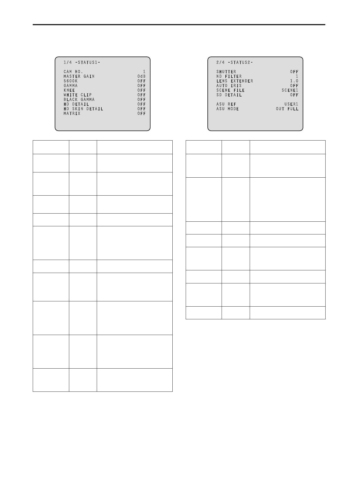
Status displays (page 1 of 4)
From the status display screen, press the CHARA button of the ROP to
display the first page of the status displays
1/4 -STATUS1-
CAM NO. 1
MASTER GAIN 0dB
5600K OFF
GAMMA OFF
KNEE OFF
WHITE CLIP OFF
BLACK GAMMA OFF
HD DETAIL OFF
HD SKIN DETAIL OFF
MATRIX OFF
Item Display
range
Remarks
CAM No 1
│
19
The camera number is displayed here
MASTER GAIN Setting
values on
camera
The master gain value is displayed
here
For the setting values, refer to the
Operating Instructions for the camera
5600K OFF
ON
The status of the 5600K switch is
displayed here
OFF: 3200K, ON: 5600K
GAMMA OFF
ON
The status of the gamma correction is
displayed here
KNEE OFF
ON
The status of the knee function is
displayed here
This function attenuates those parts
that have exceeded the prescribed
level (knee point) of the video signals
to minimize saturation
WHITE CLIP OFF
ON
The status of the white clip function is
displayed here
BLACK GAMMA OFF
ON
The status of the black gamma function
is displayed here
This function changes the
amplification rate of the video signals
in the low-brightness areas
HD DETAIL OFF
ON
The status of the detail function for the
HD signals is displayed here
This function (detail enhancer)
enhances (makes sharper or softer)
the detail image quality of the video
output signals
HD SKIN DETAIL OFF
ON
The status of the skin tone detail
function for the HD signals is displayed
here
This function minimizes or
emphasizes the detail components
applied to the skin tone
MATRIX OFF
ON
The status of the matrix function is
displayed here
This function compensates the
saturation and hue
Status displays (page 2 of 4)
From the status displays (page 1 of 4) screen, press the CHARA button
of the ROP to display the second page
2/4 -STATUS2-
SHUTTER OFF
ND FILTER 1
LENS EXTENDER 1.0
AUTO IRIS OFF
SCENE FILE SCENE1
SD DETAIL OFF
ASU REF USER1
ASU MODE OUT FULL
Item Display
range
Remarks
SHUTTER Setting
values on
camera
The speed of the electronic shutter is
displayed here
For the setting values, refer to the
Operating Instructions for the camera
ND FILTER 1
│
4
The names of the ND filters are
displayed here
The names (each consisting of 4
characters) correspond to filter 1, 2, 3
and 4
Displayed as the filter names are the
names that were set using the unit’s
menu
LENS
EXTENDER
10
20
The magnification of the lens extender
is displayed here
AUTO IRIS OFF
ON
The status of the auto IRIS function is
displayed here
SCENE FILE SCENE1
│
SCENE4
OFF
The selected scene file is displayed
here
SD DETAIL OFF
ON
The status of the detail function for the
SD signals is displayed here
ASU REF USER1
USER2
USER3
FACTORY
The reference file used during auto
setup is displayed here
ASU MODE OUT FULL
OUT EASY
The auto setup mode is displayed here
Picture monitor (PM) displays (Continued)
6
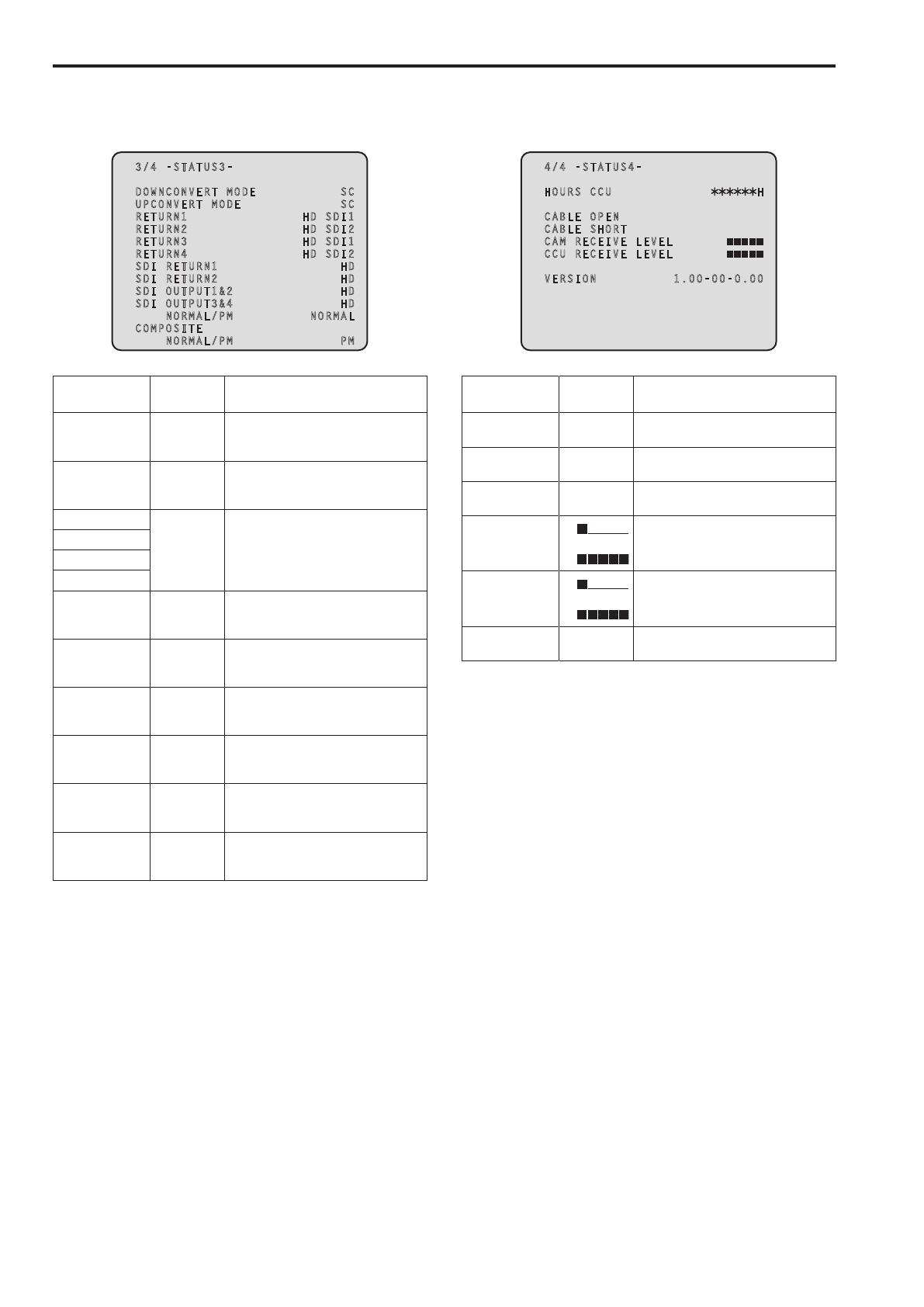
Status displays (page 3 of 4)
From the status displays (page 2 of 4) screen, press the CHARA button
of the ROP to display the third page
3/4 -STATUS3-
DOWNCONVERT MODE SC
UPCONVERT MODE SC
RETURN1 HD SDI1
RETURN2 HD SDI2
RETURN3 HD SDI1
RETURN4 HD SDI2
SDI RETURN1 HD
SDI RETURN2 HD
SDI OUTPUT1&2 HD
SDI OUTPUT3&4 HD
NORMAL/PM NORMAL
COMPOSITE
NORMAL/PM PM
Item Display
range
Remarks
DOWNCONVERT
MODE
SC
SQ
LB
The setting information of the down-
conversion system is displayed here
UPCONVERT
MODE
SC
SQ
LB
The setting information of the
up-conversion system is displayed here
RETURN1 HD SDI1
HD SDI2
SD SDI1
SD SDI2
VBS
The statuses of the input format
allocations for SDI return signals 1 to 4
are displayed here
RETURN2
RETURN3
RETURN4
SDI RETURN1 HD
SD
The format of the return signal to be
input to [HD/SD SDI 1] of the RETURN
IN connectors is displayed here
SDI RETURN2 HD
SD
The format of the return signal to be
input to [HD/SD SDI 2] of the RETURN
IN connectors is displayed here
SDI OUTPUT1&2 HD
SD
The format of the signals to be output
from [1] and [2] of the HD/SD SDI OUT
connectors is displayed here
SDI OUTPUT3&4 HD
SD
The format of the signals to be output
from [3/PM] and [4/PM] of the HD/SD
SDI OUT connectors is displayed here
SDI OUTPUT3&4
NORMAL/PM
NORMAL
PM
The setting information for output from
[3/PM] and [4/PM] of the HD/SD SDI
OUT connectors is displayed here
COMPOSITE
NORMAL/PM
NORMAL
PM
The signal to be output from [OUT/PM]
of the VBS connectors is displayed
here
Status displays (page 4 of 4)
From the status displays (page 3 of 4) screen, press the CHARA button
of the ROP to display the fourth page
4/4 -STATUS4-
HOURS CCU H
CABLE OPEN
CABLE SHORT
CAM RECEIVE LEVEL
CCU RECEIVE LEVEL
VERSION 1.00-00-0.00
Item Display
range
Remarks
HOURS CCU —— The unit’s cumulative operation time is
displayed here
CABLE OPEN —— This item flashes when the optical fiber
multi cable is not connected
CABLE SHORT —— This item flashes when the optical fiber
multi cable is short-circuited
CAM RECEIVE
LEVEL
│
The level of the optical signals received
by the camera is displayed in 5
gradations
CCU RECEIVE
LEVEL
│
The level of the optical signals received
by the unit is displayed in 5 gradations
VERSION —— The unit’s software version is displayed
here
Picture monitor (PM) displays (Continued)
7
Operation displays (manual)
The operation displays appear at the bottom of the screen for 4 seconds
when any of the following operations have been performed with the
operation panel of the ROP
“MASTER GAIN” is changed
“SHUTTER” is changed
“LENS EXT” is changed
“FILTER” is changed
“SCENE FILE” is changed
“REF LOAD” is changed
The display time can be changed from “MAINTENANCE” menu → “PM
OPERATION STATUS” → “STATUS DISP TIME”
FILTER FIL1
Item Display
range
Remarks
MASTER GAIN Setting
values on
camera
The master gain value is displayed
here
(in 3 dB increments)
For the setting values, refer to the
Operating Instructions for the camera
SHUTTER Setting
values on
camera
The speed of the electronic shutter is
displayed here
For the setting values, refer to the
Operating Instructions for the camera
LENS EXT 10
20
The magnification of the lens extender
is displayed here
When the magnification of the
lens extender is set to 2×, “20” is
displayed
Otherwise, “10” is displayed
FILTER 4 characters The name of the ND filter is displayed
here
SCENE FILE SCENE1
│
SCENE4
OFF
This indicates the scene file name
REF LOAD FACTORY
USER1
USER2
USER3
This indicates the reference file that was
loaded using the SCENE command
Operation displays (AUTO)
If the AWB function, ABB function, or AUTO SETUP function has
been activated when a menu is not displayed on the picture monitor,
information on the operation performed appears at the bottom of the
screen
When the AUTO SETUP operations are displayed, they will remain
displayed until the operations are completed
The display is cleared 4 seconds after the operations are completed
If the operations cannot be completed, they will remain displayed until
the NG (error) items of the AUTO function are released
The display time can be changed from “MAINTENANCE” menu → “PM
OPERATION STATUS” → “STATUS DISP TIME”
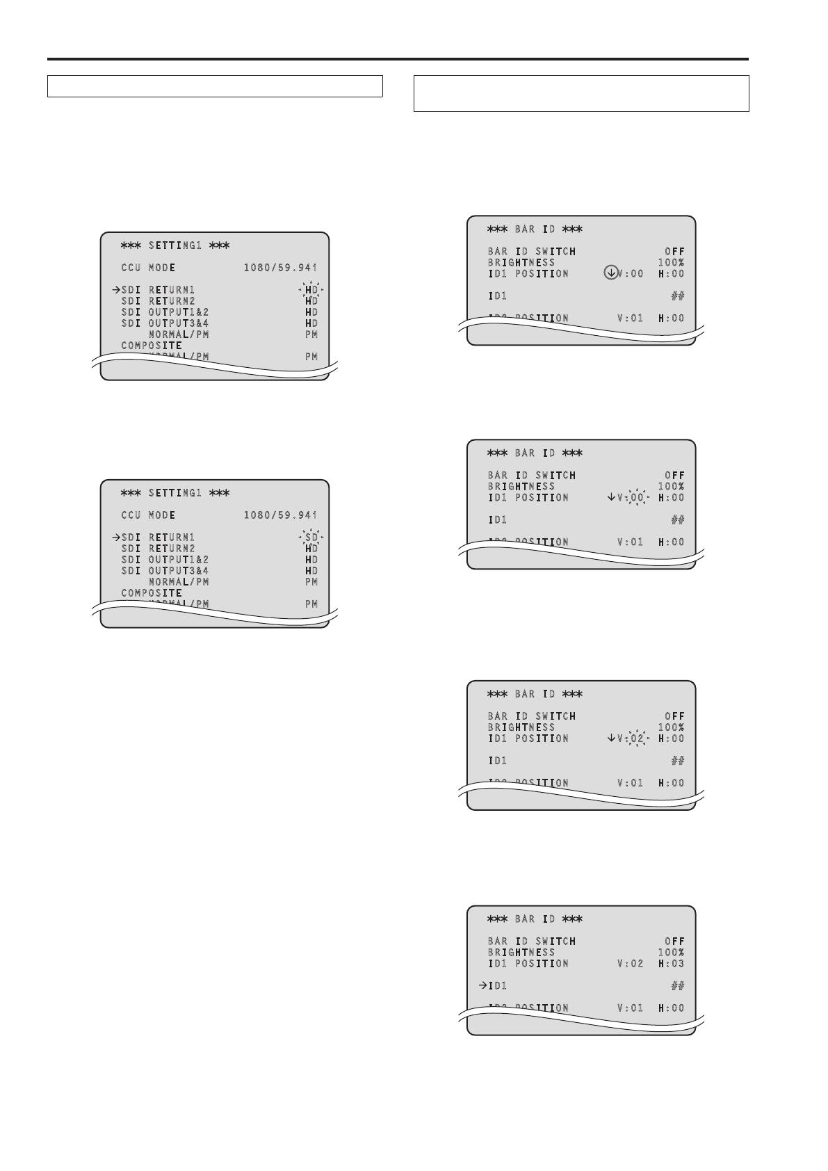
AUTO SETUP: ACTIVE
GAMMA OPERATION
Item
Display description:
Appears on two lines at the bottom of the screen
Top line: status
Bottom line: Detailed information
ABB START ABB: ACTIVE
(None)
AWB START AWB: ACTIVE
(None)
AUTO OK
(Common to
ABB, AWB, and
AUTO SETUP)
ABB: OK AWB: OK AUTO SETUP: OK
(None)
AUTO NG1*
1
(Only for ABB
and AWB)
ABB: NG AWB: NG
Detailed information of the NG (error) message is
displayed here*
1
AUTO SETUP
START*
2
AUTO SETUP: ACTIVE
Detailed information is displayed here*
2
AUTO NG2*
3
(Only for AUTO
SETUP)
AUTO SETUP: NG
Detailed information of the NG (error) message is
displayed here*
3
AUTO BREAK
(Common to
ABB, AWB and
AUTO SETUP)
ABB: BREAK AWB: BREAK AUTO SETUP: BREAK
(None)
AUTO READY
(Only for AUTO
SETUP)
AUTO SETUP: READY
(None)
Picture monitor (PM) displays (Continued)

8
*1: [AUTO NG1 detailed information]
The AUTO NG1 detailed information is displayed flashing on the screen
Rch OUT RANGE
Gch OUT RANGE
Bch OUT RANGE
AWB LOW LIGHT
AWB HIGH LIGHT
*2: [AUTO SETUP operation information]
The AUTO SETUP operation information is displayed on the screen
BSHD OPERATION
FLARE OPERATION
ABB OPERATION
AWB OPERATION
*3: [AUTO NG2 detailed information]
The AUTO NG2 detailed information is displayed flashing on the screen
ABB Gch OUT RANGE
ABB Bch OUT RANGE
ABB Rch OUT RANGE
BSHD Gch OUT RANGE
BSHD Bch OUT RANGE
BSHD Rch OUT RANGE
FLARE Gch OUT RANGE
FLARE Bch OUT RANGE
FLARE Rch OUT RANGE
AWB Gch OUT RANGE
AWB Bch OUT RANGE
AWB Rch OUT RANGE
NOT RUNNING
ILLEGAL MODE(CINEGAMMA)
NOT RUNNING
ILLEGAL MODE(DEXT)
NOT RUNNING
ILLEGAL MODE(SCANREVERSE)
NOT RUNNING
ILLEGAL MODE(BAR)
NOT RUNNING
ILLEGAL MODE(TESTSAW)
Contrast automatic adjustment display
This appears when contrast automatic adjustment (DRS SWITCH) is set
to ON by ROP operation
<DRS ON>
For details on contrast automatic adjustment, refer to the Operating
Instructions for the ROP
Picture monitor (PM) displays (Continued)

9
Menu operations
While viewing the menu screen of the picture monitor, operate the
MENU button and SELECT dial on the front panel
MENU button
SELECT dial
Displaying and hiding the menus
1
Hold down the MENU button
The menu screen appears and the MENU button lights
“TOP MENU” appears first
If the MENU button is held down when the menu is displayed, the
menu closes and the MENU button turns off
Hold down the MENU button Hold down the MENU button
TOP MENU
OPERATION
MAINTENANCE
Basic menu operations
Selecting a menu
1
Press the SELECT dial
Move the cursor to the desired item (OPERATION or
MAINTENANCE) on the “TOP MENU” screen, and then press
the SELECT dial to display the menu screen one level below the
selected item
When the SELECT dial is turned clockwise, the cursor moves
down; conversely, when it is turned counterclockwise, the cursor
moves up
TOP MENU
OPERATION
MAINTENANCE
2
Turn the SELECT dial to move the cursor to the menu
item you want to set, and then press the SELECT dial
OPERATION
SETTING1
SETTING2
HD/SD PHASE
BAR ID
INCOM/MIC
The setting screen one level below the selected menu item appears
SETTING1
CCU MODE 1080/59.94i
SDI RETURN1 HD
SDI RETURN2 HD
SDI OUTPUT1&2 HD
SDI OUTPUT3&4 HD
NORMAL/PM PM
COMPOSITE
NORMAL/PM PM
Moving the cursor to the menu title and then pressing the
SELECT dial redisplays “TOP MENU”
TOP MENU
OPERATION
MAINTENANCE
10
Changing the setting value of a setting item
A number of items and the set values are displayed on the setting
screen at the lowest level
1
Turn the SELECT dial to move the cursor to the menu
item you want to set, and then press the SELECT dial
The setting value of the selected menu item starts flashing and you
can change it
SETTING1
CCU MODE 1080/59.94i
SDI RETURN1 HD
SDI RETURN2 HD
SDI OUTPUT1&2 HD
SDI OUTPUT3&4 HD
NORMAL/PM PM
COMPOSITE
NORMAL/PM PM
2
Turn the SELECT dial to change the value, and then
press the SELECT dial
Turning the SELECT dial changes the setting value and pressing the
SELECT dial confirms the setting value
SETTING1
CCU MODE 1080/59.94i
SDI RETURN1 SD
SDI RETURN2 HD
SDI OUTPUT1&2 HD
SDI OUTPUT3&4 HD
NORMAL/PM PM
COMPOSITE
NORMAL/PM PM
Once the setting value has been confirmed, the flashing stops, and the
cursor can be moved from one menu to another
In some cases, the setting is reflected when the setting value is changed
in the flashing state; in other cases, it is reflected when the SELECT dial
is pressed to confirm the setting value
Menu items with multiple setting items on one line and text
input menu items
1
Turn the SELECT dial to move the cursor to the menu
item you want to set, and then press the SELECT dial
The cursor becomes “” and you can use the SELECT dial to move
the cursor to a setting item in the selected menu item
BAR ID
BAR ID SWITCH OFF
BRIGHTNESS 100%
ID1 POSITION V:00 H:00
ID1 ##
ID2 POSITION V:01 H:00
2
Turn the SELECT dial to move the cursor to the item you
want to set, and then press the SELECT dial
The setting value of the selected item starts flashing and you can
change it
BAR ID
BAR ID SWITCH OFF
BRIGHTNESS 100%
ID1 POSITION V:00 H:00
ID1 ##
ID2 POSITION V:01 H:00
3
Turn the SELECT dial to change the value, and then
press the SELECT dial
Turning the SELECT dial changes the setting value (or characters),
and pressing the SELECT dial confirms the setting value (or
characters)
BAR ID
BAR ID SWITCH OFF
BRIGHTNESS 100%
ID1 POSITION V:02 H:00
ID1 ##
ID2 POSITION V:01 H:00
When the setting value is confirmed and the flashing stops, you can
move the cursor
If you press the SELECT dial while the cursor is on the left of a menu
item, the cursor becomes “” and you can select the menu item
BAR ID
BAR ID SWITCH OFF
BRIGHTNESS 100%
ID1 POSITION V:02 H:03
ID1 ##
ID2 POSITION V:01 H:00
Menu operations (Continued)

11
Setting menu items
TOP MENU
This is the first screen displayed when you hold down the MENU button
Select one of the menus
TOP MENU
OPERATION
MAINTENANCE
OPERATION
Select this to open the OPERATION menu screen
MAINTENANCE
Select this to open the MAINTENANCE menu screen
OPERATION menu
This is the selection screen for the OPERATION menu
Moving the cursor to the “OPERATION” menu title and then pressing the
SELECT dial redisplays “TOP MENU”
OPERATION
SETTING1
SETTING2
HD/SD PHASE
BAR ID
INCOM/MIC
SETTING1
Select this to display the SETTING1 screen
SETTING2
Select this to display the SETTING2 screen
HD/SD PHASE
Select this to display the HD/SD PHASE screen
BAR ID
Select this to display the BAR ID screen
INCOM/MIC
Select this to display the INCOM/MIC screen
SETTING1 Screen
This is the selection screen for the SETTING1 menu
Moving the cursor to the “SETTING1” menu title and then pressing the
SELECT dial redisplays the OPERATION menu one level up
SETTING1
CCU MODE 1080/59.94i
SDI RETURN1 HD
SDI RETURN2 HD
SDI OUTPUT1&2 HD
SDI OUTPUT3&4 HD
NORMAL/PM PM
COMPOSITE
NORMAL/PM PM
indicates the factory default setting
Item
Setting
value
Remarks
CCU MODE
5994 Hz:
1080/5994i
1080/50i
Set the format of the signal to be output
from the unit
50 Hz:
1080/5994i
1080/50i
SDI RETURN1
HD
SD
Set the format of the return signal to be
input to [HD/SD SDI 1] of the RETURN
IN connectors
SDI RETURN2
HD
SD
Set the format of the return signal to be
input to [HD/SD SDI 2] of the RETURN
IN connectors
SDI OUTPUT1&2
HD
SD
Set the format of the signals to be
output from [1] and [2] of the HD/SD
SDI OUT connectors
SDI OUTPUT3&4
HD
SD
Set the format of the signals to be
output from [3/PM] and [4/PM] of the
HD/SD SDI OUT connectors
SDI OUTPUT3&4
NORMAL/PM
NORMAL
PM
Set the signal to be output from [3/PM]
and [4/PM] of the HD/SD SDI OUT
connectors
NORMAL:
Output the main line images
PM:
Output the picture monitor images
COMPOSITE
NORMAL/PM
NORMAL
PM
Set the signal to be output from
[OUT/PM] of the VBS connectors
NORMAL:
Output the main line images
PM:
Output the picture monitor images
When the SDI OUTPUT3&4 NORMAL/PM item and COMPOSITE
NORMAL/PM item are set to “NORMAL”, the menus and statuses will
not be able to be displayed because the picture monitor images will
not be output
When one of items is set to “NORMAL”, the other one is set to “PM”
as both of the items cannot be set to “NORMAL”

12
SETTING2 Screen
This is the selection screen for the SETTING2 menu
Moving the cursor to the “SETTING2” menu title and then pressing the
SELECT dial redisplays the OPERATION menu one level up
SETTING2
FS DELAY NORMAL
HD BAR SELECT ARIB
BAR LPF 7TAP
BAR USER1 75%WHITE
BAR USER2 0%BLACK
SETUP 7.5% OFF
PATHO OFF
indicates the factory default setting
Item
Setting
value
Remarks
FS DELAY
NORMAL
SHORT
Select the delay mode for the HD return
signals
NORMAL:
Matches return signal input that does
not match the sync phase to the
phase of the camera by delaying it by
1 frame
SHORT:
Sets the shortest delay (5 H)
However, if the following conditions
are not met, it is delayed by
1 frame + 5H
HD signal
The SD-HD V item in the HD/SD
PHASE screen is “ADVANCE” or
“0H_SD_DLAY”
When output from this unit is used
as the return signal, the delay is
less than 3H
HD BAR SELECT
FULL
BARS-1
ARIB
BARS-2
BARS-3
BARS-4
BARS-5
BARS-6
Select the color bar signals to be output
from the HD/SD SDI OUT connectors
and VBS connector when “BAR” has
been selected on the operation panel
of the ROP
When they are output in VBS or SD
format, color bars in HD format are
output in the mode specified with
DOWNCONVERT MODE*
FULL:
75 % full field color bar
BARS-1:
Color bar based on the SMPTE
standard
ARIB:
ARIB multi-format color bar
BARS-2:
Color bar based on the EIAJ standard
BARS-3:
Split field color bar
BARS-4:
75 % full field color bar placed in an
area with a 4:3 aspect ratio
(Displayed 40 % gray outside the
area)
BARS-5:
Color bar based on the SMPTE
standard that is placed in an area
with a 4:3 aspect ratio
(Displayed 40 % gray outside the
area)
BARS-6:
Color bar based on the EIAJ standard
that is placed in an area with a 4:3
aspect ratio
(Displayed 40 % gray outside the
area)
Item
Setting
value
Remarks
BAR LPF
OFF
3TAP
5TAP
7TAP
9TAP
Select the filter through which to pass
the color bar signals to be output
from the HD/SD SDI OUT connectors
when BAR has been selected on the
operation panel of the ROP
A higher TAP value will ensure a
smooth rise and fall of the waveforms
and reduce both the overshoot and
undershoot
BAR USER1
75%WHITE
100%WHITE
+I_SIGNAL
–I_SIGNAL
Set user range 1 for when ARIB has
been selected as the HD BAR SELECT
setting
This can be set when “ARIB” is selected
for the HD BAR SELECT item
In the case of another setting, “——”
is displayed and a setting cannot be
selected
BAR USER2
0%BLACK
+Q_SIGNAL
Set user range 2 for when ARIB has
been selected as the HD BAR SELECT
setting
This can be set when “ARIB” is selected
for the HD BAR SELECT item
In the case of another setting, “——”
is displayed and a setting cannot be
selected
SETUP 75%
ON
OFF
Select whether to add the setup 75 %
level to the SD signals to be output from
[OUT/PM] of the VBS connectors
PATHO
ON
OFF
Select ON/OFF for the pathological
signals
*: The DOWNCONVERT MODE setting can be configured by operating
the REMOTE OPERATION menu with the ROP
For details, refer to Operating Instructions <Operations and Settings>
of AK-HRP200
Setting menu items (Continued)
13
HD/SD PHASE Screen
This menu is used for the HD signal and SD signal phase adjustments
Moving the cursor to the “HD/SD PHASE” menu title and then pressing
the SELECT dial redisplays the OPERATION menu one level up
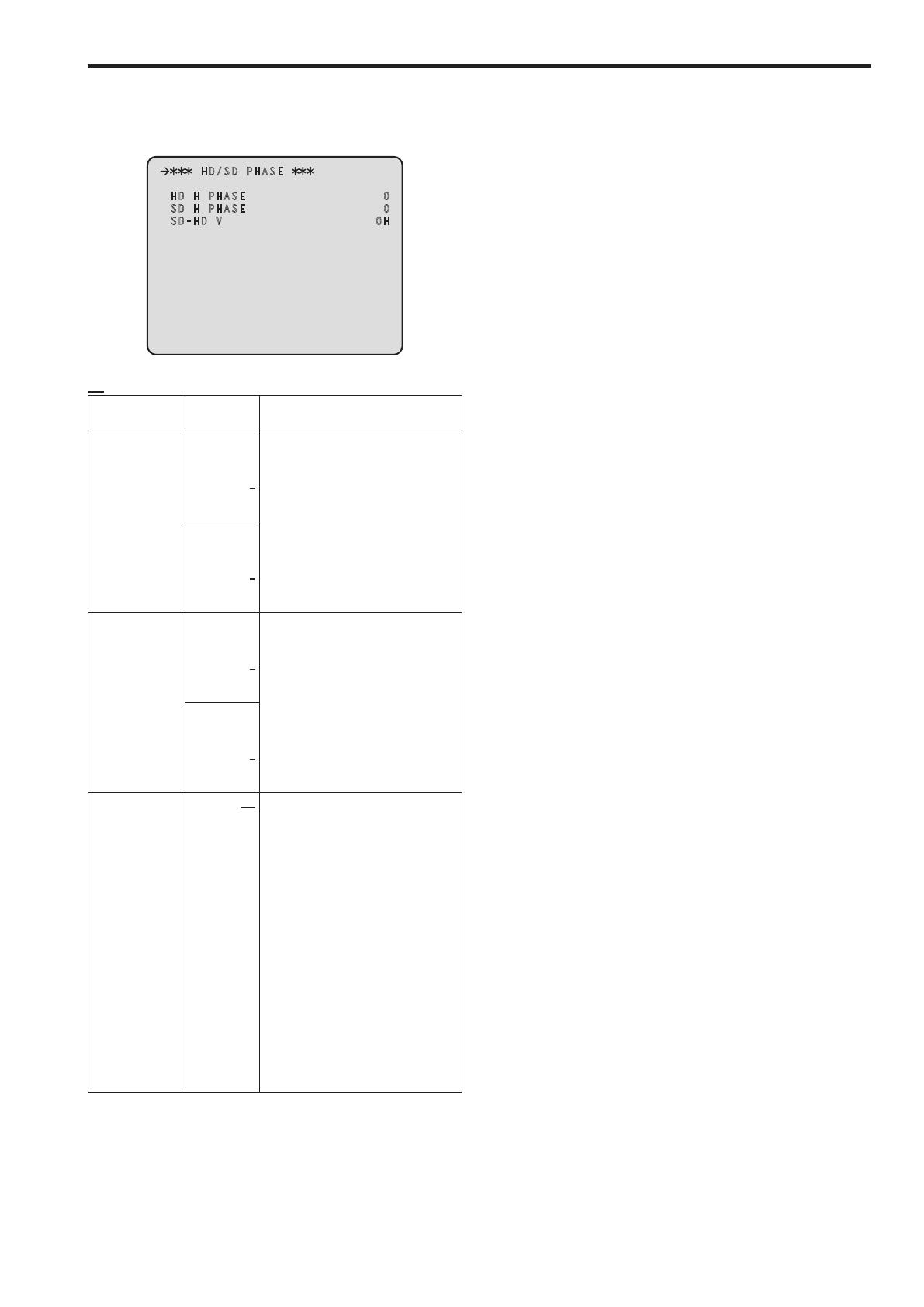
HD/SD PHASE
HD H PHASE 0
SD H PHASE 0
SD-HD V 0H
indicates the factory default setting
Item
Setting
value
Remarks
HD H PHASE
5994 Hz:
–1099
│
0
│
1099
Adjust the horizontal sync phase of
HDTV output in respect to the sync
signals of the system
50 Hz:
–1319
│
0
│
1319
SD H PHASE
5994 Hz:
–857
│
0
│
857
Adjust the horizontal sync phase of
SDTV output in respect to the sync
signals of the system
50 Hz:
–863
│
0
│
863
SD-HD V
0H
ADVANCE
0H
_
SD
_
DLAY
Set the vertical phase of the HDTV
output in relation to the SDTV output
0H:
Sets the vertical phase to the same
phase
ADVANCE:
When the field frequency is 5994 Hz,
the phase advance is 90H
When the field frequency is 50 Hz,
the phase advance is 75H
0H_SD_DLAY:
The SDTV signals are delayed and
set in-phase with the HDTV signals
When the setting of this item is set
to “0H” or “ADVANCE” while the field
frequency is 50 Hz, images in SD
format are delayed by 1 frame + 75
lines only when letterbox is selected
for DOWNCONVERT MODE*
For the relationship with the sync
phase, refer to pages 14 to 19
*: The DOWNCONVERT MODE setting can be configured by operating
the REMOTE OPERATION menu with the ROP
For details, refer to Operating Instructions <Operations and Settings>
of AK-HRP200
Setting menu items (Continued)

14
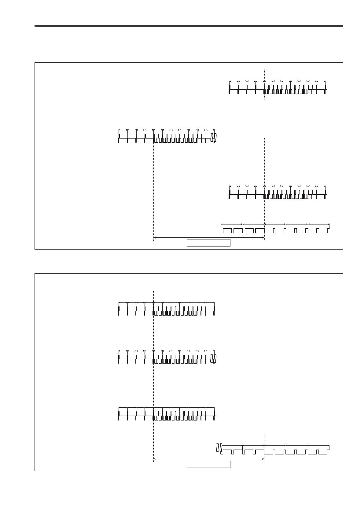
SD signal phase
<1080i/5994 Hz format>
Setting of SD-HD V item: 0H
2 3 4 5 6
1122 1123 1124 1125 1 2 3 4 5 6 7
1122 1123 1124 1125 1 2 3 4 5 6 7
2 3 4 5 6
GEN LOCK Black burst signal
CCU_VBS/SDI (SD)_OUT
CCU_HD_SDI_OUT
90H (HD) LINE
CAM_HD_SDI_OUT
358 BB signal
(525/5994/I)
VBS/SDI (SD) signal
(525/5994/I)
HD_SDI signal
(1125/5994/I)
HD_SDI signal
(1125/5994/I)
Setting of SD-HD V item: ADVANCE (90H)
2 3 4 5 6
1122 1123 1124 1125 1 2 3 4 5 6 7
1122 1123 1124 1125 1 2 3 4 5 6 7
2 3 4 5 6
GEN LOCK Black burst signal
CCU_VBS/SDI (SD)_OUT
90H (HD) LINE
CAM_HD_SDI_OUT
CCU_HD_SDI_OUT
358 BB signal
(525/5994/I)
VBS/SDI (SD) signal
(525/5994/I)
HD_SDI signal
(1125/5994/I)
HD_SDI signal
(1125/5994/I)
Setting menu items (Continued)

15
Setting of SD-HD V item: 0H_SD_DLAY (1FRAM–90H DLY)
2 3 4 5 6
1122 1123 1124 1125 1 2 3 4 5 6 7
1122 1123 1124 1125 1 2 3 4 5 6 7
2 3 4 5 6
GEN LOCK Black burst signal
CCU_VBS/SDI (SD)_OUT
1FRAM–90H (HD) LINE
CAM_HD_SDI_OUT
CCU_HD_SDI_OUT
358 BB signal
(525/5994/I)
VBS/SDI (SD) signal
(525/5994/I)
HD_SDI signal
(1125/5994/I)
HD_SDI signal
(1125/5994/I)
<1080i/50 Hz format>
Setting of SD-HD V item: 0H
624 625 1 2 3 4
1122 1123 1124 1125 1 2 3 4 5 6 7
1122 1123 1124 1125 1 2 3 4 5 6 7
624 625 1 2 3 4
GEN LOCK Black burst signal
CCU_VBS/SDI (SD)_OUT
CCU_HD_SDI_OUT
75H (HD) LINE
CAM_HD_SDI_OUT
443 BB signal
(626/50/I)
VBS/SDI (SD) signal
(626/50/I)
HD_SDI signal
(1125/50/I)
HD_SDI signal
(1125/50/I)
Setting menu items (Continued)

16
Setting of SD-HD V item: ADVANCE (75H)
1122 1123 1124 1125 1 2 3 4 5 6 7
1122 1123 1124 1125 1 2 3 4 5 6 7
624 625 1 2 3 4
624 625 1 2 3 4
GEN LOCK Black burst signal
CCU_VBS/SDI (SD)_OUT
75H (HD) LINE
CAM_HD_SDI_OUT
CCU_HD_SDI_OUT
443 BB signal
(626/50/I)
VBS/SDI (SD) signal
(626/50/I)
HD_SDI signal
(1125/50/I)
HD_SDI signal
(1125/50/I)
Setting of SD-HD V item: 0H_SD_DLAY (1FRAM–75H DLY)
1122 1123 1124 1125 1 2 3 4 5 6 7
1122 1123 1124 1125 1 2 3 4 5 6 7
624 625 1 2 3 4
624 625 1 2 3 4
GEN LOCK Black burst signal
CCU_VBS/SDI (SD)_OUT
1FRAM–75H (HD) LINE
CAM_HD_SDI_OUT
CCU_HD_SDI_OUT
443 BB signal
(626/50/I)
VBS/SDI (SD) signal
(626/50/I)
HD_SDI signal
(1125/50/I)
HD_SDI signal
(1125/50/I)
Setting menu items (Continued)
17
Setting menu items (Continued)
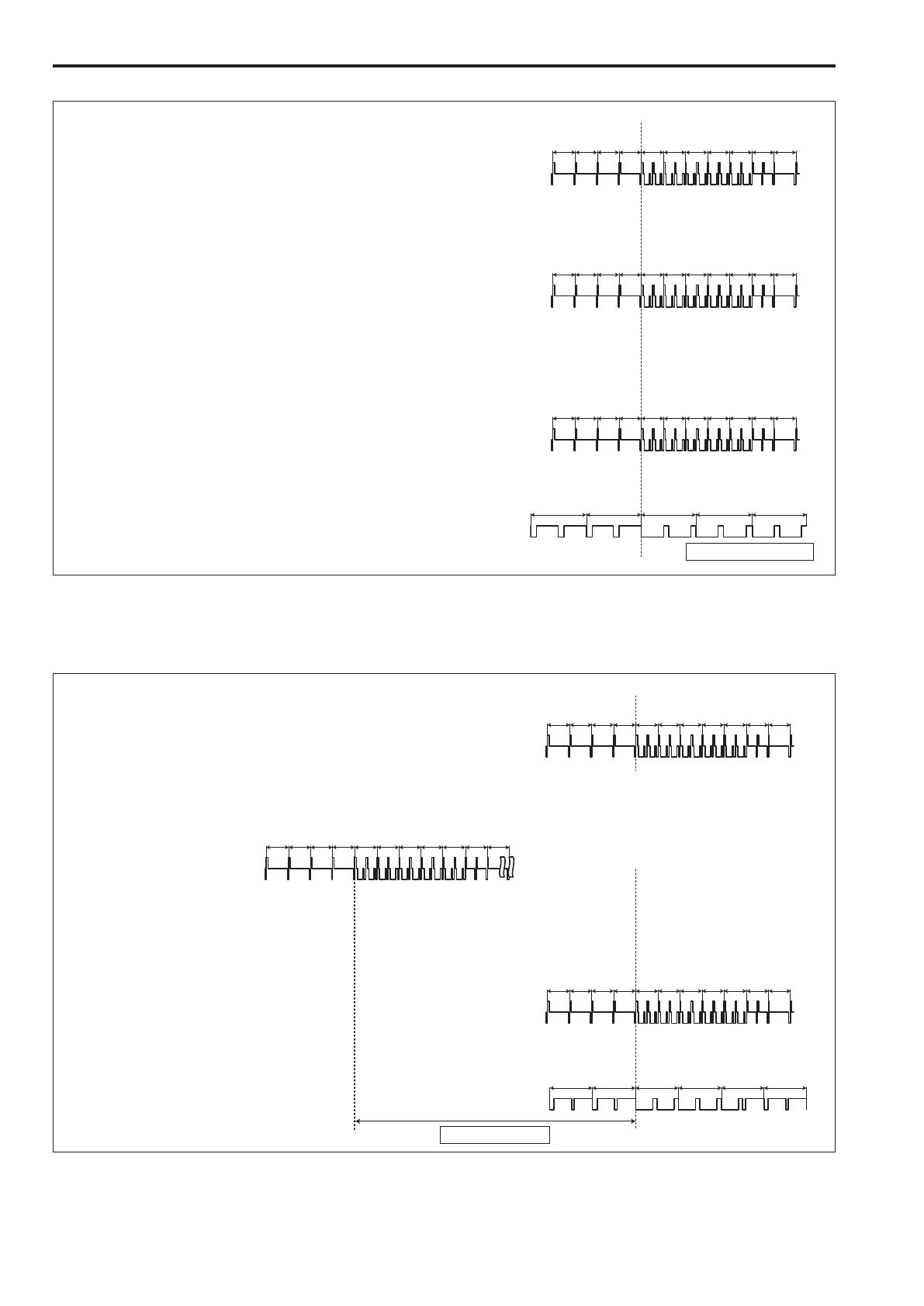
HD signal phase
<1080i/5994 Hz format>
Setting of SD-HD V item: 0H
1122 1123 1124 1125 1 2 3 4 5 6 7
1122 1123 1124 1125 1 2 3 4 5 6 7
1122 1123 1124 1125 1 2 3 4 5 6 7
2 3 4 5 6
GEN LOCK Tri-level sync signal
CCU_VBS/SDI (SD)_OUT
CCU_HD_SDI_OUT
90H (HD) LINE
CAM_HD_SDI_OUT
Tri-level sync signal
(1125/5994/I)
VBS/SDI (SD) signal
(525/5994/I)
HD_SDI signal
(1125/5994/I)
HD_SDI signal
Setting of SD-HD V item: ADVANCE (90H)
1122 1123 1124 1125 1 2 3 4 5 6 7
1122 1123 1124 1125 1 2 3 4 5 6 7
1122 1123 1124 1125 1 2 3 4 5 6 7
2 3 4 5 6
GEN LOCK Tri-level sync signal
CCU_VBS/SDI (SD)_OUT
CAM_HD_SDI_OUT
90H (HD) LINE
CCU_HD_SDI_OUT
VBS/SDI (SD) signal
(525/5994/I)
HD_SDI signal
(1125/5994/I)
HD_SDI signal
Tri-level sync signal
(1125/5994/I)
18
Setting menu items (Continued)
Setting of SD-HD V item: 0H_SD_DLAY (1FRAM–90H DLY)
1122 1123 1124 1125 1 2 3 4 5 6 7
1122 1123 1124 1125 1 2 3 4 5 6 7
1122 1123 1124 1125 1 2 3 4 5 6 7
2 3 4 5 6
GEN LOCK Tri-level sync signal
CCU_VBS/SDI (SD)_OUT
CAM_HD_SDI_OUT
CCU_HD_SDI_OUT
Tri-level sync signal
(1125/5994/I)
VBS/SDI (SD) signal
(525/5994/I)
HD_SDI signal
(1125/5994/I)
HD_SDI signal
1FRAM–90H (HD) LINE
<1080i/50 Hz format>
Setting of SD-HD V item: 0H
1122 1123 1124 1125 1 2 3 4 5 6 7
1122 1123 1124 1125 1 2 3 4 5 6 7
1122 1123 1124 1125 1 2 3 4 5 6 7
624 625 1 2 3 4
GEN LOCK Tri-level sync signal
CCU_VBS/SDI (SD)_OUT
CCU_HD_SDI_OUT
75H (HD) LINE
CAM_HD_SDI_OUT
Tri-level sync signal
(1125/50/I)
VBS/SDI (SD) signal
(626/50/I)
HD_SDI signal
(1125/50/I)
HD_SDI signal
(1125/50/I)

19
Setting menu items (Continued)
Setting of SD-HD V item: ADVANCE (75H)
1122 1123 1124 1125 1 2 3 4 5 6 7
1122 1123 1124 1125 1 2 3 4 5 6 7
1122 1123 1124 1125 1 2 3 4 5 6 7
624 625 1 2 3 4
GEN LOCK Tri-level sync signal
CCU_VBS/SDI (SD)_OUT
CAM_HD_SDI_OUT
75H (HD) LINE
CCU_HD_SDI_OUT
VBS/SDI (SD) signal
(626/50/I)
HD_SDI signal
(1125/50/I)
HD_SDI signal
(1125/50/I)
Tri-level sync signal
(1125/50/I)
Setting of SD-HD V item: 0H_SD_DLAY (1FRAM–75H DLY)
1122 1123 1124 1125 1 2 3 4 5 6 7
1122 1123 1124 1125 1 2 3 4 5 6 7
1122 1123 1124 1125 1 2 3 4 5 6 7
624 625 1 2 3 4
GEN LOCK Tri-level sync signal
CCU_VBS/SDI (SD)_OUT
CAM_HD_SDI_OUT
CCU_HD_SDI_OUT
Tri-level sync signal
(1125/50/I)
VBS/SDI (SD) signal
(626/50/I)
HD_SDI signal
(1125/50/I)
HD_SDI signal
(1125/50/I)
1FRAM–75H (HD) LINE

20
BAR ID Screen
This menu is used to set the BAR IDs displayed on the color bars
Moving the cursor to the “BAR ID” menu title and then pressing the
SELECT dial redisplays the OPERATION menu one level up
BAR ID
BAR ID SWITCH OFF
BRIGHTNESS 100%
ID1 POSITION V:00 H:00
ID1 ##
ID2 POSITION V:01 H:00
ID2 ##
OFFSET V:00 H:00
indicates the factory default setting
Item
Setting
value
Remarks
BAR ID SWITCH
ON
OFF
Set the display of the BAR IDs
displayed on the color bars when the
color bars are displayed to ON or OFF
BRIGHTNESS
0%
│
100%
Set the character color, in units of 10 %,
of the BAR ID displayed on the color
bar when the color bar is displayed
0%: (black), 100%: (white)
ID1 POSITION
V (vertical):
00
│
05
H (horizontal):
00
│
15
Set the display start position of BAR ID1
displayed on the color bars when the
color bars are displayed
Set from which character in the vertical
direction and which character in the
horizontal direction, starting from the top
left of the color bar, to start displaying
the BAR ID using the font size as the
reference
When the coordinates of ID1 and ID2
are the same, bar ID1’s character
string will be placed on top of bar ID2
(BAR ID2 will be below)
When the vertical coordinates are the
same and the horizontal coordinates
differ, the BAR ID with the horizontal
coordinates set later will be placed on
top of the vertical one
ID1
##
□□□□□□□□□□□□□□
Set the character string of BAR ID1
The ID that is set here is displayed on
the color bar
Up to 16 characters can be set
Characters which can be used:
Alphanumeric characters
Spaces
`
! " # % & ' ( )
+ , - / : ; < =
> ? @ [ ] _ ~
When “##” has been input in the
character string, this part is replaced
by the camera number (1 to 19) and
displayed
Item
Setting
value
Remarks
ID2 POSITION
V (vertical):
00
01
│
05
H (horizontal):
00
│
15
Set the display start position of BAR ID2
displayed on the color bars when the
color bars are displayed
Set from which character in the vertical
direction and which character in the
horizontal direction, starting from the top
left of the color bar, to start displaying
the BAR ID using the font size as the
reference
When the coordinates of ID1 and ID2
are the same, bar ID1’s character
string will be placed on top of bar ID2
(BAR ID2 will be below)
When the vertical coordinates are the
same and the horizontal coordinates
differ, the BAR ID with the horizontal
coordinates set later will be placed on
top of the vertical one
ID2
##
□□□□□□□□□□□□□□
Set the character string of BAR ID2
The ID that is set here is displayed on
the color bar
Up to 16 characters can be set
Characters which can be used:
Alphanumeric characters
Spaces
`
! " # % & ' ( )
+ , - / : ; < =
> ? @ [ ] _ ~
When “##” has been input in the
character string, this part is replaced
by the camera number (1 to 19) and
displayed
OFFSET
V (vertical):
00
│
79
H (horizontal):
00
│
89
The display positions of the bar IDs can
be finely adjusted within the font size
range
Using the top left of the font as the
origin point, set the horizontal offset and
vertical offset
Setting menu items (Continued)
/