Page is loading ...

Comtech EF Data is an
AS9100 Rev B / ISO9001:2000 Registered Company
DMD1050
Satellite Modem Board
Installation and Operation Manual
IMPORTANT NOTE: The information contained in this document supersedes all previously published information
regarding this product. Product specifications are subject to change without prior notice.
MN-DMD1050 Revision 9


Comtech EF Data is an
AS9100 Rev B / ISO9001:2000 Registered Company
DMD1050
Satellite Modem Board
Installation and Operation Manual
Part Number MN-DMD1050
Revision 9
Copyright © 2011 Comtech EF Data. All rights reserved. Printed in the USA.
Comtech EF Data, 2114 West 7th Street, Tempe, Arizona 85281 USA, 480.333.2200, FAX: 480.333.2161

This page is intentionally blank.

Table of Contents
CHAPTER 1. INTRODUCTION .................................................................................................. 1–1
1.1 Overview ............................................................................................................................................ 1–1
1.2 DMD1050 Configurations .................................................................................................................... 1–2
1.2.1 Features/Options Installed at Time of Order ........................................................................................... 1–2
1.2.2 Feature Upgrades ..................................................................................................................................... 1–2
1.3 Function Accessibility .......................................................................................................................... 1–2
CHAPTER 2. INSTALLATION.................................................................................................... 2–1
2.1 Installation Requirements ................................................................................................................... 2–1
2.2 Unpacking .......................................................................................................................................... 2–2
2.3 Removal and Assembly ....................................................................................................................... 2–2
2.4 Installation Considerations ................................................................................................................. 2–2
2.5 DMD1050 Initial Configuration Check.................................................................................................. 2–2
2.5.1 Standard DMD1050 Factory Configuration Settings ................................................................................ 2–3
2.6 Modulator Checkout........................................................................................................................... 2–4
2.6.1 Initial Power-Up ....................................................................................................................................... 2–4
2.6.2 M&C Web Browser Setup ........................................................................................................................ 2–4
2.6.3 M&C Terminal Setup ................................................................................................................................ 2–5
2.7 Storage ............................................................................................................................................... 2–6
CHAPTER 3. THEORY OF OPERATION ............................................................................... 3–1
3.1 DMD1050 Hardware ........................................................................................................................... 3–1
3.1.1 DMD1050 L-Band Printed Circuit Card ..................................................................................................... 3–2
3.1.2 DMD1050 Baseband Processing Printed Circuit Card .............................................................................. 3–2
3.2 DMD1050 Functional Block Diagram ................................................................................................... 3–4
3.2.1 Baseband Processing ................................................................................................................................ 3–4
3.2.2 Tx Baseband Processing ........................................................................................................................... 3–4
3.2.3 Rx Baseband Processing ........................................................................................................................... 3–5
3.3 Monitor & Control (M&C) ................................................................................................................... 3–5
3.3.1 Terminal Port/ES-ES Communications (J1) ............................................................................................... 3–6
3.3.2 Terminal Mode Control ............................................................................................................................ 3–6
3.3.3 Modem Terminal Mode Control .............................................................................................................. 3–6
3.3.4 Modem Setup for Terminal Mode ........................................................................................................... 3–7
iii

Table of Contents Revision 9
DMD1050 Satellite Modem Board MN-DMD1050
3.3.5 Connecting the Terminal .......................................................................................................................... 3–7
3.3.6 Terminal Screens ...................................................................................................................................... 3–8
3.4 Modem Remote Communications (RLLP) ............................................................................................. 3–8
3.4.1 RLLP Protocol Structure ........................................................................................................................... 3–8
3.5 Modem Setup for Ethernet M&C (J10) ................................................................................................ 3–8
3.6 M&C Default/Reset Plug Settings (JP5 & JP6) ...................................................................................... 3–9
3.7 Ethernet Data Interface – (J11)............................................................................................................ 3–9
3.8 Internal Clock ................................................................................................................................... 3–13
3.9 Loopback Features (Terrestrial & IF) .................................................................................................. 3–14
3.10 DMD1050 Clocking Options ............................................................................................................... 3–17
3.10.1 TX Clock Options ................................................................................................................................ 3–17
3.10.2 RX Buffer Clock Options ..................................................................................................................... 3–19
3.10.3 RX SAT Clock ...................................................................................................................................... 3–19
3.10.4 SCTE: Serial Clock Transmit External .................................................................................................. 3–19
3.10.5 SCT: Serial Clock Transmit .................................................................................................................. 3–19
3.11 Ethernet Data Interface .................................................................................................................... 3–20
3.12 Reed-Solomon Codec ........................................................................................................................ 3–20
3.12.1 Reed-Solomon Operation in the DMD1050 .......................................................................................3–20
3.12.2 Reed-Solomon Code Rate.................................................................................................................. 3–20
3.12.3 Interleaving ........................................................................................................................................ 3–21
3.13 DMD1050 Automatic Uplink Power Control (AUPC Operation) .......................................................... 3–22
3.13.1 Radyne AUPC ..................................................................................................................................... 3–22
3.13.2 EF AUPC ............................................................................................................................................. 3–23
3.13.3 Near Side AUPC .................................................................................................................................. 3–23
3.14 Asynchronous Overhead Operation (J1) ............................................................................................ 3–25
3.15 Standard IBS ES to ES Mode .............................................................................................................. 3–27
3.16 Enhanced Asynchronous Mode (Radyne Proprietary) ........................................................................ 3–28
3.17 Satellite Control Channel (SCC) - J1.................................................................................................... 3–28
3.17.1 SCC Framing Structure ....................................................................................................................... 3–29
3.17.2 Aggregate Data Rate .......................................................................................................................... 3–30
3.17.3 Overhead Rate Comparison ............................................................................................................... 3–31
3.17.4 Actual Overhead Rate Calculation ..................................................................................................... 3–32
3.17.5 SCC Overhead Channel Setup ............................................................................................................ 3–33
3.18 DMD1050 ID Codes (Feature Upgrades) ............................................................................................ 3–35
3.19 Strap Codes ...................................................................................................................................... 3–35
iv

Table of Contents Revision 9
DMD1050 Satellite Modem Board MN-DMD1050
CHAPTER 4. REAR PANEL INTERFACE ............................................................................. 4–1
4.1 DMD1050 Connections ....................................................................................................................... 4–1
4.2 Compact Flash (J9) .............................................................................................................................. 4–5
4.3 Power Input (J7) ................................................................................................................................. 4–5
4.4 Chassis Connections (Standard) ........................................................................................................... 4–5
4.4.1 EXT REF (J8) .............................................................................................................................................. 4–5
4.4.2 TX L-Band IF (J1) ....................................................................................................................................... 4–5
4.4.3 RX L-Band IF (J2) ....................................................................................................................................... 4–5
4.4.4 ASYNC & Remote Port (J1) - 10 Pin Dual Row Header ............................................................................. 4–6
4.4.5 TERMINAL - Factory use only .................................................................................................................. 4–8
4.4.6 MIL-188-114A (J2) EIA-530 Port RS-422 ................................................................................................... 4–8
4.4.7 ETHERNET M&C (J10) ............................................................................................................................... 4–9
4.5 Ethernet Data Interface (J11) .............................................................................................................. 4–9
4.6 BUC & LNB Power Input (J3)................................................................................................................ 4–9
CHAPTER 5. MAINTENANCE AND TROUBLESHOOTING ........................................... 5–1
5.1 Periodic Maintenance ......................................................................................................................... 5–1
5.2 Troubleshooting ................................................................................................................................. 5–1
5.2.1 Alarm Faults ............................................................................................................................................. 5–2
5.2.2 Alarm Masks............................................................................................................................................. 5–3
CHAPTER 6. TECHNICAL SPECIFICATIONS ..................................................................... 6–1
6.1 Data Rates .......................................................................................................................................... 6–1
6.2 Modulator .......................................................................................................................................... 6–1
6.3 Demodulator ...................................................................................................................................... 6–2
6.4 Plesiochronous Buffer ......................................................................................................................... 6–2
6.5 Monitor and Control ........................................................................................................................... 6–2
6.6 Terrestrial Interfaces ........................................................................................................................... 6–2
6.7 Environmental .................................................................................................................................... 6–2
6.8 Physical .............................................................................................................................................. 6–2
6.9 DMD2050 Data Rate Limits ................................................................................................................. 6–3
6.9.1 Non-DVB ................................................................................................................................................... 6–3
6.9.2 DVB ........................................................................................................................................................... 6–4
v

Table of Contents Revision 9
DMD1050 Satellite Modem Board MN-DMD1050
6.10 DMD1050 BER Specifications .............................................................................................................. 6–6
6.10.1 BER Performance (Viterbi) ................................................................................................................... 6–6
6.10.2 BER Performance (Sequential) ............................................................................................................. 6–7
6.10.3 BER Performance (Viterbi with Reed-Solomon) .................................................................................. 6–8
6.10.4 BER Performance (8PSK Trellis) ........................................................................................................... 6–9
6.10.5 BER Performance (16QAM Viterbi) .................................................................................................... 6–10
6.10.6 BER Performance (16QAM Viterbi with Reed-Solomon) ................................................................... 6–11
6.10.7 BER Performance ((O)QPSK Turbo) .................................................................................................... 6–12
6.10.8 BER Performance (8PSK Turbo) ......................................................................................................... 6–13
6.10.9 BER Performance (16QAM Turbo) ..................................................................................................... 6–14
6.10.11 ACG Output Voltage........................................................................................................................... 6–18
CHAPTER 7. WEB BROWSER.................................................................................................. 7–1
7.1 Web Browser User Interface ............................................................................................................... 7–1
7.2 Configuring Your PC ............................................................................................................................ 7–1
7.2.1 Appearance .............................................................................................................................................. 7–2
7.2.2 Navigation ................................................................................................................................................ 7–2
7.2.3 LED Indicators........................................................................................................................................... 7–3
7.3 GUI Screen Menus .............................................................................................................................. 7–4
7.3.1 Introduction Menu ................................................................................................................................... 7–5
7.3.2 Password Setup ........................................................................................................................................ 7–7
7.3.3 IP and Application Administration ........................................................................................................... 7–9
7.3.4 Monitor and Control Menu .................................................................................................................... 7–14
APPENDIX A. PRODUCT OPTIONS ............................................................................................ A–1
A.1 Hardware Options ............................................................................................................................. A–1
A.2 Internal High-Stability ........................................................................................................................ A–1
A.3 Customized Options ........................................................................................................................... A–1
APPENDIX B. CARRIER CONTROL ...................................................................................... B–1
B.1 States ................................................................................................................................................. B–1
B.2 Carrier Off .......................................................................................................................................... B–1
B.3 Carrier On ........................................................................................................................................... B–1
B.4 Carrier Auto ........................................................................................................................................ B–1
B.5 Carrier VSat ........................................................................................................................................ B–2
B.6 Carrier RTS .......................................................................................................................................... B–2
vi

Table of Contents Revision 9
DMD1050 Satellite Modem Board MN-DMD1050
APPENDIX C. TCP/IP ETHERNET SETUP ........................................................................... C–1
C.1 Introduction ....................................................................................................................................... C–1
C.2 TCP/IP Network Configuration ............................................................................................................ C–1
C.3 Network Configuration Summary ........................................................................................................ C–3
C.4 Ethernet Test...................................................................................................................................... C–3
C.5 Testing the Ethernet Connection using the Ping Program (Optional) .................................................... C–6
APPENDIX D. WEB BROWSER SETUP GUIDE ............................................................... D–1
D.1 Introduction ...................................................................................................................................... D–1
D.2 Required Items .................................................................................................................................. D–1
D.3 Web Interface Setup Guidelines ......................................................................................................... D–1
D.3.1 Preparing the DMD1050 for Web Setup ................................................................................................. D–1
D.4 IP Network Change from the Initial Web Setup .................................................................................. D–4
D.4.1 Configuring the modem .......................................................................................................................... D–4
D.4.2 Configuring the Computer ...................................................................................................................... D–5
D.5 WEB Users Setup and Configurations Controls Options ....................................................................... D–6
D.5.1 Change Authentication Password ........................................................................................................... D–7
D.5.2 Boot Mode Options (Reference only) ..................................................................................................... D–8
APPENDIX E. USER INTERFACE CONNECTIONS .......................................................... E–1
E.1 User Interface Connections ................................................................................................................. E–1
APPENDIX F. ETHERNET DATA INTERFACE ................................................................... F–1
F.1 Introduction ....................................................................................................................................... F–1
F.2 Point-to-Point Applications ................................................................................................................. F–2
F.3 The Importance of Transparent Operation .......................................................................................... F–3
F.4 Point-to-Multipoint Applications ......................................................................................................... F–4
F.5 High Speed Mesh Applications ............................................................................................................ F–5
F.6 Low Speed Mesh Applications............................................................................................................. F–6
F.7 Remote Monitor and Control via SNMP .............................................................................................. F–7
F.8 Enhanced Quality of Service (QOS)...................................................................................................... F–8
vii

Table of Contents Revision 9
DMD1050 Satellite Modem Board MN-DMD1050
F.8.1 Normal QOS ............................................................................................................................................. F–9
F.8.2 Port Based QOS ........................................................................................................................................ F–9
F.8.3 Fair Weighted Queuing ............................................................................................................................ F–9
F.8.4 Strict Priority Queuing .............................................................................................................................. F–9
F.8.5 Satellite Packet Error Checking .............................................................................................................. F–10
F.8.6 Automatic Learning and Aging ............................................................................................................... F–10
F.8.7 Internal Buffer and Throttle ................................................................................................................... F–10
F.8.8 Adding Acceleration, Compression, Network Security, and Traffic Shaping .......................................... F–11
F.8.9 Any Data Rate, Any Modulation Type, Any FEC, Any Application .......................................................... F–11
APPENDIX G. DMD1050 STRAP CODES .................................................................................. G–1
G.1 Introduction ...................................................................................................................................... G–1
APPENDIX H. SOFTWARE UPGRADE PROCEDURE .................................................... H–1
H.1 Software Upgrade Procedure ............................................................................................................. H–1
H.2 Terminal Software Upgrade ............................................................................................................... H–1
H.3 Required Equipment .......................................................................................................................... H–1
H.4 Upgrade Procedure............................................................................................................................ H–1
H.5 Demonstration Procedure.................................................................................................................. H–2
H.6 Canceling Demonstration Mode ......................................................................................................... H–3
H.7 Web Browser Software Upgrade ........................................................................................................ H–4
H.8 Monitor and Control .......................................................................................................................... H–4
viii

PREFACE
About this Manual
This manual describes the installation and operation of the DMD1050.
Conventions and References
Trademarks
Product names mentioned in this manual may be trademarks or registered trademarks of their
respective companies and are hereby acknowledged.
Related Documents
• Department of Defense (DOD) MIL-STD-188-165A, Interoperability and Performance
Standards for SHF Satellite Communications PSK Modems (FDMA Operation) (dated
November 2005)
• Department of Defense (DOD) MIL-STD-188-114A, Electrical Characteristics of Digital
Interface Circuits
• EN300-421 and EN301-210 ETSI
• INTELSAT Earth Station Standards IESS-308, -309, -310, and -315
Cautions and Warnings
IMPORTANT or NOTE indicates a statement associated with the task
being performed or information critical for proper equipment function.
IMPORTANT
CAUTION indicates a hazardous situation that, if not avoided, may result in
minor or moderate injury. CAUTION may also be used to indicate other
unsafe practices or risks of property damage.
CAUTION
WARNING indicates a potentially hazardous situation that, if not avoided,
could result in death or serious injury.
i

DMD1050 Revision 9
Preface MN-DMD1050
Warranty Policy
Comtech EF Data products are warranted against defects in material and workmanship
for a period of two years from the date of shipment. During the warranty period, Comtech
EF Data will, at its option, repair or replace products that prove to be defective. Repairs
are warranted for the remainder of the original two year warranty, or a 90 day extended
warranty, whichever is longer.
For equipment under warranty, the owner is responsible for freight to Comtech EF Data
and all related customs, taxes, tariffs, insurance, etc. Comtech EF Data is responsible for
the freight charges only for return of the equipment from the factory to the owner.
Comtech EF Data will return the equipment by the same method (i.e., Air, Express,
Surface) as the equipment was sent to Comtech EF Data.
All equipment returned for warranty repair must have a valid RMA number issued prior to
return and be marked clearly on the return packaging. Comtech EF Data strongly
recommends all equipment be returned in its original packaging.
Comtech EF Data Corporation’s obligations under this warranty are limited to repair or
replacement of failed parts, and the return shipment to the buyer of the repaired or
replaced parts.
Limitations of Warranty
The warranty does not apply to any part of a product that has been installed, altered,
repaired, or misused in any way that, in the opinion of Comtech EF Data Corporation,
would affect the reliability or detracts from the performance of any part of the product, or
is damaged as the result of use in a way or with equipment that had not been previously
approved by Comtech EF Data Corporation.
The warranty does not apply to any product or parts thereof where the serial number or the
serial number of any of its parts has been altered, defaced, or removed.
The warranty does not cover damage or loss incurred in transportation of the product.
The warranty does not cover replacement or repair necessitated by loss or damage from
any cause beyond the control of Comtech EF Data Corporation, such as lightning or
other natural and weather related events or wartime environments.
The warranty does not cover any labor involved in the removal and or reinstallation of
warranted equipment or parts on site, or any labor required to diagnose the necessity for
repair or replacement.
The warranty excludes any responsibility by Comtech EF Data Corporation for incidental or
consequential damages arising from the use of the equipment or
products, or for any inability to
use them either separate from or in combination with any other equipment or products.
A fixed charge established for each product will be imposed for all equipment returned
for warranty repair where Comtech EF Data Corporation cannot identify the cause of the
reported failure.
ii

DMD1050 Revision 9
Preface MN-DMD1050
Exclusive Remedies
Comtech EF Data Corporation’s warranty, as stated is in lieu of all other warranties,
expressed, implied, or statutory, including those of merchantability and fitness for a
particular purpose. The buyer shall pass on to any purchaser, lessee, or other user of
Comtech EF Data Corporation’s products, the aforementioned warranty, and shall
indemnify and hold harmless Comtech EF Data Corporation from any claims or liability
of such purchaser, lessee, or user based upon allegations that the buyer, its agents, or
employees have made additional warranties or representations as to product preference
or use.
The remedies provided herein are the buyer’s sole and exclusive remedies. Comtech
EF Data shall not be liable for any direct, indirect, special, incidental, or consequential
damages, whether based on contract, tort, or any other legal theory.
iii

DMD1050 Revision 9
Preface MN-DMD1050
Customer Support
Support Business Hours - Monday through Friday - 8:00 a.m. to 5:00 p.m. (MST)
Comtech EF Data & Radyne
• Satellite Modems
• Modem Accessories
• Amplifiers
• Converters
• Transceivers
• Terminals
• IP-Enabled Satellite Modems
• IP-Based Modem Accessories
• Encapsulators, Receivers, Filtering &
Encryption
• turboIP® Performance Enhancement
Proxies (PEP)
• SkyWire™ MDX420 Satellite Network
Gateway
• Vipersat Network Products
• IP-Enabled Satellite Modems used in
conjunction with VMS
After Hours and Weekends:
Comtech
Tel: +1.480.333.4357
Memotec Products
• CX-U: RAN Optimization
• NetPerformer: Satellite Routers
Stampede Technologies
• FX Series Application Delivery Controllers
• FX Series WAN Optimization Controllers
Tel: +1.480.333.4357
Fax: +1.480.333.2500
Email: [email protected]
Tel: +1.480.333.2433
Fax: +1.480.333.2161
Email: cdmipsupport@comtechefdata.com
Tel: +1.510.252.1462 - select option #2
Fax: +1.510.252.1695
Email: [email protected]
Radyne
Tel: +1.602.980.5220
Tel: +1.514.738.4781
Fax: +1.514.738.4436
Email: [email protected]
Business Hours - Monday Through Friday
8:00 a.m. to 5:00 p.m. (EST)
Tel: +1.937.291.5035
Fax: +1.937.291.5040
Email: stampedesupport@comtechefdata.com
Business Hours - Monday Through Friday
8:30 a.m. to 5:30 p.m. (EST)
After Hours and Weekends: +1.937.291.5035
iv

Chapter 1. Introduction
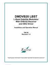
This chapter provides an overview of the DMD1050 Satellite Board Modem, which is designed
for satellite IP, telecom, video and internet applications.
1.1 Overview
• Duplex L-Band modem
• MIL-STD-188-165A standards
• IDR, IBS and DVB
• Data rates up to 20 Mbps
Figure 1-1. DMD1050 Satellite Board Modem (Top View)
MN-DMD1050 1–1
Revision 9

DMD1050 Satellite Modem Board Introduction
The DMD1050's impressive remote accessibility rivals all others in the field. Remote control via
RLLP (Radyne Link Level Protocol), Ethernet 10 Base-T SNMP and Web Browser includes
control of all the modem's features plus software maintenance. The unit presents monitor and
control functions on the screen.
Additional options and configuration (such as Monitor and Control (M&C) Functions) can be
activated in seconds via the Web Browser.
Compatibility with current modems, such as the DMD2050, DMD50, DMD20 and the DISA
certified MIL-188-165 compliant DMD15L are maintained for seamless substitution and addition
to existing systems.
This unit offers built in Standard Interfaces that are selectable from MIL-188-114A and a Dual
Port Ethernet Bridge.
1.2 DMD1050 Configurations
The DMD1050 can be configured in the following different ways:
• Features and options that are installed when the unit is ordered
• Feature upgrades
• Hardware options that the user can install at their own location
• Options that are installed to a unit that is sent to a comtech service center
1.2.1 Features/Options Installed at Time of Order
Features installed at the time of ordering are the options pre-installed/initialized in the factory
prior to shipment. These can be reviewed from the web browser. Refer to Section 4, User
Interfaces for information on how to view these features.
Factory installed options are chassis and board configurations that are introduced during
manufacture.
1.2.2 Feature Upgrades
Feature Upgrades are a simple and quick way of changing the feature set of an installed modem.
Feature upgrades are how most DMD1050 options are implemented. Features may be purchased
at any time by contacting a salesperson. Refer to Section 3 and Appendix D, for information on
how upgrade features.
1.3 Function Accessibility
All functions can be accessed with a terminal or personal computer via a serial link for complete
remote monitoring and control capability.
MN-DMD1050 1–2
Revision 9

Chapter 2. Installation
This section provides instructions on unpacking and installation, as well as storage of the unit.
2.1 Installation Requirements
Installation of the DMD1050 Modem Board requires adequate planning by the user to ensure no
damage will occur to the unit. Package design considerations for the modem board include
mounting, temperature limits, adequate ventilation, limited vibration, no exposure to
condensation/ moisture and a stable power source.
Mating connectors are supplied with each unit. A full description of the modems pin outs can be
found in Section 4. Appendix E gives details of the various connectors and mating connectors
supplied.
WARNINGS
1. The DMD1050 contains a Lithium Battery
DANGER OF .
EXPLOSION exists if the battery is incorrectly replaced. Replace only
with the same or equivalent type recommended by the manufacturer.
Dispose of used batteries in accordance with local and national
regulations
2. Make sure to eliminate the potential for Static Discharge that can
damage the Modem Board.
3. There are no user-serviceable parts or configuration settings located
inside the DMD105.
CAUTION
Before connecting power to the unit, disconnect the transmit output from the
operating ground station equipment. Communication traffic can be disrupted
by connecting power to a unit when the configuration settings are not known
and may be incorrect.
Make sure to obey proper ESD practices to avoid damaging the unit.
MN-DMD1050 2–1
Revision 9

DMD1050 Satellite Modem Board Installation
2.2 Unpacking
The DMD1050 Universal Satellite Modem was carefully packaged to avoid damage and should
arrive complete with the following items for proper installation:
• DMD1050 Modem Board
• Installation and Operation Manual
2.3 Removal and Assembly
The DMD1050 Modem Unit is shipped fully assembled.
CAUTION
Make sure to obey proper ESD practices to avoid damaging the unit.
Carefully unpack the unit and ensure that all of the above items are in the carton. If the available
Power cable and Data cables can be supplied.
2.4 Installation Considerations
User must consider adequate ventilation when installing the DMD1050 into the final package.
The recommended ambient temperature for the modem board should be between 10° and 35°C,
and held constant for best equipment operation. Ventilated air should be clean and relatively dry.
Modem board must have adequate spacing between other products to avoid cross talk or electrical
shorts. Modems should not be placed immediately above a high-heat or EMF Generator to ensure
the output signal integrity and proper receive operation.
Do not install the DMD1050 in an unprotected outdoor location where there is direct contact with
rain, snow, wind or sun. The only tools required for installing the DMD1050 are five (5)
mounting holes. Caution should be exercised when installing the modem board to ensure the
modem board is not bent, warped or compressed to ensure the unit does not get damaged.
2.5 DMD1050 Initial Configuration Check
The DMD1050 is shipped from the factory with preset factory defaults. Upon initial power-up, a
user check should be performed to verify the shipped modem configuration. Refer to Section 4;
User Interfaces, to locate and verify that the following configuration settings are correct:
First, make sure to select the DMD1050 Interface Type (MIL-188-114A or
Ethernet Data Interface) BEFORE you install the mating connectors. Failure
to do this can damage the Data Interface.
MN-DMD1050 2–2
Revision 9

DMD1050 Satellite Modem Board Installation
2.5.1 Standard DMD1050 Factory Configuration Settings
Implementing Strap Code 26 can set the following modem configuration.
Refer to Table 4-4 for an explanation and tabular listing of available Strap
Codes. The Frequency and Modulator Output Power are set independently of
IMPORTANT
the strap code.
Modulator:
Data Rate: 2.048 Mbps
Mode: Closed Network
Satellite Framing: None
Scrambler: V.35 (IESS)
Inner FEC: 1/2 Rate Viterbi
Outer FEC: Disabled
Modulation: QPSK
Frequency: 950 MHz
Modulator Output Power: -20 dBm
Demodulator:
Data Rate: 2.048 Mbps
Mode: Closed Network
Satellite Framing: None
Scrambler: V.35 (IESS)
Inner FEC: 1/2 Rate Viterbi
Outer FEC: Disabled
Modulation: QPSK
Frequency: 950 MHz
To lock up the modem, enter ‘IF Loopback Enable’ under the Test Menu, or connect a Loopback
Cable from TX port to RX port.
Using the modem’s loopback capabilities with the Ethernet data interface can cause
undesirable network loops. Before you do any data test with an Ethernet interface,
make sure to use two modems connected back-to-back. If you use one modem and a
IMPORTANT
loopback, the results will not be as desired.
MN-DMD1050 2–3
Revision 9

DMD1050 Satellite Modem Board Installation
IMPORTANT
2.6 Modulator Checkout
The following descriptions assume that the DMD1050 is installed in a suitable location with
clean, stable DC power. Make sure that DC spikes are not present during initial power up.
2.6.1 Initial Power-Up
Make sure that the modem’s input DC power is clean, stable and free of spikes.
If the input DC power is of poor quality, it will damage the unit .
Before connecting power to the unit, disconnect the transmit output from the
operating ground station equipment. Communication traffic can be disrupted
by connecting power to a unit when the configuration settings are not known
and may be incorrect.
New units are shipped with the transmit carrier set to OFF.
The initial field checkout of the modem can be accomplished from the Web Browser or Terminal
Mode. The Web Browser and Terminal Mode has the advantage of providing full screen access
to all of the modem’s parameters, but requires a separate terminal or computer running a
Terminal Program. The modem is configured with the Web Browser enabled.
2.6.2 M&C Web Browser Setup
The Ethernet M&C Interface requires a standard RJ45 Male connector. The Ethernet Interface is
shipped from the factory in an addressable defaulted condition that allows the user to access the
unit. This condition is identified as IP TEST MODE. .
Boot Modes: IPTEST
IP Address Mask: 255.255.255.000
Modem IP Address: 192.168.0.238
Server IP Address: 192.168.000.101
Router IP Address: 192.168.000.102
Refer to section C & D for proper setup of the Ethernet M&C Interface.
Connect an Ethernet cable between the unit and a computer that has web browser capability.
Access the browser and enter the default web address for the unit.
Refer to Section 4
for a complete description of the GUI Interface operation and parameters.
Refer to Appendix C and Appendix D for proper setup of the TCP-IP interface and Web Browser
Setup.
MN-DMD1050 2–4
Revision 9
/