Page is loading ...

1
PNEG-339
1100 SERIES SINGLE FAN
PORTABLE DRYER
MODELS
A
I R S T R E A M
G
R A I N
C
O N D I T I O N I N G
S
Y S T E M S
DRYER OPERATION
A N D S E R V I C E M A N U A L
1 9 9 7

2

3
Warranty.......................................................................................................................4
Safety First...................................................................................................................5
Safety Alert Decals.......................................................................................................6
Safety Precautions.......................................................................................................7
Dryer Control Panel Featuring The Electronic Monitoring Control System.......................8
Safety Circuit Shutdown Messages......................................................................13
Dryer Pre Start Checks...............................................................................................14
Pre Season Inspection..........................................................................................14
Dryer Start Up...................................................................................................................18
Continuous Flow And Continuous Batch Start Up Procedure..............................18
Continuous Flow Metering Roll Settings...............................................................19
Continuous Batch Metering Roll And Timer Settings................................................22
1100 Series Dryer Service Guide.....................................................................................23
Seasonal Inspection And Service.........................................................................24
Suggested Lubricants..........................................................................................25
Fan Propellor Removal And Installation...............................................................26
Fan Motor Removal And Installation....................................................................27
Heater Parts Removal And Installation................................................................28
Metering Roll Servicing........................................................................................29
How To Determine A Metering Roll Problem........................................................30
Wiring Diagrams...................................................................................................31
Trouble Analysis Procedure...................................................................................41
Quick Reference Guide........................................................................................46
Notes...................................................................................................................47
1100 SERIES DRYER OPERATION AND SERVICE
TABLE OF CONTENTS

4
WARRANTY
EXCEPT FOR THE ABOVE STATED EXPRESS LIMITED WARRANTIES, GSI MAKES NO WARRANTY OF
ANY KIND, EXPRESSED OR IMPLIED, INCLUDING, WITHOUT LIMITATION, WARRANTIES OF MER-
CHANTABILITY OR FITNESS FOR A PARTICULAR PURPOSE OR USE IN CONNECTION WITH (i) PROD-
UCT MANUFACTURED OR SOLD BY GSI OR (ii) ANY ADVICE, INSTRUCTION, RECOMMENDATION OR
SUGGESTION PROVIDED BY AN AGENT, REPRESENTATIVE OR EMPLOYEE OF GSI REGARDING OR
RELATED TO THE CONFIGURATION, INSTALLATION, LAYOUT, SUITABILITY FOR A PARTICULAR PUR-
POSE, OR DESIGN OF SUCH PRODUCT OR PRODUCTS.
IN NO EVENT SHALL GSI BE LIABLE FOR ANY DIRECT, INDIRECT, INCIDENTAL OR CONSEQUEN-
TIAL DAMAGES, INCLUDING, WITHOUT LIMITATION, LOSS OF ANTICIPATED PROFITS OR BENEFITS.
PURCHASER'S SOLE AND EXCLUSIVE REMEDY SHALL BE LIMITED TO THAT STATED ABOVE, WHICH
SHALL NOT EXCEED THE AMOUNT PAID FOR THE PRODUCT PURCHASED. THIS WARRANTY IS NOT
TRANSFERABLE AND APPLIES ONLY TO THE ORIGINAL PURCHASER. GSI SHALL HAVE NO OBLIGA-
TION OR RESPONSIBILITY FOR ANY REPRESENTATIVE OR WARRANTIES MADE BY OR ON BEHALF
OF ANY DEALER, AGENT OR DISTRIBUTOR OF GSI.
GSI ASSUMES NO RESPONSIBILITY FOR FIELD MODIFICATIONS OR ERECTION DEFECTS WHICH
CREATE STRUCTURAL OR STORAGE QUALITY PROBLEMS. MODIFICATIONS TO THE PRODUCT NOT
SPECIFICALLY COVERED BY THE CONTENTS OF THIS MANUAL WILL NULLIFY ANY PRODUCT WAR-
RANTY THAT MIGHT HAVE BEEN OTHERWISE AVAILABLE.
THE FOREGOING WARRANTY SHALL NOT COVER PRODUCTS OR PARTS WHICH HAVE BEEN
DAMAGED BY NEGLIGENT USE, MISUSE, ALTERATION OR ACCIDENT. THIS WARRANTY COVERS
ONLY PRODUCTS MANUFACTURED BY GSI. THIS WARRANTY IS EXCLUSIVE AND IN LIEU OF ALL
OTHER WARRANTIES EXPRESS OR IMPLIED. GSI RESERVES THE RIGHT TO MAKE DESIGN OR SPECI-
FICATION CHANGES AT ANY TIME.
PRIOR TO INSTALLATION, PURCHASER HAS THE RESPONSIBILITY TO RESEARCH AND COM-
PLY WITH ALL FEDERAL, STATE AND LOCAL CODES WHICH MAY APPLY TO THE LOCATION AND
INSTALLATION.
THE GSI GROUP, INC. ("GSI") WARRANTS ALL PRODUCTS MANUFACTURED BY GSI TO BE FREE OF
DEFECTS IN MATERIAL AND WORKMANSHIP UNDER NORMAL USAGE AND CONDITIONS FOR A PE-
RIOD OF TWENTY-FOUR MONTHS AFTER RETAIL SALE TO THE ORIGINAL END USER OF SUCH PROD-
UCTS. GSI'S ONLY OBLIGATION IS, AND PURCHASER'S SOLE REMEDY SHALL BE FOR GSI, TO RE-
PAIR OR REPLACE, AT GSI'S OPTION AND EXPENSE, PRODUCTS THAT, IN GSI'S SOLE JUDGMENT,
CONTAIN A MATERIAL DEFECT DUE TO MATERIALS OR WORKMANSHIP. ALL DELIVERY AND SHIP-
MENT CHARGES TO AND FROM GSI'S FACTORY WILL BE PURCHASER'S RESPONSIBILITY. EXPENSES
INCURRED BY OR ON BEHALF OF THE PURCHASER WITHOUT PRIOR WRITTEN AUTHORIZATION
FROM AN AUTHORIZED EMPLOYEE OF GSI SHALL BE THE SOLE RESPONSIBILITY OF THE PURCHASER.

5
ROOF WARNING, OPERATION & SAFETY
ROOF DAMAGE WARNING AND DISCLAIMER
WARNING! BE ALERT!
Personnel operating or working around
electric fans should read this manual.
This manual must be delivered with the
equipment to its owner. Failure to read
this manual and its safety instructions is
a misuse of the equipment.
The symbol shown is used to call
your attention to instructions con-
cerning your personal safety. Watch
for this symbol; it points out impor-
tant safety precautions. It means
"ATTENTION", "WARNING", "CAU-
TION", and "DANGER". Read the
message and be cautious to the
possibility of personal injury or
death.
SAFETY ALERT SYMBOL
GSI DOES NOT WARRANT ANY ROOF DAMAGE CAUSED
BY EXCESSIVE VACUUM OR INTERNAL PRESSURE FROM
FANS OR OTHER AIR MOVING SYSTEMS. ADEQUATE
VENTILATION AND/OR "MAKEUP AIR" DEVICES SHOULD
BE PROVIDED FOR ALL POWERED AIR HANDLING SYS-
TEMS. GSI DOES NOT RECOMMEND THE USE OF DOWN-
WARD FLOW SYSTEMS (SUCTION). SEVERE ROOF DAM-
AGE CAN RESULT FROM ANY BLOCKAGE OF AIR PAS-
SAGES. RUNNING FANS DURING HIGH HUMIDITY/COLD
WEATHER CONDITIONS CAN CAUSE AIR EXHAUST OR
INTAKE PORTS TO FREEZE.
Thank you for choosing a GSI/
Airstream product. It is designed
to give excellent performance
and service for many years.
This manual describes the
operation and service for all stan-
dard 1100 Series one fan grain
dryers. These models are avail-
able for liquid propane or natu-
ral gas fuel supply, with either
single phase 230
volt, or three phase 220 or 440
volt electrical power.
The principal concern of the GSI
Group, Inc. ("GSI") is your safety and
the safety of others associated with
grain handling equipment. This
manual is written to help you under-
stand safe operating procedures,
and some of the problems that may
be encountered by the operator or
other personnel.
As owner and/or operator, it is
your responsibility to know what
requirements, hazards and pre-
cautions exist, and to inform all
personnel associated with the
equipment, or who are in the dryer
area. Avoid any alterations to the
equipment. Such alterations may
produce a very dangerous situa-
tion, where serious injury or death
may occur.
DRYER OPERATION

6
Three decals displayed on all Airstream Dryers. Belt drives, chain driven meter rolls
and combustible fuels must be treated with caution.
SAFETY ALERT DECALS

7
1. Read and understand the operating manual before trying to operate the
dryer.
2. Never operate the dryer while the guards are removed.
3. Power supply should be OFF for service of electrical components.
Use CAUTION in checking voltage or other procedures requiring power
to be ON.
4. Check for gas leaks at all gas pipe connections. If any leaks are
detected, do not operate dryer. Shut down and repair before fur-
ther operation.
5. Never attempt to operate the dryer by jumping or otherwise bypassing
any safety devices on the unit.
6. Set pressure regulator to avoid excessive gas pressure applied to
burner during ignition and
when burner is in operation. See chart for
operating procedures. Do not exceed maxi
mum recommended dry-
ing temperature.
7. Keep the dryer clean. Do not allow fine material to accumulate in
the plenum chamber.
8.
Keep auger drive belts tight
enough to prevent slippage.
9. Use CAUTION in working around high speed fans, gas burners,
augers and auxiliary conveyors which START AUTOMATICALLY.
10. Do not operate in any area where combustible material will be drawn into
the fan.
11. Before attempting to remove and reinstall any propellor, make certain
to read the recommended procedure listed within the servicing section
of the manual.
12. Be certain that capacities of auxiliary conveyors are matched to dryer
auger capacities.
13. Clean grain is easier to dry. Fine material increases resistance to airflow
and requires removal of extra moisture.
SAFETY PRECAUTIONS
USE CAUTION
IN THE OPERATION
OF THIS EQUIPMENT
The design and manufacture of this
dryer is directed toward operator
safety. However, the very nature of
a grain dryer having a gas burner,
high voltage electrical equipment
and high speed rotating parts, does
present a hazard to personnel,
which can not be completely safe-
guarded against, without interfering
with efficient operation and reason-
able access to components.
Use extreme caution in working
around high speed fans, gas-fired
heaters, augers and auxiliary con-
veyors, which may start without
warning when the dryer is operating
on automatic control.
READ THESE INSTRUCTIONS
BEFORE OPERATION AND SERVICE
SAVE FOR FUTURE REFERENCE
Continued safe, dependable opera-
tion of automatic equipment de-
pends, to a great degree, upon the
owner. For a safe and dependable
drying system, follow the recom-
mendations within this manual, and
make it a practice to regularly in-
spect the operation of the unit for any
developing problems or unsafe con-
ditions.
Take special note of the safety
precautions listed above before at-
tempting to operate the dryer.
KEEP THE DRYER CLEAN
DO NOT ALLOW FINE
MATERIAL TO ACCUMULATE
IN THE PLENUM CHAMBER
OR SURROUNDING THE
OUTSIDE OF THE DRYER

8
DRYER CONTROL PANEL
This switch turns the power ON or
OFF to the moisture control ther-
mostat. It lights up when the grain
column temperature is below the
thermostat set point.
MOISTURE CONTROL
SWITCH (2)
Figure 1: The grain dryer control panel with the Electronic Monitoring Control System in the upper right panel.
DRYER CONTROL PANEL FEATURING
THE ELECTRONIC MONITORING CONTROL SYSTEM
The control panel provides easy ac-
cess to gauges and controls, and the
ILLUMINATED SWITCHES are a
quick reference for every operating
function. The patent pending Elec-
tronic Monitoring Control System
is computerized and gives instant
information about dryer operation.
This electronic thermostat con-
trols the moisture level of dis-
charged grain by sensing grain
column temperature.
MOISTURE CONTROL
THERMOSTAT (1)

9
DRYER CONTROL PANEL
FAN SWITCH (7)
This is used to select the opera-
tion of the load auger. In both the
AUTO and MANUAL position the
load auger will operate if the dryer
is low on grain, and will automati-
cally shut off when the dryer is full.
In the AUTO position only, the
dryer will shut down after a prede-
termined period of time set on the
OUT OF GRAIN TIMER, or if grain
flow is interrupted to the dryer. The
switch will light whenever the load
auger is operating.
Note: When this switch is set
to AUTO or MANUAL it also con-
trols the operation of any auxiliary
load equipment being utilized,
such as an auxiliary auger or con-
veyor.
LOAD AUGER SWITCH (6)
This is used to select STAGED
BATCH or CONTINUOUS FLOW
drying. The switch will light only af-
ter the Electronic Monitoring Con-
trol System has been turned ON,
the safety circuit is okay and the
RESET button has been pressed.
DRYING MODE SWITCH (5)
HEATER SWITCH (8)
UNLOAD SWITCH (9)
The UNLOAD switch turns the me-
tering rolls and discharge auger
ON or OFF, and selects the opera-
tion of the metering rolls.
• In the 2 SPEED position if the
MOISTURE CONTROL switch is
ON, and the DRYING MODE
switch is turned to CONTINUOUS
FLOW, the METERING ROLL
SPEED will alternate between the
HIGH speed metering roll potenti-
ometer setting and the LOW
speed metering roll potentiometer
setting depending on the control
signal from the MOISTURE CON-
TROL THERMOSTAT. The dis-
charge auger will operate con-
tinuously.
• In the 1 SPEED position, if the
MOISTURE CONTROL switch is
ON, and the DRYING MODE
switch is turned to CONTINUOUS
FLOW, the METERING ROLL
SPEED will operate at the HIGH
speed metering roll potentiometer
setting or turn OFF depending on
the control signal from the MOIS-
TURE CONTROL THERMO-
STAT. The discharge auger will
operate whenever the metering
rolls are operating.
• In both the 1 SPEED or the 2
SPEED position, if the MOIS-
TURE CONTROL THERMOSTAT
is OFF, and the DRYING MODE
switch is turned to CONTINUOUS
FLOW, the METERING ROLL
SPEED can be manually con-
trolled by adjusting the HIGH
speed metering roll potentiometer.
The discharge auger will operate
continuously.
• If the DRYING MODE switch is
turned to STAGED BATCH, the
UNLOAD switch should be set to
the 1 SPEED position. The dis-
charge auger and metering rolls
will only operate during the unload
cycle of the staged batch opera-
tion, and the METERING ROLL
SPEED is adjusted using the
HIGH speed metering roll potenti-
ometer.
Note: When this switch is set to
AUTO or MANUAL it also controls
the operation of any auxiliary load
equipment being utilized, such as
an auxiliary auger or conveyor.
The fan is turned ON or OFF with
this switch. The ON position oper-
ates the fan continuously during
STAGED BATCH and CONTINU-
OUS FLOW modes. The AUTO po-
sition operates the fan in STAGED
BATCH during the dry and cool
cycle. The switch will light up when-
ever the airflow switch is sensing
airflow and the dryer is full of grain.
The power to the Electronic Moni-
toring Control System is turned
ON or OFF with this switch.
The dryer service light is turned
ON or OFF here. It also may be
set on AUTO, which turns the light
on while the dryer is running, and
off if a shutdown occurs.
This switch is used to turn the
burner ON or OFF. The AUTO po-
sition operates the burner in
STAGED BATCH during the dry
cycle. The ON position will operate
the burner only when the fan is run-
ning. The switch will light up when
the flame sensor detects the flame.
OUTSIDE LIGHT (4)
CONTROL POWER
SWITCH (3)

10
DRYER CONTROL PANEL
The Airstream Dryer Control Panel.
LOW SPEED METERING
ROLL POTENTIOMETER (10)
matic moisture control feature of
the dryer is utilized.
• Set the speed of the metering
rolls during continuous flow op-
eration when the moisture control
is not used.
• Set the rate of grain discharge from
the dryer during the unload cycle of
staged batch dryer operation.
nents can be operated by turning the
DRYING MODE switch to CON-
TINUOUS FLOW, pressing the
DRYER POWER START button and
then turning ON the desired dryer
component.
DRYER POWER
STOP SWITCH (13)
This switch starts and operates the
dryer based on switch settings. If
other switch settings are in the OFF
position, individual dryer compo-
DRYER POWER
START SWITCH (12)
This is used to:
• Set the HIGH speed of the meter-
ing roll when the 2 SPEED auto-
matic moisture control feature of
the dryer is utilized.
• Set the speed of the metering
rolls when the 1 SPEED auto-
HIGH SPEED METERING
ROLL POTENTIOMETER (11)
This switch stops all dryer func-
tions. If an automatic dryer shut-
down occurs, first determine and
correct the cause of the shutdown.
Then, press the DRYER POWER
STOP button to reset the dryer be-
fore restarting.
This is used to adjust the LOW
speed of the metering roll when the
2 SPEED and MOISTURE CON-
TROL THERMOSTAT are in use.

11
DRYER CONTROL PANEL
SETTING THE DRY (16),
COOL (17) AND UNLOAD
(18) BATCH TIMERS
ELECTRONIC
MONITORING CONTROL
SYSTEM (14)
Figure 2: The Airtream Electronic Monitoring Control System
These switches are used to set the
cycle times in the STAGED BATCH
DRYING MODE only. The DRYING
MODE switch must be in the
STAGED BATCH position. The cur-
rent settings on these three TIMERS
are displayed directly above each
TIMER button. To change the set-
ting of these TIMERS follow these
instructions:
1. Press the DRY, COOL or UN-
LOAD TIMER button.
2. Press the MODIFY button.
3. Press the INCREASE or DE-
CREASE button to adjust the
settings.
4. Press the ENTER button.
During operation the remaining
time on each TIMER is displayed on
the screen. If the power goes out or
If the dryer runs out of grain while
the LOAD AUGER switch is in the
AUTO position, the OUT OF GRAIN
TIMER automatically shuts OFF the
dryer after the period of time preset
on the TIMER. When pressed, the
display will show the amount of time
left on the TIMER and the percent-
age of time the last load expended.
A second screen will appear show-
ing the TIMER'S setting and will al-
low the operator to modify it as de-
scribed for setting the BATCH TIM-
ERS.
SETTING THE OUT OF
GRAIN TIMER (19)
Turn the CONTROL POWER switch
to ON. The monitor will display a
copyright message and model num-
ber, total running time in hours and
minutes and the current time and
date. To activate the controller press
the RESET button.
TURNING ON THE
ELECTRONIC
MONITORING CONTROL
SYSTEM USING THE
RESET BUTTON (15)
The Electronic Monitoring Control
System (Figure 2) controls all tim-
ing functions and safety circuit
checks. It is designed to simplify
dryer operation by providing printed
messages and warnings on its liq-
uid crystal display (LCD).
if the dryer is stopped, these times
are saved by the controller. When
the dryer is restarted the TIMERS
will continue timing down. The TIM-
ERS will return to their initial settings
by pressing the RESET button.

12
DRYER CONTROL PANEL
When operating the dryer the LCD
display will show the DRYER MODE
OF OPERATION on the first line, the
BUSHELS PER HOUR or the ME-
TERING ROLL RPM on the second
line and the TOTAL BUSHELS dried
on the third line. By pressing the
BPH/RPM/TOTAL BU button the
second line will alternate between
the METERING ROLL RPM's or the
BUSHEL PER HOUR rate. The TO-
TAL BUSHELS DRIED reading is
the total since the bushel counter
was last reset. To reset the
BUSHEL COUNTER, press and
hold the RESET button for five sec-
onds. Press the ENTER button
through the date and time settings
and then follow the instructions dis-
played on the LCD for resetting the
counter.
In the STAGED BATCH DRY-
ING MODE the first line of the LCD
display tells which TIMER is being
used, and the second line switches
between TOTAL BATCHES, UN-
LOAD RPM or TOTAL BUSHELS.
The third line indicates TOTAL DRY
TIME and the fourth line is TIME
REMAINING on the TIMERS.
SETTING THE LOAD (20)
AND UNLOAD (21) DELAYS
The LOAD DELAY is used to delay
the starting of the load auger when
the dryer is unloading to prevent the
load auger from starting and stop-
ping. The UNLOAD DELAY is used
to control the amount of time the un-
load auger runs after the metering
rolls stop to allow for auger
cleanout. Both the LOAD and UN-
LOAD DELAYS are set using the
same procedure as the TIMERS.
The AUX1 and AUX 2 DELAYS are
presently not being used.
DRYER SAFETY CIRCUIT
The Electronic Monitoring Control
System continuously checks all
safety circuits on the dryer, and will
automatically shut the dryer down
should a problem occur. The cause
of the dryer shutdown will be dis-
played on the LCD display, and a
beeper will sound on the controller.
To restart the dryer after a safety
shutdown, first correct the reason for
the shutdown, and then press the
DRYER POWER STOP button to re-
set the circuit. Press the START
button.
The Electronic Monitoring
Control System stores in its
memory the time, date and cause for
the last 25 dryer safety shutdowns.
To review this information hold the
RESET button in for five seconds.
The procedure for reviewing the
safety circuit shutdown log will be
displayed on the LCD display.
UTILIZING THE
BUSHEL COUNTER (22)
The Airstream Electronic Monitoring Control System showing different LCD displays.

13
DRYER CONTROL PANEL
SAFETY CIRCUIT SHUTDOWN MESSAGES
BURNER VAPOR HIGH
TEMPERATURE
LOWER ADJUSTABLE
GRAIN HIGH
TEMPERATURE
METERING ROLL DRIVE
SYSTEM FAILURE
A shutdown has occurred due to an
auxiliary installed safety feature.
The LP gas vapor temperature sen-
sor located in the gas pipe train
downstream from the vaporizer, has
opened indicating that the vaporizor
is running too hot and must be re-
adjusted. This sensor is set at 200°F
and automatically resets itself when
cool.
An over temperature condition has
occurred in the right side (left and
right as viewed from behind the
dryer) grain column causing the
control to shut down the dryer. This
control is set at 210°F and automati-
cally resets itself when cool.
The left circuit breaker located on
the input/output board of the Elec-
tronic Monitoring Control System
has tripped, or one of the hardware
timers has shut down the dryer.
An over temperature condition has
occurred inside the dryer plenum.
This control is a 300°F limit and au-
tomatically resets itself when cool.
The air switch contacts have closed
prior to the fan starting, indicating a
freewheeling blade or improper set-
ting of the air switch.
L1 VOLTAGE LOST
PLENUM HIGH
TEMPERATURE
FAN CANNOT START
CHECK AIR SWITCH
The dryer has run low on grain, and
the OUT OF GRAIN TIMER has
timed out, shutting the dryer down.
The unload auger will clean out the
dryer if in continuous flow operation.
OUT OF GRAIN
WARNING/UNLOAD
CLEANOUT
One of the thermal overloads on
either the fan, load, unload or aux-
iliary motors has opened, indicat-
ing an overcurrent condition. The
overloads must be manually reset.
MOTOR OVERLOAD
An over temperature condition has
occurred in the left side (left and
right as viewed from behind the
dryer) grain column causing the
control to shutdown the dryer. This
control is set at 210°F and automati-
cally resets itself when cool.
LOWER FIXED GRAIN
HIGH TEMPERATURE
The lid on the grain discharge box
has opened, indicating that grain is
not being taken away fast enough
at the discharge box.
GRAIN DISCHARGE
WARNING
The flame sensor has failed to de-
tect a burner flame indicating that the
burner has failed to light, there is a
problem with the flame sensing cir-
cuitry or the dryer is not getting
burner fuel.
The temperature high limit located
on the fan/burner housing has
opened, indicating an over tempera-
ture condition has occurred towards
the rear of the fan/heater housing.
This control is set at 200°F and must
be manually reset.
FAN HOUSING HIGH
TEMPERATURE
BURNER WARNING FLAME
NOT DETECTED
The metering roll drive system has
failed to turn. A broken chain or
jammed metering roll is a possibility.
AUXILIARY SAFETY
SHUTDOWN
LEFT METERING ROLL
FAILURE
The right (as viewed from behind the
dryer) metering roll has stopped turn-
ing, or the sensor has been damaged.
RIGHT METERING ROLL
FAILURE
The left (as viewed from behind the
dryer) metering roll has stopped turn-
ing, or the sensor has been damaged.
The right circuit breaker on the in-
put/output board has tripped.
12 VOLT POWER
SUPPLY WARNING
The contacts in the air switch have
opened due to insufficient airflow for
the burner to operate.
BURNER SHUTDOWN
LOSS OF AIRFLOW
The contacts in the air switch have
opened due to the fan not turning, or
the air switch may need adjustment.
FAN FAILURE
NO AIRFLOW

14
Moisture Control Switch-ON
Moisture Control Thermostat-MAXI-
MUM TEMPERATURE
Load Switch-OFF
Unload Switch-OFF
Fan Switch-OFF
Burner Switch-OFF
Out of Grain Timer-8 MINUTE
Load Delay-30 SECONDS
Unload Delay-30 SECONDS
Metering Roll Speed-LOW AND
HIGH SPEED SETTINGS PUT
ON ZERO
Dry Timer-60 MINUTE
Cool timer-20 MINUTE
Unload timer-10 SECONDS
Mode Switch-CONTINUOUS FLOW
DRYER PRE START CHECKS
PRE SEASON INSPECTION
INSPECT THE METERING
ROLLS
Open all metering roll access
doors and inspect each compart-
ment for any bolts, nuts or other for-
eign material, that may cause pos-
sible jamming of the metering rolls.
Before the dryer is filled, thoroughly
inspect the unit and check the op-
eration of the dryer as follows.
SET CONTROL SWITCHES
BEFORE ATTEMPTING TO
OPERATE THE DRYER MAKE
SURE ALL SAFETY SHIELDS
ARE IN PLACE, ALL BOTTOM
CLEANOUT AND REAR
ACCESS DOORS ARE CLOSED
AND ALL PERSONNEL ARE
CLEAR OF THE DRYER
The Maxon safety shut off valve.
FUEL CHECK
POWER START BUTTON
Push the DRYER START button,
and all the selector switches on the
control panel will be activated.
ELECTRICAL POWER
Turn ON the electrical power sup-
ply to the dryer, set all circuit break-
ers to ON, including the safety dis-
connect handle mounted on front
of the dryer's power panel.
CONTROL POWER
SWITCH
Turn the CONTROL POWER switch
to ON. The switch will light up. A
copyright message, model number,
total running time in hours and min-
utes, current date and time will ap-
pear. At this point the controller will
lock out all other dryer functions.
Once the date and time appear,
press RESET and the dryer will per-
form its safety circuit check. If a fault
is found, the cause will be displayed
on the LCD. If all are found safe, the
controller will supply power to the
electronic fuel shut- off valve (if
so equipped) and the DRYING
MODE switch will light up, indicating
that the dryer is ready to be started.
If using LP gas, make sure the tank
has plenty of fuel and that the tank
does not have a regulator mounted
to it. If using natural gas, make sure
an adequate supply is available.
If using LP gas, slowly OPEN
the main fuel supply valve at the
tank. If using natural, gas turn ON
the valve along the supply line.
Then, OPEN the electronic shut off
valve (Maxon valve), if so equipped,
or OPEN the manual shut off valve
on the dryer to allow fuel flow to the
dryer. Inspect all gas lines and con-
nections for possible leaks.
Any gas leaks need to be
fixed immediately!

15
DRYER PRE START CHECKS
The metering roll access area.
With the grain supply SHUT OFF,
quickly bump the LOAD AUGER
switch to MANUAL, and see if the
load auger rotates clockwise as
viewed from the drive end, or coun-
terclockwise if the dryer is a front
load model. If the wet grain supply
auxiliary is wired to the dryer it
should also rotate in the correct di-
rection at this time. Turn the LOAD
AUGER switch to the AUTO posi-
tion. The top auger and wet grain
supply auxiliary should run for one
minute, and then the dryer will shut
down leaving the safety shutdown
LOAD AUGER
To check 1 speed operation place
the UNLOAD switch in the 1 SPEED
setting. Turn up the HIGH SPEED
METERING ROLL DIAL until the
metering rolls start rotating. The
bottom auger should rotate coun-
terclockwise as viewed from the
drive end. The metering roll drive
motor should rotate clockwise as
viewed from the drive end of the
ONE SPEED OPERATION
message (out of grain warning) dis-
played. Press the DRYER POWER
STOP button to reset the panel, then
press the START button.
To check the MOISTURE CON-
TROL THERMOSTAT leave the
UNLOADING switch on 1 SPEED,
and slowly turn down the MOIS-
TURE CONTROL THERMOSTAT.
As the setting is decreased, the in-
dicator light should come on and the
metering rolls should stop operat-
ing. The bottom auger will stop af-
ter the 30 second clean out delay,
providing that the dryer is still being
held by the MOISTURE CONTROL
THERMOSTAT. Rotate the MOIS-
TURE CONTROL THERMOSTAT
up to its maximum setting. The light
should go off, and the metering
rolls should restart along with the
bottom auger if it has stopped.
To check 2 SPEED operation
move the switch to the 2 SPEED po-
sition, set LOW speed on 200 and
HIGH speed on 600. Slowly turn the
thermostat until the MOISTURE
CONTROL switch light comes ON.
The METERING ROLL SPEED is
now controlled by the LOW speed
dial. Turning the THERMOSTAT the
other way until the light goes out now
leaves the metering rolls controlled
by the HIGH SPEED DIAL.
MOISTURE CONTROL
THERMOSTAT
To check the metering roll operation
turn either the LOW speed or HIGH
speed knob clockwise, and the ME-
METERING ROLL
OPERATION
gear box. If the dry grain take away
auxiliary is wired to the dryer, it
should start and rotate in the proper
direction.

16
DRYER PRE START CHECKS
TERING ROLL SPEED should in-
crease. Turning either knob coun-
terclockwise will decrease the
speed. Make sure the drive chain
tension is properly adjusted and all
sections of the metering rolls ro-
tate. Turn the UNLOAD switch OFF
after these checks are complete.
The bottom auger will continue to
run for 30 seconds after the switch
is turned OFF to allow for cleanout.
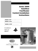
The dryer fan and heater controls featuring: 1-pressure regulator, 2-low-fire
control valve, 3-high pressure solenoid, 4-low pressure solenoid, 5-high-
low fire thermostat (assembly includes thermometer), 6-fuel supply line, 7-
LP solenoid or supply ball valve(NG) and 8-air pressure switch.
3
4
2
1
7
5
8
6
START the fan, and then turn the
HEATER switch to ON. Turn ON the
fuel supply, and the burner should
BURNER TEST FIRE
BURNER SAFETY
To check the burner safety function,
first make sure the main GAS
VALVE is OFF. Turn the FAN switch
ON and allow the fan to start. Then,
turn the HEATER switch ON. The
dryer will shut down after 20 seconds.
The safety message, "Burner 1 warn-
ing flame not detected" will appear.
Bump the FAN switch and observe
the fan rotation. The fan should run
counterclockwise. Sometimes on
three phase models all motors will
run backwards. They can easily be
reversed by interchanging the two
of three power supply wires. Re-
verse the two outside wires, L1 and
L3, and leave the middle one in the
same position.
Note: If the dryer is empty, the
burner will not operate. The fans
cannot create enough static pres-
sure to engage the air switch. You
will receive a loss of airflow message.
FAN SWITCH
ignite after a short purge delay of ap-
proximately 10 seconds. Gas pres-
sure should be shown on the gauge.
At this time adjust the BURNER
HIGH-LOW FIRE THERMOSTAT to
200°F, causing the burner to oper-
ate on high-fire. The thermostat is
located on the front left side of the
dryer. Observe the gas pressure on
gauge, and turn the thermostat to
its MINIMUM SETTING, causing the
burner to cycle into low-fire. As the
burner thermostat is turned down
the gas pressure should also show
a noticeable drop, indicating that the
high-fire solenoid is closed and the
burner is being supplied with less
gas through the low-fire control
valve. At this time set the high-
fire and low-fire pressure settings.
Use the PRESSURE REGULATOR
for high-fire and the BALL VALVE
for low-fire. The thermostat should
cycle between high and low, ap-
proximately 4 to 5 times per minute.
Approximate settings should be:
LP Gas High-Fire 6-15 lbs.
Low-Fire 2-6 lbs.
Natural Gas High-Fire 6-10 lbs.
Low-Fire 1-3 lbs.
If the burner remains on high-
fire and does not cycle, INCREASE
the regulator setting on the propane
models, or the supply valve on the
natural gas models in order to reach
the thermostat setting. If the
burner remains in low-fire and does
not cycle, slightly DECREASE gas

17
DRYER PRE START CHECKS
STAGED BATCH CHECK
DRYER SHUTDOWN
To shutdown the dryer, first CLOSE
the FUEL SUPPLY VALVE at the
tank or valve along the fuel line. If
the burner is operating, let the dryer
run out of fuel, and it will shutdown
automatically due to loss of flame.
CLOSE the FUEL VALVE at the
dryer, and press the DRYER
POWER STOP button. Turn OFF
the safety disconnect handle on
the front of the power box, and turn
OFF the main POWER to the dryer.
In case of emergency push the dryer
POWER STOP button. The fan,
burner and all augers will stop im-
mediately.
EMERGENCY
VALVE to allow fuel flow to the
dryer, if so equipped. Turn the
LOAD switch to AUTO and UN-
LOAD switch to 1 SPEED. Push
the DRYER POWER START but-
ton and the controller will sequen-
tially start all dryer components in
their proper order. If any switches
are not in their correct position for
staged batch operation, the dryer
will indicate improper switch posi-
tion, and will not start until the
switches are in the proper position.
After starting, all batch timers will
time down in sequence. When the
unload cycle is complete the tim-
ers will automatically reset to their
original settings, and start the dry
timer again.
To check the staged batch opera-
tion, turn the CONTROL POWER
switch to the ON position. Press the
RESET button, OPEN the main
FUEL SUPPLY VALVE at the tank
on an LP dryer or valve in the fuel
supply line on a natural gas dryer.
Turn the DRYING MODE switch to
the STAGED BATCH position.Turn
ON the electric SHUT OFF
pressure with the LOW-FIRE CON-
TROL VALVE. If the gas pressure
is decreased too much a popping or
fluttering sound will be heard. Also,
anytime the high pressure side is
adjusted the low pressure side
needs to be checked.
All dryer functions should be checked before operation each season.

18
DRYER START UP
1. Turn the CONTROL POWER
switch to ON.
2. After the date and time appear
on screen, press the RESET
button.
3. Push the dryer POWER START
switch.
4. OPEN the main FUEL SUPPLY
VALVE on the tank if using LP
gas, or OPEN the FUEL SUP
PLY LINE if using natural gas.
CONTINUOUS FLOW
OPERATION
CONTINUOUS FLOW AND CONTINUOUS BATCH START UP PROCEDURE
Turn ON the electric SHUTOFF,
Maxon valve (if so equipped), or
OPEN the manual SHUTOFF
valve to allow fuel flow to the
dryer.
5. Turn the DRYING MODE switch
to CONTINUOUS FLOW.
6. The dryer should already be
filled with grain. Turn the
LOAD AUGER switch to the
AUTO position. In both the auto
and manual positions the dryer
grain level switch will automati-
cally keep the dryer full of grain.
In the auto position the dryer will
shut down after a preset time
period on the out of grain timer.
7. Turn the FAN switch to ON. The
fan will start, and the switch will
light up when airflow is detected.
8. Start the burner by turning the
HEATER switch to ON. After
purging for approximately 10
seconds the burner will fire, and
the heater switch will light up.
This indicates that the flame
sensing circuit is sensing burner
flame. For information concern-
ing burner adjustment see the
pre start section of this manual.
9. Operate the heaters to dry grain
for 6-7 minutes per point of
moisture to be removed with the
plenum temperature set at
180°F. Example: Shelled corn
starts with 25% moisture and
be displayed on the LCD. If all
are found safe the controller will
allow the electronic FUEL SHUT
OFF valve to be manually
OPENED (if so equipped), and
the DRYING MODE switch will
light up, indicating that the dryer
is ready to be started.
5. Move the LOAD AUGER switch
to MANUAL, and push the dryer
POWER START switch. The
top auger will immediately start,
and the LOAD AUGER switch
will light up. If additional grain
handling equipment is wired to
the dryer it will also start imme-
diately.
6. When the dryer is full of grain
the top auger will stop auto-
matically, and any grain han-
dling equipment wired to the
dryer will also stop.
At the beginning of each harvest and
before filling the dryer with grain
make sure to inspect the dryer for
rodent damage, proper belt and
chain tension and missing or dam-
aged safety shields. Test operate
the dryer using the prestart check
procedures located on pages 14-17.
1. Before attempting to operate the
dryer make sure that all safety
shields are in place, all plenum
bottom closure panel doors
are closed, all rear access
doors are closed and all per-
sonnel are clear of the grain
dryer and grain handling ma-
chinery.
2. Turn all SELECTOR switches
on the control panel to the OFF
position.
3. Turn ON the electric POWER
supply to the dryer, and move
the safety disconnect handle
mounted on the dryer's upper
power box to ON.
4. Turn the CONTROL POWER
switch to ON. The switch will
light up. A copyright message,
model number, total running
time in hours and minutes, cur-
rent date and time will appear.
At this point the controller will
lock out all other dryer functions.
Once the date and time appear,
press RESET, and the dryer will
perform its safety circuit checks.
If a fault is found the cause will

19
DRYER START UP
the final moisture content is to
be 15% (10% removal). Using
the all heat dryeration process,
the estimated drying time is 60
minutes (10 x 6).
10. While operating the dryer adjust
the METERING ROLL dials to
the recommended settings. See
the chart on page 00.
11. To move grain through the dryer
turn the MOISTURE CONTROL
switch to ON. The switch will
light up.
Note: When the UNLOAD switch is
in the 2 SPEED position, and the
MOISTURE CONTROL THERMO-
STAT switch is OFF, the speed of
the metering rolls can be manually
adjusted by turning the HIGH
SPEED METERING ROLL dial.
Turning the dial clockwise will IN-
CREASE the grain discharge rate,
counterclockwise will DECREASE
the discharge rate. (The numbers on
the speed dials indicate the percent-
age of full speed.)
12. At the end of the start-up pe-
riod, start the flow of grain out
of the dryer. Turn the UNLOAD
switch to the 2 SPEED posi-
tion. The bottom auger and
metering roll will immediately
start, and the unload switch will
light. If additional grain han-
dling equipment is utilizing the
unload auxiliary overload sup-
plied with the dryer, this equip-
ment will also immediately
start.
13. To shut the dryer down, CLOSE
the FUEL SUPPLY VALVE at
the fuel tank or fuel source. Let
the dryer run until the fuel sup-
ply lines drain, and the dryer
automatically shuts down due to
loss of flame. CLOSE the FUEL
valve at the dryer. Press the
DRYER POWER STOP button.
Turn OFF the dryer's SAFETY
DISCONNECT handle. Turn
OFF the MAIN POWER supply
to the dryer.
14. In case of emergency push the
dryer STOP button. The fan,
burner and all augers will stop
immediately.
Note: The Electronic Monitoring
Control System can be used to au-
tomatically start the dryer. Place all
the control panel SELECTOR
switches in the PROPER POSI-
TION, and OPEN the electric FUEL
SHUT OFF valve before PRESSING
the DRYER POWER START button.
The controller will start all dryer com-
ponents in their proper order.
gas or the valve in the FUEL
SUPPLY LINE if using natural
gas. Turn ON the ELECTRIC
SHUT OFF, Maxon valve (if so
equipped), or OPEN the manual
SHUT OFF valve to allow fuel
flow to the dryer.
5. The dryer should already be
filled with grain. Turn the LOAD
AUGER switch to AUTO. In both
the auto and manual position,
the grain level switch will auto-
matically keep the dryer full of
grain. In the auto position, the
dryer will shut down after the
preset time period on the OUT
OF GRAIN TIMER, or if the
grain flow to the dryer is inter-
rupted.
6. Turn the FAN switch to AUTO.
The fan will start, and the switch
will light up when airflow is de-
tected.
7. Start the burner by turning the
HEATER switch to AUTO. Af-
ter purging for approximately
10 seconds the burner will fire,
and the heater switch will light
up indicating that the flame
sensing circuit is sensing
burner flame. For information
concerning burner adjustment
see the pre start section of this
manual.
8. To properly set the correct dry,
cool and unload time for various
moisture content grains. See the
chart on page 00.
1. Turn the CONTROL POWER
switch to ON.
2. Make sure the DRYING MODE
switch is turned to STAGED BATCH.
3. After the date and time appear,
PRESS the RESET button.
4. OPEN the main FUEL SUPPLY
VALVE on the tank if using LP
STAGED BATCH
OPERATION

20
DRYER START UP
button. The controller will start
all the dryer components in their
proper order. If any of the se-
lected switches are improperly
positioned for staged batch dry-
ing, the display will indicate the
proper switch position, and will
not allow the dryer to operate
until the position of the switch is
corrected.
14. To shutdown the dryer, CLOSE
the FUEL SUPPLY valve at the
fuel tank or fuel source. If the
burner is operating, let the dryer
run out of fuel causing an auto-
matic shutdown due to a loss of
flame. CLOSE the FUEL VALVE
at the dryer, and press the dryer
POWER STOP button. Turn
OFF the dryer's main CIRCUIT
BREAKER located on the front
of the power panel. Turn OFF
the MAIN main POWER SUP-
PLY to the dryer.
15. In case of an emergency press
the dryer POWER STOP button.
The burner, fan and all augers
will stop immediately.
start automatically during the
unload cycle of the dry-cool-
unload mode, along with any
grain handling equipment that
is wired to the dryer. The
speed at which the metering
rolls operate during the unload
cycle is adjusted by using the
HIGH SPEED METERING roll
dial. Turning the dial clockwise
will INCREASE the grain dis-
charge rate, and counterclock
wise will DECREASE the dis-
charge rate.
12. To control the length of the dry
cycle using only the dry time
setting programmed into the
system, turn the MOISTURE
CONTROL setting to OFF. To
use the automatic moisture con-
trol so that the dry time is deter-
mined, not only by the dry time
setting, but also by the moisture
content of the drying grain, turn
the MOISTURE CONTROL
switch to ON.
13. To start the drying operation
push the dryer POWER START
9. If the dryer is being operated in
all heat, turn the FAN switch to
ON. In this position the fan will
run continuously during the dry,
cool and unload stages of the
staged batch operation. If the
dryer is being operated in the
dry and cool mode, the preferred
position for the FAN switch is the
ON position, so the fan will run
continuously. If desired, the fan
can be turned off during the un-
load cycle of the dry-cool-unload
sequence by turning the FAN
switch to AUTO.
10. If the dryer is being operated in
all heat, turn the HEATER
switch to ON. The burner will
operate whenever the fan is
operating. If the dryer is being
used in dry and cool, turn the
HEATER switch to AUTO and
the burner will automatically
shutdown during the cooling and
unloading cycles.
11. Turn the UNLOAD switch to the
1 SPEED position. The bottom
auger and metering rolls will
Fan Setting
Auto
Auto
On
On
Fan Function
Fans stay on during dry and cool
cycle only
Fans stay on during dry and cool
cycle only
Fans are on continuously
Fans are on continuously
Heater Function
Burners stay on during dry timer cycle
only
Burners stay on during dry and cool
Burners are on continuously
Burners shut down at the end of the
dry cycle
Heater Setting
Auto
On
On
Auto
FAN & HEATER SWITCH SETTINGS
At the end of the dry cycle in staged batch, the fans and heaters will continue running if in the Auto-Auto setting, until the preset tempera-
ture on the moisture control thermostat is reached.
/