Page is loading ...

owner’s manual
Crest Audio Inc.
100 Eisenhower Dr., Paramus NJ 07652 USA
TEL: 201.909.8700 FAX: 201.909.8744
http://www.crestaudio.com
*A4400076*
v. 1.0 4/29/98
Ch A Ch B
-
80
-
30
-
15
-
10
-
6
-
3
-
1
ØdB
-
80
-
30
-
15
-
10
-
6
-
3
-
1
ØdB
8002
Professional Power Amplifier
Status
Signal
ACL
8002 power amplifier

1
Save the carton and packing materials!
Should you ever need to ship the unit,
use only the original factory packing.
For replacement packaging, call Crest Audio’s
Customer Service Department directly.
2
Read all documentation before
operating your equipment. Retain all
documentation for future reference.
3
Follow all instructions printed on
unit chassis for proper operation.
4
Never hold a power switch in the
on-position, if it won’t stay there
by itself!
5
Do not use the unit if the electrical
power cord is frayed or broken.
The power supply cords should be
routed so that they are not likely to be
walked on or pinched by items placed
upon or against them.
6
Always operate the unit with the
AC ground wire connected to the
electrical system ground. Precautions
should be taken so that the means of
grounding of a piece of equipment is not
defeated
.
7
Damage caused by connection to
improper AC voltage is not covered
by any warranty. Mains voltage must be
correct and the same as that printed on
the rear of the unit.
8
Do not ground any hot (red) terminal.
Never connect a hot
(red) output to
ground or to another hot (red) output!
9
Power down and disconnect units
from mains voltage before making
connections.
0
Do not drive the inputs with a sig-
nal level greater than that
required to enable equipment to
reach full output.
¡
Do not run the output of any ampli-
fier channel back into another
channel’s input.
Do not parallel- or series-connect
an amplifier output with any
other amplifier output.
Crest Audio is not responsible for damage
to loudspeakers for any reason.
Ô
Do not connect the inputs or out-
puts of amplifiers to any other
voltage source: such as a battery,
mains source, or power supply, regard-
less of whether the amplifier is turned
on or off.
£
Connecting amplifier outputs to
oscilloscopes or other test equip-
ment while the amplifier is in bridged
mono mode may damage both the
amplifier and test equipment!
¢
Do not spill water or other liquids
into or on the unit, or operate the
unit while standing in liquid.
ˆ
Do not block fan intake or
exhaust ports.
Do not operate equipment on a
surface or in an environment
which may impede the normal
flow of air around the unit: such as
a bed, rug, weathersheet, carpet, or
completely enclosed rack.
§
If the unit is used in an extremely
dusty or smoky environment: the
unit should be periodically “blown free”
of foreign matter.
¶
Do not use the unit near stoves,
heat registers, radiators, or other
heat producing devices.
ƒ
The power cord of equipment
should be unplugged from the out-
let when left unused for a long peri-
od of time.
Service Information
Do not remove the cover!
Removing the cover will expose you to
potentially dangerous voltages.There are
no user serviceable parts inside.
Equipment should be serviced by
qualified service personnel when:
A. The power supply cord or the plug has
been damaged.
B. The equipment has been exposed to rain.
C. The equipment does not appear to oper-
ate normally, or exhibits a marked change in
performance.
D. The equipment has been dropped, or the
enclosure damaged.
To obtain service:
contact your nearest Crest Audio
Service Center, Distributor, Dealer,
or Crest Audio at 201.909.8700
USA
or visit www.crestaudio.com for addi-
tional information.
email techserve
@crestaudio.com
This symbol is used to alert
the operator to follow important
procedures and precautions
detailed in documentation.
This symbol is used to warn operators
that uninsulated “dangerous voltages”
are present within the equipment enclosure
that may pose a risk of electric shock.
important precautions

p. 1
table of contents
1
2
3
4
5
6
7
how to use this manual
p.2
introduction
p.3
installation
p.5
unpacking
mounting
cooling and ventilation
powering
maintenance
features overview
p.11
front panel
rear panel
operation modes
p.17
stereo
parallel
bridged
connections
p.21
input
output
safety
p.27
tourclass protection
precautions
user responsibility
service and support
p.33
support
contact us
registration
specifications
p.36
block diagram
p.37
wire gauge charts
p.38
a
b
c
contents
appendixes

p. 2
Pro II owner’s manual
how to use this manual
1
conventions
terms
official Crest Audio features and
each indicator or control on the amplifier will appear as: terms
actions
specific actions or selections the user can execute will appear as: actions
tasks
are broken down into steps 1
2
3
warnings
indicators
tips
see
see—refers to other sections of the manual containing
supplementary information on the current topic or a related issue
note
note—supplimentary feature information
Prefered methods.
Helpful hints.
Feature insights.
+
Procedures not to attempt.
Issues or hazards to keep
in mind when operating
the equipment.
a
What to look for on
the equipment display.
Alerts, indicators, or
prompts that may appear.
®

p. 3
introduction
1
welcome
Congratulations on your purchase of a new Pro II Series professional
power amplifier, and thank you for your confidence in Crest Audio prod-
ucts.You are among the growing number of audio professionals who have
made Crest Audio one of the world’s leading suppliers of professional and
commercial/industrial audio systems.
For your safety, please read the Important Precautions section before
installing and operating the amplifier. The Crest Audio Pro II Series is based
on the same advanced circuit topologies that have made Crest’s original
Professional Series amplifiers the choice of touring professionals world-
wide. Pro II Series amplifiers are designed for high operating efficiency and
accurate sonic performance across the full audio bandwidth, even under
stressful conditions.
The Pro II Series heralds a major advance in amplifier design from Crest
Audio, providing the extreme reliability and hallmark sonic accuracy for
which Crest products are famous, in a rugged package but at only half the
weight of previous models of similar power.These dramatic weight savings
are made possible by PowerLok, a radical new power-supply technology
that provides significant performance and flexibility advances over conven-
tional designs.PowerLok is Crest Audio's unique implementation of Power
Factor Correction, which allows current to be drawn throughout the
entire cycle of the
AC line-frequency, providing maximum output power,
while drawing significantly smaller peak currents from the
AC line.
Compared with an amplifier using a conventional power-supply, PowerLok
requires less peak power to produce identical output power, and because
PowerLok's current peaks are smaller, a Pro II amplifier can be serviced by
a lower-rated breaker than a conventional amplifier of similar wattage. See
separate literature for full details on the benefits of PowerLok technology.
In order to maintain strict quality assurance standards, all Crest Audio
power amplifiers are built in our state-of-the-art
USA manufacturing facili-
ty. Internal components are the finest available and key sub-assemblies are
pre-tested before final assembly. Each amplifier is “burned in” and thor-
oughly tested
(using precision audio test equipment) before shipping. In
addition, all Pro II Series amplifiers incorporate Crest’s exclusive TourClass
protection features to safeguard both internal circuitry and connected
loudspeakers.
This proven combination of advanced design, quality construction, and
comprehensive circuit protection is your guarantee of fail-safe reliability.
You can depend on consistent, stable performance even when your Pro II
Series amplifier is subjected to punishing extremes in the most demanding
fixed or mobile sound reinforcement applications.

p. 4

p. 5
installation
2
unpacking
mounting
cooling and
ventilation
powering
maintenance
/
what to do with the shipping carton
/
proper rack-mounting technique
/
keeping the amplifier cooled
/
grounding the amplifier
/
required AC line voltages
/
routine maintenance practices

Pro II owner’s manual
p. 6
installation
2
unpacking
Please inspect the amplifier carefully immediately after unpacking. If you find
any damage, notify your supplier/dealer immediately. Only the shipper may
file a damage claim with the carrier for damage incurred during shipping. Be
sure to save the carton and all packing materials for the carrier’s inspection.
If the packing materials are in good condition, please save them.
If you ever need to ship the unit back to Crest Audio or an authorized ser-
vice center, you should use only the original factory packing.
For replacement pack-
aging, call Crest Audio’s
Customer Service
Department directly.
see—service and support
+

p. 7
installation
2
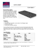
mounting
All Pro II Series amplifiers mount in standard 19-inch racks. Four front-panel
mounting holes are provided on each amplifier. Rear mounting ears give addi-
tional support, and use of rear supports is highly recommended in all mobile
and touring sound systems. Handles are fitted standard.
Ch A Ch B
-
80
-
30
-
15
-
10
-
6
-
3
-
1
ØdB
-
80
-
30
-
15
-
10
-
6
-
3
-
1
ØdB
8002
Professional Power Amplifier
Status
Signal
ACL
front
height
5.25"/
133mm
front width 19"/483mm
8002 shown
8002 shown
35mm
rear width 17"/432mm (19”/483mm to rack ears)
depth 18"/457mm
rear
height
5.25"/
133mm

Pro II owner’s manual
p. 8
installation
2
To ensure optimum
cooling of the amplifier,
periodically clean its fan
filters. These are removable
without tools.
Make certain that there is
enough space around the
front of the amplifier
to allow the heated air to
escape. If the amplifier is
rack-mounted, do not use
doors or covers on the front
of the rack; the exhaust air
must not be impeded
In racks with closed backs:
for every four amplifiers,
allow at least one standard-
rack-space opening in the
front of the rack.
a
cooling and ventilation
Pro II Series amplifiers use a twin-tunnel forced-air cooling system to main-
tain a low, even operating temperature.
Drawn in by dual 105
CFM (cubic feet-per-minute) DC fans on the rear panel,
air flows through the cooling fins of the channel heat-sinks,dissipating power
transistor heat
—then exhausts through the front panel slots.
Heat sink temperature-sensing circuits control the “intelligent” variable-
speed fans. Fan speed increases only as required by heat-sink temperatures
—
keeping fan noise to a minimum.
Under extreme thermal load, the fans will force a very large volume of air
through the heat sinks. If either heat-sink surpasses the maximum allowed
temperature, the sensing circuit will open the output relay, disconnecting the
load from that channel.
If the power supply overheats, another sensing circuit opens both channel
output relays, until it has cooled to a safe temperature.

p. 9
installation
2
powering
Unless otherwise specified when ordered, Pro II amplifiers shipped to cus-
tomers are configured as follows:
North America 90 –255
VAC
@
50–60Hz
Europe 180–255 VAC
@
50–60Hz
Asia 180–255 VAC
@
50–60Hz
Australasia 180–255 VAC
@
50–60Hz
South America 90–255 VAC
@
50–60Hz
Japan 90–255 VAC
@
50–60Hz
maintenance
A Pro II Series amplifier requires no routine maintenance other than the
occasional cleaning or replacement of the fan intake filters on the rear of the
amplifier.
(This operation does not require any tools.) Filters must be kept
clear and clean to ensure proper ventilation through the unit.
If the amplifier is used in an extremely dusty or smoky environment, the fil-
ter should be cleaned or changed frequently and the unit should be period-
ically “blown free”
(using compressed air) of any foreign matter that may have
penetrated the filter.
Users will not need to make any internal adjustments to the amplifier dur-
ing its lifetime. There are no user-serviceable parts or adjustments that
require opening the power amplifier.
Always turn off and dis-
connect the amplifier from
mains voltage before mak-
ing audio connections.
As an extra precaution, have
the attenuators turned down
during power-up.
a
Cover removal exposes
the risk of shock, so refer
all servicing to qualified
service technicians autho-
rized by Crest Audio.
a

p. 10

p. 11
features overview
3
front panel
rear panel
/
location of connectors and controls
/
legend of panel symbols

Pro II owner’s manual
p. 12
features overview
3
Ch A Ch B
-
80
-
30
-
15
-
10
-
6
-
3
-
1
ØdB
-
80
-
30
-
15
-
10
-
6
-
3
-
1
ØdB
8002
Professional Power Amplifier
Status
Signal
ACL
8002 shown
1 2 3
8
4
7
5
6

p. 13
features overview
3
front panel
1
Rack Mounting Ears
Two front-panel mounting holes are provided on each mounting ear.
2
Rack Handles
3
Fan Outlet Grills
Pro II Series amplifiers are cooled by two, rear-mounted fans. Cool air
flows over the heat sinks and exhausts through the front grills. Make
sure these outlets remain clear to allow unrestricted airflow.
4
Signal LED
A variable-intensity LED that illuminates to indicate that a signal (above
a minimum threshold
) is present at the amplifier input,and that the sig-
nal is being amplified.
5
Input Attenuators
Two input attenuators adjust level for their respective amplifier chan-
nels. In Bridged Mono mode, the channel A attenuator controls signal
level.
6
Status LED
A bi-color LED.When green, it indicates that AC power is connected
and the amplifier is turned on.When red,the channel is in
Protect mode
(speakers disconnected by output relay).
7
ACL LED
Illuminates at the clipping threshold. Continuous illumination also indi-
cates that
ACL ACTIVE CLIP LIMITING protection circuitry is engaged.
8
AC Power Switch/Circuit Breaker
Pro II Series amplifiers have a front-panel combination AC switch/cir-
cuit breaker.
(No fuses are used.) If the switch shuts off during normal
use, push it back to the on-position once. If it will not stay on, the ampli-
fier needs servicing.
note—all LEDs are one per channel
Never try to hold the
circuit breaker/power
switch in the on-position,
if it won’t stay there itself!
a

Pro II owner’s manual
p. 14
features overview
3
rear panel
1
Output Connectors
Pro II Series power amplifiers are supplied with both high-current five-
way binding posts and Speakons installed. Binding posts: one pair per
channel. Speakons: one connector per channel, plus a third connector
configured for bridged-mono operation.
Connection to the binding posts can be made with bare wire or spade
lug terminations. Make connections to both the channel A and channel B
terminals for Stereo or Parallel mode, or a single connection across the
red
(hot) terminals only of channels A and B for Bridged Mono mode.
Using cables terminated with Speakon connectors, attach to both the
channel A and channel B connectors for Stereo or Parallel mode, or to
the Bridged mode connector/s for Bridged Mono mode.
see—operation modes
2
Mode Selection Switch
This recessed, three-position switch configures the amplifier for Stereo,
Parallel or Bridged Mono mode operation. Amplifiers are factory-config-
ured for Stereo mode.
see—operation modes
Do not adjust the mode
selection switch while the
amplifier is turned-on.
a
rear panel legend
+
1
3-
2+
A
A
B
B
A
A
B
AB
A
GAIN
Ø
dBu
40x
20x
XLR Pin +
2 3
XLR Pin +
2 3
GAIN
Ø
dBu
40x
20x
A
B
B
A
+
+
+
B
A
A
B
input connection
XLR
connector polarity
TRS connector polarity
bridged mono mode
parallel mode
stereo mode
chassis ground lifted-position
chassis ground grounded-position
gain select
XLR pin 2/3 hot (+)
output connection
speakon output
channel A stereo/parallel
channel B stereo/parallel
bridged mono
five-way binding post
channel A stereo/parallel
bridged mono
channel B stereo/parallel
1
2
3
8
4
7
5
6
8002 shown

p. 15
features overview
3
rear panel
3
Female Balanced XLR Input Connectors
4
Male Balanced XLR Input Connectors
These connectors accept input signals on balanced male and female
XLR input plugs. Connectors for each channel are in parallel; any
unused
XLR connectors may be used for daisy-chaining input connec-
tions to other amplifiers.
In Parallel and Bridge Mono mode a signal applied to channel A’s input
connectors will appear also at channel B’s.
5
Input Sensitivity/Gain Switch
The Pro II Series amplifiers come standard set to x40 gain.
The Input Sensitivity/Gain switch allows the user to select either
.775
(0dB) sensitivity, x40, or x20 gain.
6
Fan Inlet Ports and Filters
Cooling air enters the amplifier through the fan inlet ports located on
the rear of the amplifier chassis.Be sure not to block these ports when
installing the amplifier or other associated equipment. Air must flow
unimpeded. Fan filters
(removable without tools) are provided to min-
imize entry of dust and dirt.
7
Input XLR Polarity Switch
Pro II Series amplifiers are supplied standard with the XLR configured
as Pin 2 hot
(
+
). Use the XLR polarity switch to change this setting to
Pin 3 hot
(
+
) if desired.
8
Signal Ground-Lift Switch
The recessed signal ground-lift switch electrically connects signal
ground to the chassis/
AC ground. This switch is factory-set to the
ground position
(bottom). The top position lifts the amplifier’s signal
ground. In a properly designed system
(for safety purposes and to min-
imize noise
), amplifiers should be connected to ground through the AC
line cord.
Whenever possible, the signal source equipment should share the
same
AC ground as the amplifier. In some cases this may not be possi-
ble, and a ground loop results. If this happens, the first step is to move
the ground-lift switch to the lifted position
(top). In this position,the sig-
nal ground is lifted and completely isolated from the chassis/
AC
ground. Do not change the switch to the lifted position if the amplifi-
er and the signal source equipment are on the same
AC ground.
Should the ground loop problem persist after the ground-lift switch
has been set to the lifted position, then the shield on balanced input
lines should be grounded at one end only
(usually the signal source).
Never connect a hot (red)
output to ground or to
another hot (red) output!
a

p. 16

p. 17
operation modes
4
stereo
parallel
bridged
/
choosing the appropriate mode
/
switching between operation modes
/
keeping the amplifier cooled
/
special considerations when using bridged mode

Pro II owner’s manual
p. 18
operation modes
4
mode selection
The three-position,recessed Mode Select switch (located on the rear panel)
configures the amplifier for Stereo, Parallel or Bridged mode. Amplifiers are
factory-configured for Stereo mode.
stereo
In Stereo mode, both channels operate independently, with their input atten-
uators controlling their respective levels.Signal at Channel A’s input produces
output at Channel A’s output,while signal at Channel B’s input produces out-
put at Channel B’s output. Recommended minimum nominal load impedance
for stereo operation is 2 ohms per channel. Either the male or female
XLR
inputs may be used.
parallel
When set to Parallel mode, a signal applied to Channel A’s input will be ampli-
fied and appear at outputs for both Channels A and B. Either the male or
female
XLR input on Channel A may be used. Individual channel attenuators
control signal level.
bridged
Bridged mode straps both amplifier channels together to make a very pow-
erful, single-channel monaural amplifier. One channel “pushes” and the other
“pulls” equally, doubling the power over that of either channel alone. Signal is
applied to the Channel A input only. Channel A’s attenuator is used to con-
trol signal level. Either male or female
XLR input may be used.
The channel B input connectors (male or female
XLR) may be used to daisy-
chain the channel A signal when in parallel or bridged mono mode. Use
extreme caution when operating the amplifier in Bridged mode. Never
ground either side of the speaker cable when the amplifier is in Bridged
mode; both sides are “hot.”
If an output patch panel is used, all connections must be isolated from each
other and from the panel.The recommended minimum nominal load imped-
ance in the Bridged mode is 4 ohms, which is the equivalent to driving both
channels separately at 2 ohms.
see—connections for examples of mode-specific wirings
Driving bridged loads
of less than the recom-
mended minimums will
activate the IGM circuitry,
resulting in a loss of power,
and may also lead to a
thermal protect condition.
a
Connecting amplifier
outputs to oscilloscopes
or other test equipment
while the amplifier is
in bridged mode may
damage both the amplifier
and test equipment!
a
/