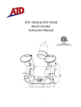
Lininshall BG8/915 User manual

Type
User manual

This manual is also suitable for

Lininshall BG8/915 is a bench grinder, belt, and disc grinder that can be used for various grinding applications. With a powerful 750W motor, it can handle demanding tasks efficiently. The BG8/915 features an 8-inch grinding wheel and a 36-inch grinding belt, providing ample surface area for grinding and shaping materials. Additionally, it comes with a 7-inch grinding disc, allowing you to perform disc grinding operations as well. It is equipped with adjustable tool rests to support the workpiece during grinding, ensuring precise and controlled results.

Lininshall BG8/915 is a bench grinder, belt, and disc grinder that can be used for various grinding applications. With a powerful 750W motor, it can handle demanding tasks efficiently. The BG8/915 features an 8-inch grinding wheel and a 36-inch grinding belt, providing ample surface area for grinding and shaping materials. Additionally, it comes with a 7-inch grinding disc, allowing you to perform disc grinding operations as well. It is equipped with adjustable tool rests to support the workpiece during grinding, ensuring precise and controlled results.

THE NAME FOR GRINDING
Instruction Manual
Bench Grinding Series
Models BG6, BG8, BG8/915, BG10
Australia:
Garrick Herbert Pty Ltd
460-462 The Boulevarde
Kirrawee, Sydney, NSW
Ph: 02-9545 6633
www.linishall.com.au
New Zealand:
R.R. Bramley & Co Ltd
184 Marua Rd
Mt Wellington, Auckland
Ph: 09-579 2036
www.bramley.co.nz
USA:
Garrick USA LLC
5455 West 6th St
Winona, MN 55987
Ph: 800-749 1064
www.linishall.com
Model BG8
Model BG8/915
513
THE NAME FOR GRINDING
Table of Contents
Safety Warnings .................................................................................3
The correct use & care of grinding wheels..........................................4
Model Specications ..........................................................................5
Unpacking & checking contents..........................................................6
Assembly Instructions (Models BG6 & BG8)......................................8
Assembly Instructions (Model BG10 & BG8/915).............................10
Genuine Parts and Accessories.........................................................11
Warranty and Service........................................................................12
2
3
This instruction manual should be read before assembling or using your bench grinder.
All instructions should be strictly adhered to so the safety of yourself and others is
protected. Keep this manual handy for future reference.
1) The grinder and all accessories are designed and manufactured to be used only by persons
trained in their proper use and only for their intended purpose. They are not intended for lengthy
continuous usage. i.e. Turn ON, Sharpen Tool, Turn OFF
2) Follow assembly instructions closely and do not plug machine into mains power until all
guards are rmly attached in the correct position (and remain so) and all parts are securely
tted.
3) Make sure the grinder is securely clamped or bolted to your workbench or pedestal stand
and that the workbench or stand is securely attached to the oor.
4) Make sure the switch is in the off position before connecting to mains power. Any
adjustments or maintenance should be made with the grinder unplugged from its power source.
Ensure any keys or wrenches are removed.
5) Ensure the machine is electrically grounded. The plug must match the outlet and must never
be modied in any way. Long extension leads should not be used due to voltage drop.
6) Ensure the work area is clean and well lit. Do not use in wet or damp conditions. Keep
children and bystanders away.
7) Eye protection should always be used. Normal optical spectacles are not sufcient. Neck ties
should be removed and sleeves rolled up. Long hair and loose clothing should be secured. Do
not wear gloves. Non slip footwear or anti-slip footwear is recommended. Hearing protection
should be used for prolonged use.
8) Never use the grinder if impaired by tiredness, alcohol, drugs or medication.
9) The action of grinding will produce dust and/or particles from both the material being ground
and the grinding wheel or belt. Depending on the product being ground, these particles & dust
may be harmful to your health. Ensure the area is well ventilated and that suitable dust mask or
breathing apparatus is used.
10) Never leave a running grinder unattended. Do not leave the work area until it has come to a
complete stop.
11) Your grinder should only ever be serviced by a qualied repair person. To ensure safety
integrity, we recommend using only genuine Linishall
TM
replacement parts or accessories.
12) Familiarise yourself with the section about correct use of grinding wheels
4
The correct use & care of grinding wheels
Always use the correct type of grinding wheel according to the model of grinder
and your intended use. Do not use grinding wheels as a cutting disc.
During normal use, grinding wheels will wear by becoming chipped, worn at the
edges, grooved, out of balance and clogged by foreign material. This can be
rectied by use of the wheel dresser tted on the top of the grinder. Rest the
cast face of the dresser on the tool rest and bring the wheels into contact with
the wheel (whilst running). Move the dresser backwards & forwards (left and
right) accross the wheel until a fresh, at, square face is exposed on the wheel.
Sometimes a wheel may be cracked. Never under any circumstances use
a cracked wheel for grinding as it could ‘explode’ causing serious injury
to the operator. Wheels can be tested for cracks with the “Ring Test”. This in-
volves hanging a wheel (removed from the grinder) by a piece of string passed
through its centre hole. The wheel can then be tapped with a piece of scrap
wood or similar and if OK the wheel will “ring”. If there is a defect it will sound
as a “thud”. The defect may not be able to be detected by visual inspection. It is
important that a wheel failing the ring test be permanently discarded.
The Linishall
TM
grinders are supplied with general purpose grinding wheels.
For specialised grinding applications, such as carbide grinding, please consult
your local specialist abrasive distributor.
Always grind by using the outer diameter edge of the grinding wheel. Never
grind on the side of the grinding wheel. This can cause the wheel to shatter.
Do not use excessive force on the grinding wheel. If it is not removing material
fast enough, it is either clogged (requiring cleaning with the wheel dresser as
above) or is not coarse enough. Choose the correct grit (coarseness) for the
job.
Always adjust the tool rest as close as possible to the wheel (maximum 3mm
gap) and do not attempt to grind objects that are to small to hold securely. Do
not use the workpiece to slow down the wheel after turning the grinder off.
5
MODEL SPECIFICATIONS
Model BG6 Bench Grinder
Wheel Size (DxWxBore) 6”x
3
/
4
”x
1
/
2
” (150x19x12.7mm)
Standard Wheel Grit 36 & 60
Thread (Nut) M12 x 1.75
Motor 450W (0.6HP) Single Phase
Voltage & Motor Speed
Aust / NZ USA
240v 50Hz 2,880rpm 120v 60Hz 3,450rpm
Lamp (Automotive type) 12v 6 watt
Model BG8 Bench Grinder
Wheel Size (DxWxBore) 8”x1”x
5
/
8
” (200x25x16mm)
Standard Wheel Grit 36 & 60
Thread (Nut) M16 x 2.0
Motor 750W (1.0HP) Single Phase
Voltage & Motor Speed
Aust / NZ USA
240v 50Hz 2,880rpm 120v 60Hz 3,450rpm
Lamp (Automotive type) 12v 6 watt
Model BG10 Bench Grinder
Wheel Size (DxWxBore) 10”x1”x
3
/
4
” (250x25x19mm)
Standard Wheel Grit 36 & 60
Thread (Nut) M20 x 2.5
Motor 900W (1.2HP) Single Phase
Voltage & Motor Speed
Aust / NZ USA
240v 50Hz 2,880rpm 120v 60Hz 3,450rpm
Lamp (Automotive type) 12v 6 watt
Model BG8/915 Bench, Belt & Disc Grinder
Bench Grinder Specications As per BG8 Bench Grinder
Grinding Belt Size 36” x 2” (915 x 50 mm)
Grinding Disc Diameter 7” (178mm)
6
Unpacking & checking of contents
Ensure carton is upright, carefully cut tape & open top aps of carton.
On models BG6, BG8 & BG8/915, some parts are located in recesses in the
polystyrene packing showing. Remove these, check off against the list below,
and set aside.
A
B
C
D
C
Model BG6
(A) 1 x Coolant Tray
(B) 1 x hardware pack containing:
2 x Toolrest Knob/Screw
2 x Toolrest Flat Washer
1 x Allen (Hex) Key
(C) 2 x (1ea) LH & RH Toolrest
(D) 1 x Wheel Dresser
Model BG8
(A) 1 x Coolant Tray
(B) 1 x hardware pack containing:
2 x Toolrest Knob/Screw
2 x Toolrest Flat Washer
1 x Allen (Hex) Key
(C) 2 x (1ea) LH & RH Toolrest
(D) 1 x Wheel Dresser
A
B
C
C
D
Model BG8/915
(A) 1 x Coolant Tray
(B) 1 x hardware pack containing:
1 x Toolrest Knob/Screw
1 x Toolrest Flat Washer
1 x Allen (Hex) Key
(C) 1 x LH Toolrest
(D) 1 x Wheel Dresser
A
B
D
C
7
For models BG6 & BG8, The whole carton should then be carefully turned
upside down (with aps open & out of the way) and then the carton can be lifted
off the grinder in its polystyrene packaging.
Turn the package back up the correct way, carefully cut the packing tape
along the join in the polystyrene packaging, and remove the top half of the
polystyrene from the grinder.
Open the plastic bag and remove & set aside the eyeshield packs.
The grinder can then be lifted out of the plastic bag & the polystyrene packing
and placed ready for assembly of loose components.
For model BG8/915, the top polystyrene packing can be removed, the
eyeshield pack located & set aside, and then the grinder can be lifted out of the
carton and made ready for nal assembly.
Model BG10 has polystyrene protection over the guards at each end. Remove
the upper polystyrene from each end and then the grinder can be lifted out of
the carton. (As the weight of the grinder is over 30Kg, it may require two people
to safely lift it)
Locate the following items packed loosely in the carton and set aside for nal
assembly:
1 x LH Toolrest
1 x RH Toolrest
1 x Wheel Dresser
1 x Coolant Tray
2 x Eyeshield Packs
1 x hardware pack containing:
4 x Hex Head Bolts M8x30
4 x Flat Washers M8
Your grinder is now ready for nal assembly as per the
instructions on Page 8.
Make sure it is placed securely on a rm workbench with
adequate room to work freely & safely
8
ASSEMBLY OF THE GRINDER
Models BG6 & BG8
1) The Wheel Dresser (A) clips into the plastic holder
on top of the grinder. There is also a place at the rear
of the plastic holder to store the allen (hex)key (B)
which is used to adjust the toolrests.
2) Use the allen (hex) key to loosen the Left Hand
toolrest arm (A), slide the arm forwards as far as it
can go in its slot, and retighten loosely.
Position the toolrest (C) against the front of the
toolrest arm as shown. There are radial grooves in
both the toolrest & arm which should be matched up
to achieve and lock the angle of the toolrest to the
grinding wheel (Usually this is set so that the top of
the toolrest is horizontal)
The toolrest knob/screw (B) can then be passed
through the toolrest casting and screwed rmly into
the arm.
Loosen the toolrest arm again (A) and slide the
assembly towards the grinding wheel until the gap
(D) between the toolrest and the grinding wheel is
no more than 3mm. Retighten the screw (A) rmly.
Rotate the grinding wheel slowly by hand to ensure it
can still run freely.
3) Repeat all steps in operation 2) for the Right Hand
Toolrest assembly.
A
A
B
B
C
D
9
4) Adjust the Spark Guards at the top of each grinding
wheel so that the gap between the spark guard &
the wheel is no more than 2mm. Rotate the grinding
wheel slowly by hand to ensure it can still run freely.
Note: As the wheels wear down, the spark guards
must be adjusted to maintain the 2mm gap.
5) The eyeshields should then be tted to the
guards as shown in the picture.
Note the position of the three washers (A) which
is important to allow the eyeshield to be adjusted
without creating a wear point of the clear plastic
against the sheetmetal of the guard.
The square section under the head of the bolt
ts into the square hole of the eyeshield to lock
the bolt when tightening the knob.
6) The coolant tray can then be tted to its bracket on
the base of the grinder, just under the switch.
7) The machine should then be securely bolted to a
solid workbench or the optional pedestal stand. The
workbench or stand must be securely attached to the
oor.
8) The last operation before use is to adjust the
worklight by its exible stalk to a suitable position.
A
10
ASSEMBLY OF THE GRINDER
Model BG10
Many of the assembly instructions are the same as for
BG6 & BG8 as liosted on pages 8&9 and we will refer
to them below
1) The Wheel Dresser clips into the plastic holder on
top of the grinder as for BG6/BG8.
2) The toolrests are attached to the inside of the
guards with the M8 Hex Head Bolts & Washers (A)
as shown. The gap between the toolrest & grinding
wheel must be adjusted as for BG6/BG8. Rotate the
grinding wheel slowly by hand to ensure it can still run
freely.
3) The eyeshields can be tted by rst unscrewing the
bolt with spring washer & at washer at position (A)
on the inside guard.
The mounting bracket incorporates a Spark Guard (C)
and should be adjusted to give the correct gap as per
instruction 4) for BG6/BG8 on page 9.
Knob (B) can then be loosened to adjust the plastic
eyeshield as shown and then retightened.
4) Then follow instructions 6), 7) & 8) on page 9 to
t the coolant tray and to secure the grinder on a
suitable work surface.
A
B
C
A
Model BG8/915
This model has a linishing attachment fully tted to the
right hand side of the grinder when supplied.
All other parts can be tted to the grinder and left
hand side as per the instructions for BG8 (pages 8+9)
11
Genuine Parts
& Accessories
Grinding Wheels
In medium & ne grits to suit 150mm (6”),
200mm (8”) & 250mm (10”) bench grinders
Wire Wheels
To suit 150mm (6”), 200mm (8”) &
250mm (10”) bench grinders
Taper Spindles
To take polishing & bufng mops
Models for BG8 Grinder (M16 thread) & BG10
Grinder (M20 thread
Left Hand & Right Hand Models
Buff or Polishing Guard
Suits most 200mm (8”) Grinders
Fits either RH or LH side
Includes Dust extraction port
(Does not include taper spindle shown)
Calico Mops
for Bufng & Polishing
Used in conjunction with Taper Spindles
on Bench Grinders.
Sizes 200mm (8”) & 250mm (10”)
Abrasive (Linishing) Belts
In sizes 915x50, 1220x50, 1520x50, 1520x100,
2000x75, 2000x150, 2000x220 and various grits
(coarse, medium, ne) to suit all the Linishall Belt
Grinders
Abrasive Disc
Suits 915 Belt & Disc Grinder
178mm (7”) diameter
Coarse, Medium & Fine Grits
Stick on or “Hook & Loop” types
“Hook & Loop” conversion disc available
12
THE NAME FOR GRINDING
2 Year Warranty
LINISHALL Grinders are manufactured to our high quality standard. As such
they are warranted against defect in material and workmanship for a period of
2 years from date of purchase. (This warranty does not apply to consumable
items such as grinding wheels, wheel dressers, abrasive belts & discs or rubber
contact wheels) We do not cover defects caused by misuse, abuse, product
modication, lack of maintenance or repair by an unauthorised agent.
The warranty covers repair or replacement (at our sole discretion) of parts and
labour, but does not include freight to or from our designated repair centres or
the place of original purchase. This warranty covers only the initial purchaser of
the grinder.
Warranty claims must be accompanied by documented proof of original
purchase and an explanation of the problem causing the claim to be made.
Normal service and genuine replacement parts & accessories can be
obtained via your original place of purchase or by contacting one of our ofces
as listed below for details of your nearest authorised service agent.
Australia:
Garrick Herbert Pty Ltd
460-462 The Boulevarde
Kirrawee, Sydney, NSW
Ph: 02-9545 6633
www.linishall.com.au
New Zealand:
R.R. Bramley & Co Ltd
184 Marua Rd
Mt Wellington, Auckland
Ph: 09-579 2036
www.linishall.co.nz
USA:
Garrick USA LLC
5455 West 6th St
Winona, MN 55987
Ph: 800-749 1064
www.linishall.com
THE NAME FOR GRINDING
Grinders manufactured in China to our specication.
Linishing attachments manufactured by us in Australia & New Zealand.
  • Page 1 1
  • Page 2 2
  • Page 3 3
  • Page 4 4
  • Page 5 5
  • Page 6 6
  • Page 7 7
  • Page 8 8
  • Page 9 9
  • Page 10 10
  • Page 11 11
  • Page 12 12

Lininshall BG8/915 User manual

Type
User manual
This manual is also suitable for

Lininshall BG8/915 is a bench grinder, belt, and disc grinder that can be used for various grinding applications. With a powerful 750W motor, it can handle demanding tasks efficiently. The BG8/915 features an 8-inch grinding wheel and a 36-inch grinding belt, providing ample surface area for grinding and shaping materials. Additionally, it comes with a 7-inch grinding disc, allowing you to perform disc grinding operations as well. It is equipped with adjustable tool rests to support the workpiece during grinding, ensuring precise and controlled results.

Ask a question and I''ll find the answer in the document

Finding information in a document is now easier with AI