Operator’s Manual
Original Instructions (EN)
Register your product at www.Toro.com
Form No. 3353-855 Rev A
Power Box Rake
for Compact Utility Loaders
Model No. 22425—Serial No. 240000001 and Up

2
W 2005 by The Toro Company
8111 Lyndale Avenue South
Bloomington, MN 55420-1196
Contact us at www.Toro.com
All Rights Reserved
Printed in the USA
Contents
Page
Introduction 2. . . . . . . . . . . . . . . . . . . . . . . . . . . . . . . . .
Safety 2. . . . . . . . . . . . . . . . . . . . . . . . . . . . . . . . . . . . . .
Safety and Instruction Decals 3. . . . . . . . . . . . . . . . .
Specifications 4. . . . . . . . . . . . . . . . . . . . . . . . . . . . . . . .
Stability Ratings 5. . . . . . . . . . . . . . . . . . . . . . . . . . .
Setup 5. . . . . . . . . . . . . . . . . . . . . . . . . . . . . . . . . . . . . .
Extending the Caster Wheels 5. . . . . . . . . . . . . . . . .
Operation 5. . . . . . . . . . . . . . . . . . . . . . . . . . . . . . . . . . .
Setting the Barrier Gap 5. . . . . . . . . . . . . . . . . . . . .
Starting the Power Rake 6. . . . . . . . . . . . . . . . . . . . .
Using the End Plates 6. . . . . . . . . . . . . . . . . . . . . . .
Angling the Roller 6. . . . . . . . . . . . . . . . . . . . . . . . .
Operating Tips 6. . . . . . . . . . . . . . . . . . . . . . . . . . . .
Maintenance 7. . . . . . . . . . . . . . . . . . . . . . . . . . . . . . . . .
Recommended Maintenance Schedule 7. . . . . . . . .
Lubricating the Pivot Points 8. . . . . . . . . . . . . . . . . .
Inspecting and Servicing the Drive Chain 8. . . . . . .
Changing the Oil in the Chain Case 8. . . . . . . . . . . .
Storage 9. . . . . . . . . . . . . . . . . . . . . . . . . . . . . . . . . . . . .
Troubleshooting 9. . . . . . . . . . . . . . . . . . . . . . . . . . . . . .
Introduction
Read this manual carefully to learn how to operate and
maintain your product properly. The information in this
manual can help you and others avoid injury and product
damage. Although Toro designs and produces safe
products, you are responsible for operating the product
properly and safely.
You may contact Toro directly at www.Toro.com for
product and accessory information, help finding a dealer, or
to register your product.
Whenever you need service, genuine Toro parts, or
additional information, contact an Authorized Service
Dealer or Toro Customer Service and have the model and
serial numbers of your product ready. You will find the
model and serial number on a plate located on the product.
Write the product model and serial numbers in the space
below:
Model No.
Serial No.
This manual identifies potential hazards and has special
safety messages that help you and others avoid personal
injury and even death. Danger, Warning, and Caution are
signal words used to identify the level of hazard. However,
regardless of the hazard, be extremely careful.
Danger signals an extreme hazard that will cause serious
injury or death if you do not follow the recommended
precautions.
Warning signals a hazard that may cause serious injury or
death if you do not follow the recommended precautions.
Caution signals a hazard that may cause minor or moderate
injury if you do not follow the recommended precautions.
This manual uses 2 other words to highlight information.
Important calls attention to special mechanical
information and Note: emphasizes general information
worthy of special attention.
Safety
To ensure maximum safety and best performance, and
to gain knowledge of the product, it is essential that you
and any other operator of the product read and
understand the contents of this manual before the
engine is ever started.
This is the safety alert symbol. It is used to alert you
to potential personal injury hazards. Obey all safety
messages that follow this symbol to avoid possible
injury or death.
Improperly using or maintaining this product could
result in injury or death. To reduce this potential,
comply with the following safety instructions.
Danger
Contact with rotating teeth can cause
entanglement, severe wounds, and/or death.
• Keep away from the rotating teeth while
operating the power rake.
• Keep your hands, feet, other parts of your body,
and clothing away from rotating parts.
• Before adjusting, cleaning, repairing, and
inspecting the power rake, lower the power rake
and loader arms to the ground, shut off the
engine, and remove the key.

3
Danger
If there are buried power, gas, or telephone lines in
the work area, you may contact them, causing a
shock or an explosion.
Have the property or work area marked for buried
lines and do not operate the power rake in marked
areas.
When the engine is off, an attachment in the raised
position can gradually lower, possibly pinning or
injuring someone.
Always lower the attachment lift each time you
shut off the traction unit.
Warning
Hydraulic fluid escaping under pressure can
penetrate the skin and cause injury. Fluid injected
into the skin must be surgically removed within a
few hours by a doctor familiar with this form of
injury, or gangrene may result.
• Keep your body and hands away from pin hole
leaks or nozzles that eject high-pressure
hydraulic fluid.
• Use cardboard or paper to find hydraulic leaks;
never use your hands.
Warning
Hydraulic couplers, hydraulic lines and valves, and
hydraulic fluid may be hot. If you contact hot
components, you may be burned.
• Wear gloves when operating the hydraulic
couplers.
• Allow the traction unit to cool before touching
hydraulic components.
• Do not touch hydraulic fluid spills.
Caution
Safety and Instruction Decals
Safety decals and instructions are easily visible to the operator and are located near any area
of potential danger. Replace any decal that is damaged or lost.
93-7321
1. Cutting/dismemberment hazard of hands and feet, rotating
knives—stay away from moving parts.
93-9367
1. Crushing hazard of hand—keep hands a safe distance from
the hazard area.
100-4708
1. Thrown object hazard—Keep bystanders a safe distance from
the traction unit.

4
Specifications
Note: Specifications and design are subject to change
without notice.
Raking width
48 inches (122 cm)
Roller type Carbide toothed roller
7-inch (18 cm) diameter
Roller angle (angling
model only)
20° in both directions
Gap (tube to barrier) 1-1/8 to 1-3/4 inch (2.9
to 4.4 cm) adjustable
Tires 13 x 5.00
Tire Pressure 20 psi (137 kPa)
Weight (angling rake) 510 lbs (232 kg) max.
Oil capacity of the
chain case
approx. 1.5 pints (.71 l)
m-7592
1
2
3
4
5
7
8
9
10
11
12
13
14
4
6
3
Figure 1
1. Roller
2. Chain case
3. End plate
4. Roller bearing (2)
5. Caster lock pin (2)
6. Caster locking handle (2)
7. Barrier
8. Barrier gap adjustment
9. End plate pin (2)
10. Hairpin (2)
11. U-bolt
12. Oil drain cover
13. Fill hole plug
14. Level hole plug

5
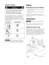
Stability Ratings
Warning
If you exceed the maximum slope, the traction unit
could tip, possibly crushing you or bystanders.
Do not drive the the traction unit on a slope
steeper than the maximum recommended slope.
To determine the degree of slope you can traverse with the
power rake installed on a traction unit, find the stability
rating for the hill position you want to travel in the table
below, then find the degree of slope for the same rating and
hill position in the Stability Data section of the traction unit
Operator’s Manual.
Orientation
Stability Rating
Front Uphill
B
Rear Uphill
D
Side Uphill
C
Important If you have a traction unit other than the
TX, use the counterweight on the traction unit when using
the power rake, or the traction unit may become unstable.
Setup
Extending the Caster Wheels
1. Extend the caster arms so that the caster wheels are in
the operating position.
2. Tighten the caster locking handles to secure the caster
arms in place.
Refer to your traction unit Operator’s Manual for
information on installing and removing attachments from
your traction unit.
Operation
Important Lift and move the attachment using the
traction unit.
Refer to your traction unit Operator’s Manual before
installing, operating, and removing the power rake.
Setting the Barrier Gap
The normal gap between the roller and barrier for average
conditions is about 1-1/4 inch. You can adjust this gap by
loosening the U-bolt that holds the barrier mount and
sliding it up or down. A wider opening allows more dirt
and rock to pass through. For finer raking, reduce the gap,
but be careful not to let the roller hit the barrier. The gap
should be the same all the way across (Fig. 2).
m-7592
1
2
3
Figure 2
1. Barrier
2. Roller
3. Barrier gap adjustment

6
Starting the Power Rake
With the end plates mounted in the working position and
the rake straight (the end plates parallel with the traction
unit track), material can be moved along, filling in the low
spots. This attachment is used to clear the ground of rocks,
so you do not need to clear all the rocks from the area prior
to operating the power rake.
1. Start the traction unit engine.
2. Lower the power rake slowly to the ground.
3. Engage the hydraulic control lever for auxiliary
implements.
4. Move the traction unit forward or backward as desired.
Note: For the roller to operate effectively, rotate it in
the opposite direction of the traction unit track. The
direction of the roller rotation is controlled by the
traction unit hydraulic controls. Refer to the chart
below.
Roller Rotation Travel Direction
Using the End Plates
The end plates contain the material in front of the roller
while the clean material passes between the roller and the
barrier. With the end plates mounted in the working
position and the rake straight (parallel with traction unit
track), the material can be moved, filling in the low spots.
You can mount the end plates to either the front or the back
of the power rake, depending on the raking direction. When
you move the end plates from front to back, you must move
the left one to the right side and the right one to the left
side.
To move the end plate, remove the hair pin from the end
plate pin, and pull out the pin from the end plate (Fig. 3).
m-7592
2
1
3
4
Figure 3
1. Hair pin
2. End plate pin
3. End plate
4. Angle locking pin
Angling the Roller
You can angle the roller 20° in either direction. For
windrowing, remove the angle locking pin (Fig. 3), slide
the angle mount to a new set of holes, and insert the pin.
Operating Tips
Important Do not drop the power rake onto the ground
with the roller turning. Sudden high speed jolts multiply the
stress to the drive line and can cause extreme damage.
• Always begin power raking at the slowest ground speed
possible. Increase the ground speed if conditions permit.
• Always use full throttle (maximum engine speed).
• If a rock or other obstruction gets into the teeth, stop the
hydraulics and drive the traction unit forward until the
obstruction is dislodged.
• Reduce the ground speed in rocky conditions. Increase
the ground speed if the conditions permit.
• The roller should be level with the ground. The power
rake should also be level with the ground front to back.
To accomplish this, raise or lower the gauge wheels and
use the traction unit’s tilt cylinder.
• To allow the roller to penetrate deeper into the ground,
loosen the handle and raise the gauge wheels. To raise
the roller, lower the gauge wheels.

7
• Because the chain case end of the roller is heavier than
the other end of the roller, set the tire closest to the
chain case down 3/4 inch lower than the opposite tire.
This will still give an even grade when landscaping.
• You can achieve further depth control by tilting the rake
forward on its gauge wheels to raise the roller, or tilt the
rake back to raise the gauge wheels and allow the roller
to penetrate more deeply.
• Check the air pressure in each tire regularly to maintain
an even and consistent grade.
• To break up compacted soil, roll back the attachment
plate to take the guide wheels off the ground so that
only the toothed roller is in contact with the ground.
Control the ground speed to avoid stalling the toothed
roller. Remove the end plates to allow material to move
out of the way if you are only trying to break up the
soil.
• To remove loose debris, tilt the traction unit attachment
plate until the guide wheels control the depth of the
toothed roller. You can angle the rake at this time for
windrowing debris or you can set the rake straight with
both end plates installed to collect debris. You can
increase the traction unit speed when you do this.
• For finish grading, tilt the rake forward until the teeth of
the toothed roller are barely touching the soil. You can
increase the traction unit speed to collect the material
from the high spots and leave it in the lower areas.
• To thatch grassy areas, tilt the traction unit attachment
plate forward to support the rake on the front gauge
wheels and the toothed roller raised so that the teeth are
just grazing the surface. The travel speed should be
slow.
Maintenance
Note: Determine the left and right sides of the machine from the normal operating position.
Recommended Maintenance Schedule
Maintenance Service
Interval
Maintenance Procedure
10 Hours • Check all hardware and tighten all nuts and bolts as needed.
Weekly
• Lubricate all pivot points.
• Lubricate the caster axle.
• Lightly lubricate the bearing at each end of the roller with 1 or 2 pumps of
grease.
• Check the tire pressure (Maintain at 20 psi cold).
Monthly
• Inspect the drive chain for stretching.
• Check the oil level in the chain case and add oil if necessary.
Quarterly • Change the oil in the chain case; add 1.5 pints of 85–140 wt. lube.
Storage • Paint chipped surfaces.
Caution
If you leave the key in the ignition switch, someone could start the engine, seriously injuring you
or bystanders.
Remove the key from the ignition switch before performing any maintenance.

8
Lubricating the Pivot Points
Lubricate the pivot points with general-purpose grease in
the locations shown in Figure 4.
m-7592
1
2
4
3
4
Figure 4
1. Caster axle (2)
2. Caster pivot point (2)
3. Pivot points
4. Roller bearing
Inspecting and Servicing the
Drive Chain
Inspect the drive chain monthly. A new chain has a
tendency to stretch, so check the chain tension to prevent it
from becoming excessively loose.
1. Loosen the bolt that holds the chain case cover.
2. If the chain appears excessively loose, replace the chain
or contact an Authorized Service Dealer.
Note: The chain tension is preset with the extension
spring.
3. Install the chain cover and bolt and torque the bolt to
75 ft-lb (102 N⋅m).
Changing the Oil in the Chain
Case
Change the chain oil every 200 operating hours.
Oil Type: 85W140
1. Park the power rake on a flat surface and ensure that the
chain case is perpendicular to the ground.
2. Lower the loader arms.
3. Shut off the engine and remove the key.
4. Remove the fill hole plug on top of the chain case
(Fig. 5).
1
2
3
4
Figure 5
1. Fill hole plug
2. Chain case
3. Oil drain cover
4. Level hole plug
5. Place a large drip pan under the drive chain case.
6. Remove the oil drain cover (Fig. 5).
7. When all the oil has drained from the oil drain cover,
install the cover.
8. Pour oil into the fill hole slowly until oil runs out the
level hole (Fig. 5).
9. Install the level hole plug and torque it to 100 in-lb
(1130 N⋅cm).
10. Install the fill hole plug (Fig. 5).
11. Wipe up any spilled oil.
12. Recycle oil according to local codes.

9
Storage
1. Before long term storage, wash the power rake with
mild detergent and water.
2. Check and tighten all bolts, nuts, and screws. Repair or
replace all damaged or worn parts.
3. Check the oil level in the chain case and add oil if
necessary.
4. Ensure that all hydraulic couplers are connected
together to prevent contamination of the hydraulic
system.
5. Paint all scratched or bare metal surfaces with paint
available from an Authorized Service Dealer.
6. Store the power rake in a clean, dry garage or storage
area. Cover it to protect it and keep it clean.
7. Store the power rake on a hard and level surface, and
block it to prevent it from moving.
Troubleshooting
Problem Possible Causes Corrective Action
The power rake does not operate.
1. The hydraulic coupler is not
completely connected.
1. Check and tighten all couplers.
2. The hydraulic coupler is
damaged.
2. Check the couplers and replace
any that are damaged.
3. There is an obstruction in a
hydraulic hose.
3. Find and remove the
obstruction.
4. The auxiliary valve on the
traction unit is not opening.
4. Repair the valve.
5. There is an obstruction in the
power rake.
5. Find and remove the
obstruction.
6. The drive chain is broken. 6. Repair or replace the chain.
7. The drive chain is loose. 7. Repair or replace the chain.
8. A hydraulic valve is damaged. 8. Repair or replace the hydraulic
valve.
9. The drive motor is damaged. 9. Repair or replace the drive
motor.
Oil is leaking from the traction unit.
1. A seal is worn or damaged. 1. Contact an Authorized Service
Dealer.
2. The hoses are loose or
damaged.
2. Contact an Authorized Service
Dealer.
3. The connections are loose or
damaged.
3. Contact an Authorized Service
Dealer.
4. The housing is worn or
damaged.
4. Contact an Authorized Service
Dealer.
5. The roller is out of position. 5. Contact an Authorized Service
Dealer.

10

11

/