Page is loading ...

Page 1
15000 WATT HOME GENERATOR SYSTEM
SERVICE & TROUBLESHOOTING MANUAL
MODELS 040213 & 040234
Part# 276351GS - June 2006

Page 2
FORWARD
This guide has been written and published by Briggs & Stratton Corporation to aid our dealers' mechanics and
company service personnel when servicing the products described herein.
It is assumed that these personnel are familiar with the servicing procedures for these products, or like or similar
products, manufactured by Briggs & Stratton Corporation. It is also assumed that they have been trained in the
recommended servicing procedures for these products, which includes the use of mechanics hand tools and any
special tools that might be required.
Proper service and repair is important to the safe, economical and reliable operation of all engine driven systems.
The troubleshooting, testing, service and repair procedures described in this guide are effective methods of
performing such operations.
We could not possibly know of and advise the service trade of all conceivable procedures or methods by which a
service might be performed, nor of any possible hazards and/or results of each procedure or method. We have not
undertaken any such wide evaluation. Therefore, anyone who uses a procedure or method not described by the
manufacturer must first satisfy himself that neither his safety, nor the safety of the product, will be endangered by the
service or operating procedure selected.
All information, illustrations, and specifications contained in this guide are based on the latest production information
available at the time of publication. However, Briggs & Stratton Corporation reserves the right to change, alter, or
otherwise improve the product at any time without prior notice.
Some components or assemblies of the product described in this guide may not be considered repairable.
Disassembly, repair and reassembly of such components may not be included in this guide.
Copyright © 2006 Briggs & Stratton Corporation
All rights reserved.

Page 3

Page 4

Service & Troubleshooting Guide - Home Generator System - Models 040213 & 040234 (15kW)
Table Of Contents
Page 5
1
15000 WATT HOME GENERATOR SYSTEM
SECTION 1 - GENERAL INFORMATION ... ............................................................................11
ACCESS TO THE GENERATOR .......................................................................................................11
To remove an access door: ........................................................................................................................... 11
To install an access door: .............................................................................................................................. 11
GENERATOR COMPONENTS ..........................................................................................................12
SYSTEM CONTROLS ........................................................................................................................13
GENERATOR CLEARANCES ...........................................................................................................14
ENGINE MAINTENANCE ...................................................................................................................14
Checking Oil Level ......................................................................................................................................... 14
Changing the Oil and Oil Filter ....................................................................................................................... 14
Replacing the Spark Plugs ............................................................................................................................ 15
Service Air Cleaner ........................................................................................................................................ 15
Valve Lash ..................................................................................................................................................... 15
Cooling Fins ................................................................................................................................................... 15
FUEL SUPPLY ...................................................................................................................................15
Reconfigure The Fuel System ....................................................................................................................... 16
GENERATOR AC CONNECTION SYSTEM ......................................................................................16
SYSTEM CONNECTIONS .................................................................................................................17
Wiring For The 2-Pin Connector: ................................................................................................................... 17
Wiring For The 10-Pin Connector: ................................................................................................................. 17
SETTING THE EXERCISE TIMER ....................................................................................................18
CONTROL MODULE ASSEMBLY (CMA) ..........................................................................................18
Power During CMA Fault Conditions ............................................................................................................. 18
Access To The CMA Board ........................................................................................................................... 19
CMA Connections .......................................................................................................................................... 19
FAULT CODE INDICATIONS .............................................................................................................20
Fault Code Index: .......................................................................................................................................... 20
Resetting The Fault Code Detection System ................................................................................................. 20
STOPPING THE SYSTEM FOR MAINTENANCE .............................................................................20

Service & Troubleshooting Guide - Home Generator System - Models 040213 & 040234 (15kW)
Table Of Contents
Page 6
1
SECTION 2 - TROUBLESHOOTING INFORMATION ............................................................23
(FC_1)
DEAD UNIT/LOW BATTERY VOLTAGE: ..........................................................................................23
Test 1
Check Battery: ................................................................................................................................................23
Test 2
Check DC Amperage at Battery: ....................................................................................................................23
Test 3
Check AC Voltage Input: ................................................................................................................................24
Test 4
Measure DC Output Voltage at the CMA .......................................................................................................24
(FC_2)
LOW OIL PRESSURE: .......................................................................................................................27
Test 1
Measure for Short-To-Ground ........................................................................................................................27
Test 2
Check Engine Oil Pressure ............................................................................................................................28
Test 3
Check Oil Pressure Switch .............................................................................................................................28
(FC_3)
LOW OUTPUT VOLTAGE: .................................................................................................................31
Test 1
Measure Circuit Breaker Load-Side Voltage: .................................................................................................31
Test 2
Measure Voltage at E1 and E2 ......................................................................................................................31
Test 3
Measure Circuit Breaker Line Voltage: ..........................................................................................................32
(FC_4)
ENGINE FAILS TO START: ...............................................................................................................35
Troubleshooting Engine Start Failures: ..........................................................................................................35
Test 1
Check Fuel Delivery System ..........................................................................................................................35
Test 2
Visually Inspect Generator .............................................................................................................................35
Test 3
Check Fuel Supply Pressure ..........................................................................................................................36
Test 4
Check Fuel Solenoid. .....................................................................................................................................36
Test 5
Check Fuel Regulator ....................................................................................................................................38

Service & Troubleshooting Guide - Home Generator System - Models 040213 & 040234 (15kW)
Table Of Contents
Page 7
1
Test 6
Check Ignition Spark: ..................................................................................................................................... 38
Test 7
Check Battery Components ........................................................................................................................... 38
Test 8
Check Starter Contactor Signal ..................................................................................................................... 39
Test 9
Check CMA Board Output ............................................................................................................................. 40
Test 10
Check Starter ................................................................................................................................................. 40
(FC_5)
UNDER FREQUENCY: ......................................................................................................................43
Test 1
Check No Load & Full Load Frequency: ........................................................................................................ 43
Test 2
Measure Frequency at E1 & E2 ..................................................................................................................... 44
(FC_6)
OVER FREQUENCY: .........................................................................................................................45
(FC_7)
HIGH OIL TEMPERATURE: ...............................................................................................................47
Test 1
Check Over Temperature Switch (OTS): ....................................................................................................... 47
Test 2
Check Wire #95 ............................................................................................................................................. 47
(FC_8)
TRANSFER SWITCH FAILURE: ........................................................................................................48
15kW WINDING TEST INDEX ...........................................................................................................49
CHECKING THE STATOR WINDING THROUGH THE HARNESS ..................................................50
CHECKING THE EXCITATION WINDING IN THE GENERATOR ....................................................50
CHECKING THE STATOR POWER WINDING .................................................................................51
CHECKING THE ROTOR WINDING .................................................................................................51

Service & Troubleshooting Guide - Home Generator System - Models 040213 & 040234 (15kW)
Table Of Contents
Page 8
1
SECTION 3 - UNIT DISASSEMBLY ........... ............................................................................53
REMOVING THE ACCESS DOORS ..................................................................................................53
REMOVE THE ROOF ASSEMBLY ....................................................................................................53
REMOVE THE EXHAUST BULKHEAD .............................................................................................53
REMOVE THE CONTROL PANEL BULKHEAD ................................................................................54
Remove Battery .............................................................................................................................................54
Remove Control Panel ...................................................................................................................................54
Disconnect Fuel Solenoid ..............................................................................................................................55
REMOVE THE MUFFLER ASSEMBLY .............................................................................................56
REMOVE COOLING DUCTS .............................................................................................................56
REMOVE THE STATOR ASSEMBLY ................................................................................................56
REMOVING THE ROTOR ASSEMBLY .............................................................................................59
INSPECTING THE ROTOR ASSEMBLY ...........................................................................................59
REMOVING THE ENGINE ADAPTOR ...............................................................................................60

Service & Troubleshooting Guide - Home Generator System - Models 040213 & 040234 (15kW)
Table Of Contents
Page 9
1
SECTION 4 - FINAL ADJUSTMENTS AND SPECIFICATIONS ..............................................61
OERATIONAL TESTS ........................................................................................................................61
Manual Operation Test (No Load) ................................................................................................................. 61
Automatic Operation Test (Load Transfer) .................................................................................................... 62
Generator Load Test (Full Rated Electrical Capacity And Fuel Consumption) .............................................. 62
SPECIFICATIONS ..............................................................................................................................64
WIRING DIAGRAM - MODEL 071013 - LOAD CONTROL CENTER ................................................65
SCHEMATIC - MODELS 040213 & 040234 - GENERATOR .............................................................66
WIRING DIAGRAM - MODELS 040213 & 040234 - GENERATOR ...................................................67
SCHEMATIC - MODELS 1813 & 1814 - TRANSFER SWITCH .........................................................68
WIRING DIAGRAM - MODELS 1813 & 1814 - TRANSFER SWITCH ...............................................69
SCHEMATIC - MODELS 071008 & 071009 - TRANSFER SWITCH .................................................70
WIRING DIAGRAM - MODELS 071008 & 071009 - TRANSFER SWITCH .......................................71
SCHEMATIC - MODELS 071010 & 071011 - TRANSFER SWITCH .................................................72
WIRING DIAGRAM - MODELS 071010 & 071011 - TRANSFER SWITCH .......................................73

Service & Troubleshooting Guide - Home Generator System - Models 040213 & 040234 (15kW)
Table Of Contents
Page 10
1

Service & Troubleshooting Guide - Home Generator System - Models 040213 and 040234 (15kW)
Section 1 - General Information
Page 11
1
SECTION 1 - GENERAL INFORMATION
ACCESS TO THE GENERATOR
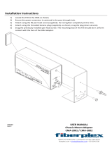
The 15kW Home Standby Generator System is equipped
with an enclosure that has three access doors (Fig.1).
The doors are named for the significant component(s)
located behind them. Starting with the side that has the
fuel connection and proceeding clockwise, the doors are
named:
• Oil Fill Door
• Control Panel Door
• Oil Drain Door
Each Home Standby Generator System is equipped with
two identical keys. These keys fit all the doors.
To remove an access door:
• Insert a key into the lock of the access door you
wish to remove and turn one quarter turn
counterclockwise.
• Open the latch with a quarter turn
counterclockwise.
• Open the door enough to clear its jambs and lift
the door from its hinges.
NOTE: When removing more than one door at a
time, it’s a good idea to mark the doors for proper
fit when reinstalling.
To install an access door:
• Mount the door hinge barrels on their respective
pins and close.
• Turn latch a quarter turn clockwise.
• Lock the door with the key.
Fig. 1 - Generator Access Doors
CAUTION: Do not operate the standby
generator for extended periods without all the
doors installed and closed. Failure to do so will
cause overheating.
Fuel Inlet Fitting
Lifting Holes
Oil Fill Door
Control Panel Door
Oil Drain Door

Service & Troubleshooting Guide - Home Generator System - Model 040234 (15kW)
Section 1 - General Information
Page 12
1
GENERATOR COMPONENTS
15 Amp Fuse - Protects the DC control circuits.
Air Cleaner- Protects engine by filtering dust and debris out of
intake air.
Battery - 12 Volt DC, AGM Type, 55 Amp-Hour sealed battery
provides power to start the engine. Battery receives trickle
charge whenever the generator is not running and when utility is
present.
Control Panel - Used for various tests, operation and
maintenance functions. (See “SYSTEM CONTROLS” on
page 13.)
Engine Label - Identifies engine model and type.
Exhaust Port - High performance muffler lowers engine noise
to comply with most residential codes.
Oil Dipstick - Used to check engine oil level.
Oil Drain Hose- Provided to facilitate changing oil.
Oil Fill Cap- Remove to service engine with recommended oil.
Oil Filter- Filters engine oil to prolong engine life.
Unit Data Decal - Identifies unit by model number, revision
and serial numbers.

Service & Troubleshooting Guide - Home Generator System - Models 040213 and 040234 (15kW)
Section 1 - General Information
Page 13
1
SYSTEM CONTROLS
15 Amp Fuse - Protects the Home Standby Generator
System DC control circuits. If the fuse has melted open or
was removed, the engine cannot crank or start. Replace
the fuse using only an identical ATO 15A fuse.
Circuit Breaker - Protects the system from over
current conditions and must be in the ON position to
supply power to the automatic transfer switch.
Digital Display - Used as an hour meter and to show
various fault indications. (See “FAULT CODE
INDICATIONS” on page 20.)
MANUAL OVER-RIDE- Used to start the engine
manually. Push and hold to start and shut unit down.
(SYSTEM switch must be in AUTO for MANUAL-
OVERIDE to operate.
Service Tool - For use by qualified service technicians
only.
SET EXERCISE - Used to set the exercise cycle start
time and day of the week. Exercise cycle only occurs in
the
AUTO mode.
SYSTEM - This two position switch operates as follows:
• AUTO position is the normal operating mode. If a
utility power outage is sensed, the generator will start
automatically. When utility power is restored, the
generator will shut down and is ready for the next
utility power outage.
• OFF position turn off a running generator, prevents
generator from starting and resets any fault
indications.

Service & Troubleshooting Guide - Home Generator System - Model 040234 (15kW)
Section 1 - General Information
Page 14
1
GENERATOR CLEARANCES
The generator enclosure should be a minimum of 5 ft.
(1.52 meter) from any combustible material. At least 5 ft.
(1.52 meter) of access room all around the enclosure
should be available. The unit exhaust grill should be at
least 10 ft. (3.05 meter) from any building opening
(window, door, vent etc.), and the exhaust gases should
not be able to accumulate in any occupied area (Fig. 2).
Fig. 2 - Generator System Clearances
ENGINE MAINTENANCE
NOTE: Detailed servicing information about this
Briggs & Stratton engine is available in the
“VANGUARD™ V-Twin OHV Repair Manual
(#272144).”
Checking Oil Level
Before placing the standby generator in service and at
the recommended maintenance interval, check the
engine oil level, as follows:
1. Remove Oil Fill door. Clean area around oil fill and
dipstick locations.
2. Remove dipstick. Wipe with clean cloth.
3. Insert dipstick fully. Remove and check oil level.
If oil level is low, remove oil fill cap and slowly add
recommended oil to bring level to
Full mark on dipstick
(Fig.3).
Fig. 3 - Oil Dipstick Markings
A reusable oil spout that fits most oil bottles is supplied to
make it easier to pour oil into the engine.
Changing the Oil and Oil Filter
Oil capacity is approximately 2-1/2 quarts (79 ounces or
2.3 liters) when changing oil and filter. Use only detergent
for service Grade SJ or greater synthetic oil. Change oil
after every 50 operating hours. Replace oil filter every 100
operating hours
.
If you are using this engine under dirty or dusty
conditions or in extremely hot weather, change the oil
more often. Use the following instructions to change the
oil while the engine is still warm:
1. Make sure the SYSTEM switch is set to
OFF.
2. Remove the 15 Amp fuse.
3. Un-clip and wipe the oil drain hose clean with a
rag. Place the oil drain hose into a suitable
container. Grasp the oil drain fitting and push it in
towards the engine. Rotate it counterclockwise to
its stop and pull the fitting outwards. Oil should
begin to flow out of the oil drain hose.
4. After the oil is drained, grasp the oil drain fitting
and rotate it clockwise until it locks in place.
Position the oil drain hose in its storage clip.
5. Place a suitable container beneath the oil filter and
remove the filter.

Service & Troubleshooting Guide - Home Generator System - Models 040213 and 040234 (15kW)
Section 1 - General Information
Page 15
1
6. Coat the o-ring of the new filter with fresh clean
engine oil. Turn the new filter clockwise by hand
until the gasket contacts the filter adapter, then
tighten 1/2 to 3/4 turn more.
7. Fill engine with oil until level is at the
FULL mark
on the dip stick.
8. Install and tighten the oil fill cap.
9. Run the engine for a minute, stop the engine and
check for oil leakage around the oil filter. Recheck
oil level.
Replacing the Spark Plugs
Replace the plugs every year. Use the recommended
spark plugs gapped for 0.020 in. (0.51 MM).
1. Stop the engine (See “STOPPING THE SYSTEM
FOR MAINTENANCE” on page 20.) and pull the
spark plug wires off of the spark plugs.
2. Clean around the spark plugs and remove them
from the cylinder head.
3. Clean off carbon deposits on the spark plug
electrode using a wire brush or commercial
solvent. Do not blast clean.
4. Set the plug gap as recommended. Install the
correctly gapped spark plugs into the cylinder
heads.
Torque to 15 lb. ft.
Service Air Cleaner
The engine air cleaner is one of the most important
areas to maintain. The engine will not run properly and
will be damaged if it is run with a dirty air cleaner system.
Use only genuine Briggs & Stratton parts. The use of
replacement parts which are not
UL® approved, may
damage the engine. Clean the foam pre-cleaner every
25 hours and the cartridge every 100 hours of operation.
Clean or replace more often in dusty or dirty conditions.
To service the air cleaner components:
1. Remove wing nut from top of air cleaner cover.
2. Remove winged from air filter retainer.
3. Service cartridge by tapping gently on a flat
surface. Do not oil cartridge. Replace if very dirty
or damaged.
4. Reinstall or replace air filter cartridge
5. Reinstall cover.
NOTE: Do not use petroleum solvents, e.g.
kerosene, which will cause the cartridge to
deteriorate. Do not use pressurized air to clean
cartridge. Pressurized air can damage the
cartridge.
Valve Lash
Valve lash must be checked while engine is cold after
every 100 hours of operation. Adjust if necessary (See
“VANGUARD™ V-Twin OHV Repair Manual (#272144).”
Valve lash is: Intake and Exhaust 0.004 - 0.006 in. (0.10
- 0.15 MM.)
Cooling Fins
Periodically, check to make sure the engine cooling fins,
screens and carburetor ducting are free of leaves, grass
or any other type of debris.
FUEL SUPPLY
The following fuel supplies are necessary to ensure
effective generator operation (Fig. 4)
.
Fig. 4 - Fuel Supply & Consumption Table
Models Natural Gas* LPG Vapor**
1/2 Load Full Load 1/2 Load Full Load
125 239 49.62+/- 5% 95.29+/- 5%040213-0 & 040234-0
* = Natural Gas in cubic feet per hour.
** = LPG Vapor in cubic feet per hour.
Fuel Pressures:
NG: 5-7” w.c.
LPG: 11-14” w.c.
These pressures at FULL LOAD with all gas
appliances turned ON.

Service & Troubleshooting Guide - Home Generator System - Model 040234 (15kW)
Section 1 - General Information
Page 16
1
NOTE: Air density is less at high altitudes,
resulting in less available engine power.
Specifically, engine power will decrease 3.5% for
each 1,000 feet (300 meters) above sea level
and 1% for each 10°F (5.6°C) above 77°F
(25°C). If the generator is not developing full
power, make sure these factors have been
considered when determining total generator
load output.
Reconfigure The Fuel System
The engine of your Home Standby Generator System is
factory calibrated to run on natural gas (NG). It may also
be operated on liquefied propane gas (LPG). There is no
additional hardware/equipment required to switch
between either fuel. However, LPG fuel inlet pressure
must be between 11 and 14 inches water column.
To reconfigure the fuel system for LPG use:
1. Open the control panel access door.
2. Set the SYSTEM switch to
OFF.
3. Set the generator main circuit breaker
OFF.
4. Remove the 15 Amp fuse.
5. Remove the cap from the fitting marked LPG
above the fuel regulator ( Fig. 5).
6. Remove the fuel supply hose from the NG fitting.
7. Pull hose through hole in sheet metal bulkhead
towards engine.
8. Remove and reverse fuel hose bushing and plug
in sheet metal bulkhead (Plug in top hole, bushing
in bottom hole).
9. Insert fuel hose in bottom hole towards regulator.
10. Install the hose on the LPG fitting.
11. Install the cap on the NG fitting ( Fig. 5).
Fig. 5 - Fuel System Fittings
12. Reinstall the 15 Amp fuse.
13. Set the generator main circuit breaker
ON.
14. Set the SYSTEM switch to
ON.
• Close the control panel access door.
The system is now ready to operate using LPG fuel.
The fuel mixer is set at the factory. No field adjustments
are required.
GENERATOR AC CONNECTION
SYSTEM
A single-phase, three-wire AC connection system is
used in the Home Generator System. The stator
assembly consists of a pair of stationary windings with
two leads brought out of each winding. The two windings
are connected together in series, resulting in a fixed
240VAC, 60Hz output. Stator output leads #11 and #44
are the two hot leads. The junction of leads #22 and #33
form the neutral lead (Fig. 6).
Fig. 6 - System (AC) Connections

Service & Troubleshooting Guide - Home Generator System - Models 040213 and 040234 (15kW)
Section 1 - General Information
Page 17
1
SYSTEM CONNECTIONS
Wiring For The 2-Pin Connector:
240 Volt Utility - Use to hook up the 240V utility leads
from the transfer switch to the generator.
Wiring For The 10-Pin Connector:
Fault Contacts - Use NO, COM and NC to hook up a
siren, light, etc. to alert you in case of a fault. Contacts
reverse state upon a fault condition.
Remote LED Output: - Use this to hook up the remote
LED supplied with the generator. The remote LED will
turn on and off in a series of blinks if certain faults are
detected in the generator.
Transfer Switch Communication - Use TxRx and TxRx
GND to transfer switch and optional wireless
StatStation
™ to monitor generator functions and for
FC_8 sensing.
+12 Volt DC, .5AMP Output - Internal power supply.
Fault Contacts
Transfer Switch
Communications
Remote LED Output
+12VDC,.5Amp Output
240VAC Utility
10 Pin Connector
2 Pin Connector

Service & Troubleshooting Guide - Home Generator System - Model 040234 (15kW)
Section 1 - General Information
Page 18
1
SETTING THE EXERCISE TIMER
The Home Standby Generator System is equipped with
an exercise timer that will start and exercise the system
once every seven days. During this exercise period, the
unit runs for approximately 20 minutes and then shuts
down. Electrical load transfer does not occur during the
exercise cycle (unless a utility power outage occurs).
A switch on the control panel is labeled
SET EXERCISE
(See “SYSTEM CONTROLS” on page 13.).
The
specific day and the specific time of day this switch is
pressed is retained by a memory chip on the Control
Module Assembly (CMA). The day and time is then
referenced by the chip to automatically initiate the
system exercise cycle in seven days.
To perform the set exercise procedure:
1. Make sure the SYSTEM switch is set to
AUTO.
2. Choose the day and time you want your Home
Standby Generator System to exercise.
3. Press and hold down the
SET EXERCISE switch for
three seconds. The LED on the control panel will
flash until “SET EXERCISE” is complete.
4. Release the
SET EXERCISE switch.
Set exercise is complete.
As an example, if you press the
SET EXERCISE switch on
Sunday morning at 10:00 AM, the unit will run an
exercise cycle the following Sunday at 10:00 AM (± 30
minutes).
NOTE: Set exercise will only work if the unit is
in the
AUTO mode and this exact procedure is
followed. The exerciser will need to be re-set if
the 12 VDC battery is disconnected or if you
remove the 15 AMP fuse.
If you want to change the day and time the unit
exercises, simply perform the set exercise procedure on
the exact day and time you want it to take place.
CONTROL MODULE ASSEMBLY (CMA)
The Control Module Assembly (CMA) is a printed circuit
board that is integrated with the control panel of the
Home Standby System. It contains all the logic circuits,
operator controls and system displays necessary to
operate, program and protect the generator. In addition,
it also has an access port for a diagnostic service tool to
aid in troubleshooting external system components and
internal control module failures. The CMA interprets and
monitors electrical inputs from all related circuits
throughout the standby installation.
Before replacing the CMA, all other circuits must be
tested to ensure proper operation. When a failure in the
CMA has been determined, it must be replaced as a
complete assembly.
Functions of the CMA:
• Battery Trickle Charge
• Set Exercise Timer (SET EXERCISE)
• Manual Start (MANUAL OVER-RIDE)
• Sensing Utility Voltage
• Automatic Start, in event of utility failure.
• Automatic Engine Cool-Down Timer
• Fault Detection with Automatic Shutdown
• Fault Indication Display (LED)
• Diagnostic access port (SERVICE TOOL)
• Hour Meter
Power During CMA Fault Conditions
When the Home Generator System is in an uncorrected
fault condition, the automatic transfer switch defaults to
UTILITY POWER. This ensures that utility power is
automatically applied to all circuits in the home
-regardless of an uncorrected generator fault.
If the unit fails to exercise at its prescribed time:
• Check the fault indication number displayed on
the generator control panel.
• Perform the SET EXERCISE procedure.

Service & Troubleshooting Guide - Home Generator System - Models 040213 and 040234 (15kW)
Section 1 - General Information
Page 19
1
Access To The CMA Board
The CMA is mounted behind the control panel door
behind the face of the control panel (Fig. 7).
1. Open and/or remove control panel door.
Fig. 7 - Location Of The Control Panel
2. Make sure the SYSTEM switch is set to OFF.
3. Remove the 15 AMP fuse.
4. Remove the circuit breaker cover.
5. Disconnect the 2-pin and 10-pin connectors.
6. Remove the four mounting screws that hold
the face of the control panel (Fig. 8).
Fig. 8 - Control Panel Mounting Hardware
CMA Connections
The CMA is connected to its various circuits through
three connectors that are mounted directly to the circuit
board. One connector has 8 pins , another has two
pins and the other has 10 pins (Fig. 9). All
receptacles have matching halves. The 2-pin plug
supplies 240VAC from UTILITY power. The 10-pin plug
is used for optional generator features. In addition, the
CMA also has connections for E1 and E2 which
sense 240VAC on the generator and four terminals
which can be used for optional battery and engine
warmers.
Fig. 9 - CMA Connector Receptacles And Pins
The 8-Pin Connector
The 8-pin connector is wired to the internal systems of
the unit and is the primary point of measurement for
troubleshooting the Home Standby System. When
directed to measure an electrical value, the location of a
meter probe is shown with an arrow in the picture and
the corresponding pin of the connector is
bold in a graphic illustration. The pin numbering of the
connector is shown with the CMA board exposed
(upsidedown in relation to the schematic) as in (Fig.10).
Fig. 10 - Measuring Electrical Values & Components
115-0005
1
2
3
4
5
6
7
8

Service & Troubleshooting Guide - Home Generator System - Model 040234 (15kW)
Section 1 - General Information
Page 20
1
A detailed illustration of the entire connector, as well as
the functions of each individual pin, is given in (Fig. 11).
Fig. 11 - The 8-Pin Connector And Its Functions
FAULT CODE INDICATIONS
The generator may have to run for long periods of time
with no operator present. For that reason, the CMA is
equipped with sensing circuits that automatically shut
down the generator in the event of potentially damaging
conditions.
A digital display is provided on the face of the control
panel to annunciate the type of failure (Fault Code) that
has occurred. In addition, there is an optional LED that
can be mounted elsewhere in the system to provide a
remote indication of generator failures.
When the CMA senses a condition that prevents the
generator from functioning properly, it shuts down the
generator and induces the digital display on the unit to
indicate
“FC_#” (# representing the number of the fault
code detected). Simultaneously, it signals the remote
LED to flash in a sequence of blinks that correspond to
the fault code indicated on the digital display.
Fault Code Index:
1. (FC_1) Low Battery Voltage
2.
(FC_2) Low Oil Pressure
3.
(FC_3) Low Output Voltage
4.
(FC_4) Engine Fails To Start
5.
(FC_5) Low Frequency
6.
(FC_6) Engine Over-speed
7.
(FC_7) High Oil Temperature
8.
(FC_8) Transfer Switch Failure
For example,
“FC_1” on the digital display would indicate
a low battery voltage condition and the remote LED
would flash once, pause, flash once again and continue
so on until reset or the condition is corrected.
Resetting The Fault Code Detection System
An operator or technician must reset the fault detection
system each time it activates.
To do so:
• Place the SYSTEM switch in the
OFF position for
5 seconds or more.
• Place the SYSTEM switch in the
AUTO position.
If the fault is not corrected, it will be detected again and
the unit will again go into Auto Shutdown with the same
fault code indication(s).
STOPPING THE SYSTEM FOR
MAINTENANCE
1. Ensure that the main line disconnect (MLD) is ON
and power is supplied to the UTILITY
CONNECTION lugs of the transfer switch.
2. Set the generator’s SYSTEM switch to
OFF.
3. Set the generator’s main circuit breaker to its
OFF
position.
Remove the 15 AMP fuse, as appropriate to your
maintenance needs.
1
2
3
4
5
6
7
8
Battery Trickle Charge (Wire #13)
Ground (Wire #0)
Start Circuit (Wire #56)
Fuel Solenoid (Wire #14)
Oil Temperature (Wire #95)
Oil Pressure (Wire #85)
Vacant
Vacant
Pin
Pin
Pin
Pin
Pin
Pin
Pin
Pin
/