Robe Robin ParFect 100 SW CE User manual
- Category
- Stroboscopes & disco lights
- Type
- User manual

1
Version 1.3 CE

2
Table of contents
1. Safety instructions ......................................................................................................... 3
2. Fixture exterior view ...................................................................................................... 5
3. Installation....................................................................................................................... 6
3.1 Connection to the mains ............................................................................................ 6
3.2 Installing the diusion lter ......................................................................................... 7
3.3 Installing barndoors and the gel frame ....................................................................... 8
3.4 Rigging the xture .................................................................................................... 10
3.5 DMX-512 connection ................................................................................................ 12
3.6. Wireless DMX operation ......................................................................................... 13
3.7. Stand-alone and Master/Slave operation ................................................................ 14
4. Control menu map ........................................................................................................ 15
5. Robin ParFect 100 SW - DMX chart ............................................................................ 17
5.1 LED zone order ........................................................................................................ 18
6. Control menu ............................................................................................................... 19
6.1 Addressing and master/slave setting (DMXA) .......................................................... 19
6.2 Fixture information (Info) .......................................................................................... 19
6.3 Personality (Pers) ..................................................................................................... 20
6.4 Manual Control (Manual) .......................................................................................... 20
6.5 Test program (Test Prg) ............................................................................................ 20
6.6 Stand-alone (St Alone) ............................................................................................. 20
6.7 Special functions (Special) ....................................................................................... 21
7. RDM ............................................................................................................................... 22
8. Error and information messages ................................................................................ 23
9. Technical Specications ..............................................................................................23
10. Maintenance and cleaning ......................................................................................... 26
11. Photometric diagrams ................................................................................................ 27
12. ChangeLog .................................................................................................................. 28
Robin ParFect 100 SmartWhite

3
FOR YOUR OWN SAFETY, PLEASE READ THIS USER MANUAL CAREFULLY
BEFORE POWERING OR INSTALLING YOUR ParFect 100 !
Save it for future reference.
This device has left our premises in absolutely perfect condition. In order to maintain this condition and to en-
sure a safe operation, it is absolutely necessary for the user to follow the safety instructions and warning notes
written in this manual.
The manufacturer will not accept liability for any resulting damages caused by the non-observance of this ma-
nual or any unauthorized modication to the device.
Please consider that damages caused by manual modications to the device are not subject to warranty.
The ParFect 100 was designed for indoor use and it is intended for
professional application only. It is not for household use.
1. Safety instructions
DANGEROUS VOLTAGE CONSTITUTING A RISK OF ELECTRIC SHOCK IS PRESENT WITHIN THIS UNIT!
Make sure that the available voltage is not higher than stated on the rear panel of the xture.
This xture should be operated only from the type of power source indicated on the marking label. If you are
not sure of the type of power supplied, consult your authorized distributor or local power company.
Always disconnect the xture from AC power before cleaning, removing or installing the fuses, or any part.
The power plug has to be accessible after installing the xture. Do not overload wall outlets and extension cords
as this canresult in re or electric shock.
Do not allow anything to rest on the power cord. Do not locate this xture where the cord may be damaged by
persons walking on it.
Make sure that the power cord is never crimped or damaged by sharp edges. Check the xture and the power
cord from time to time.
Refer servicing to qualied service personnel.
This xture falls under protection class I. Therefore this xture has to be connected to
a mains socket outlet with a protective earthing connection.
Do not connect this xture to a dimmer pack.
LED light emission. Risk of eye injury. Do not look into the beam at a distance of less
than 2 meters from the front surface of the product. Do not view the light output with
optical instruments or any device that may conncentrate the beam
If the xture has been exposed to drastic temperature uctuation (e.g. after transportation), do not switch it on
immediately. The arising condensation water might damage your device. Leave the device switched o until
it has reached room temperature.
Do not shake the xture. Avoid brute force when installing or operating the xture.
This xture was designed for indoor use only, do not expose this unit to rain or use near water.
When choosing the installation spot, please make sure that the xture is not exposed to extreme heat, moisture
or dust.

4
Air vents and slots in the xture´s head and base are provided for ventilation, to ensure reliable operation of
the device and to protect it from overheating.
Do not block the LEDs array with any object when the xture is under operation.
The openings should never be covered with cloth or other materials, and never must be blocked.
This xture should not be placed in a built-in installation unless proper ventilation is provided.
Only operate the xture after having checked that the housing is rmly closed and all screws are tightly fastened.
Always use a secondary safety cable when mounting this xture.
Make sure that the area below the installation place is blocked when rigging, derigging or servicing the xture.
Do not block the front objective LEDs with any object when the xture is under operation.
The xture becomes very hot during operation. Allow the xture to cool approximately 20 minutes prior to ma-
nipulate with it.
Operate the xture only after having familiarized with its functions. Do not permit operation by persons not
qualied for operating the xture. Most damages are the result of unprofessional operation!
Please use the original packaging if the xture is to be transported.
Please consider that unauthorized modications on the xture are forbidden due to safety reasons!
If this device will be operated in any way dierent to the one described in this manual, the product may suer
damages and the guarantee becomes void. Furthermore, any other operation may lead to dangers like short-
-circuit, burns, electric shock, crash etc.

5
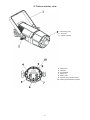
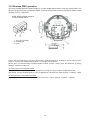
2. Fixture exterior view
4 - DMX OUT
5 - DMX IN
6 - Fuse holder
7 - Mains IN
8 - Mains OUT
9 - Display and control buttons
10 - Safety wire attachment point
1 - Mounting yoke
2 - Tilt locks
3 - Optical system

6
3. Installation
Fixtures must be installed by a Qualied electrician in accordance with all
national and local electrical and construction codes and regulation.
3.1 Connection to the mains
For protection from electric shock, the xture must be earthed!
The ParFect 100 is equipped with auto-switching power supply that automatically adjusts to any 50-60Hz AC
power source from 100-240 Volts.
Install a suitable plug on the power cord, note that the cores in the power cord are coloured according to the
following table. The earth has to be connected!
If you have any doubts about proper installation, consult a qualied electrician.
Core (EU) Core (US) Connection Plug Terminal Marking
Brown Black Live L
Light blue White Neutral N
Yellow/Green Green Earth
This device falls under class one and must be earthed (grounded)!
Design of the ParFect 100 allows to connect several xtures to AC mains power in one interconnected dai-
sy chain using power input and throughput connectors. Needed daisy chain cords are stated in the chapter
“Technical specications “
The max. number of connected xtures depends on the AC mains power voltage:
12 xtures at power supply= 230V
10 xtures at power supply= 208V
6 xtures at power supply= 120V
Do not overload the supply line and the connecting leads.
Wiring and connection work must be carried out by qualied sta!

7
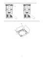
3.2 Installing the diusion lter
Disconnect the xture from mains before diusion lter installation
1.Disconnect the xture from mains.
2. Insert the screw (1) with the plastic washer (2) into diuser (3) and secure it by means of the
plastic washer (4.)
3. Insert the diuser (3) into the Parfect 100 and secure it by screwing the screw (1) into the thread hole (5) in
the plastic eggcrate. Keep the correct orientation of the diuser sections (6).

8
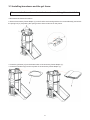
3.3 Installing barndoors and the gel frame
Disconnect the xture from mains before barndoors and the gel frame installation
1.Disconnect the xture from mains.
2. Screw the accessory frame adaptor (1) on the Parfect 100 housing with the four screws M4x8 (2) and unlock
the spring lock (3) via pushing this spring lock as show red arrows on the picture.
3. Insert the gel frame (4) into the bottom slots of the accessory frame adaptor (1).
4. Insert the barndoors (5) into the top slots of the accessory frame adaptor (1).

9
5. Secure both accessories by moving the spring lock (3) up as shows the red arrow on the picture.
Note: the barndoors can be rotated to desired position and secured in this position via the securing screw (6).

10
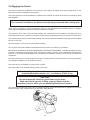
3.4 Rigging the xture
A structure intended for installation of the xture (s) must safely hold weight of the xture(s) placed on it. The
structure has to be certicated to the purpose.
The xture (xtures) must be installed in accordance with national and local electrical and construction codes
and regulation.
For overhead installation, the xture must be always secured with a safety wire
When rigging, derigging or servicing the xture staying in the area below the installation place, on bridges,
under high working places and other endangered areas is forbidden.
The operator has to make sure that safety-relating and machine-technical installations are approved by an
expert before taking into operation for the rst time and after changes before taking into operation another time.
The operator has to make sure that safety-relating and machine-technical installations are approved by a skilled
person once a year.
Allow the xture to cool for ten minutes before handling.
The projector should be installed outside areas where persons may walk by or be seated.
IMPORTANT! OVERHEAD RIGGING REQUIRES EXTENSIVE EXPERIENCE, including calculating working
load limits, installation material being used, and periodic safety inspection of all installation material and the
projector. If you lack these qualications, do not attempt the installation yourself, but use a help of professional
companies.
CAUTION: Fixtures may cause severe injuries when crashing down! If you have doubts concerning the safety
of a possible installation, do not install the xture!
The xture has to be installed out of the reach of public.
The xture must never be xed swinging freely in the room.
When installing the device, make sure there is no highly inammable
material (decoration articles, etc.) in a distance of min. 0.4 m.
CAUTION!
Use an appropriate clamp to rig the xture on the truss.
Make sure that the device is xed properly! Ensure that the
structure (truss) to which you are attaching the xtures is secure.
The xture can be placed by means of the unfolded mounting yoke on the stage oor or rigged on a truss (with
folded mounting yoke) without altering its operation characte ristics.
.

11
For overhead installation, install a safety wire that can hold at least 10 times the weight of the xture. Use only
safety wire with screw-on carabine. Fasten the safety cable in the attachment point and around the truss
as shown on the picture below.
When installing xtures side-by-side, avoid illuminating one xture with
another!
1-Clamp
2-Trust
3-Safety wire
4-Attachment point
5-Mounting yoke

12
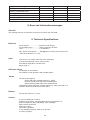
3.5 DMX-512 connection
The xture is equipped with 5-pin XLR sockets for DMX input and output. Only use a shielded twisted-pair
cable designed for RS-485 and 5-pin XLR-plugs and connectors in order to connect the controller with the
xture or one xture with another.
If you are using the standard DMX controllers, you can connect the DMX output of the controller directly with
the DMX input of the rst xture in the DMX-chain. If you wish to connect DMX-controllers with other XLR-out-
puts, you need to use adapter-cables.
Building a serial DMX-chain:
Connect the DMX-output of the rst xture in the DMX-chain with the DMX-input of the next xture. Always
connect one output with the input of the next xture until all xtures are connected. Up to 32 xtures can be
interconnected.
Caution: At the last xture, the DMX-cable has to be terminated with a terminator. Solder a 120 Ω resistor
between Signal (–) and Signal (+) into a 5-pin XLR-plug and plug it in the DMX-output of the last xture.
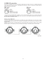
DMX output DMX input
XLR socket: XLRplug:
1 - Shield
2 - Signal (-)
3 - Signal (+)
4 - Used for wireless DMX
5 - Used for wireless DMX
1 - Shield
2 - Signal (-)
3 - Signal (+)
4 - Used for wireless DMX
5 - Used for wireless DMX

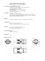
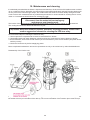
13
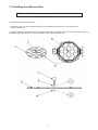
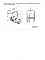
3.6. Wireless DMX operation
The external ROBE Wireless CRMX Dongle for compact ROBIN xtures allows receiving wireless DMX. This
device is equipped with the Lumen Radio CRMX module and antenna for receiving DMX signal. CRMX module
operates on the 2.4 GHz band.
Push in the 5-pin XLR plug (1) into 5-pin XLR sockit (4) and simultaneously locating pin (2) into hole (5) in the
xture. In this way the wireless DMX module is connected with the xture.
NOTE: when you disconnecting the DMX wireless module from the xture, press and hold lock (5) during
getting the wireless module out.
To link the xture with DMX transmitter.
The xture can be only linked with the transmitter by running the link procedure at DMX transmitter .
After linking , the level of DMX signal ( 0-100 %) is displayed in the menu item “Stat“ (Special -->Vireless -->Stat).
To unlink the xture from DMX transmitter.
The xture can be unlinked from receiver via the menu item “ Unlink“ (Special-->Vireless -->Unlink.).
1 - 5-pin XLR (female)
2 - Locating pin
3 - Lock
ROBE Wireless CRMX Dongle for
compact ROBIN xtures

14
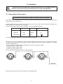
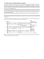
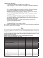
3.7. Stand-alone and Master/Slave operation
The xtures on a data link are not connected to the controller but can execute pre-set programs which can be
dierent for every xture. To set the program to be played, see the "Mast/Sla" menu (DMXA ---> Mast/Sla).
The Stand-alone operation can be applied to the single xture or to multiple xtures operating synchronously.
Synchronous operation of multiple xtures requires that they must be connected on a data link and one of them
is set as a master (master mode) and the rest as the slaves (slave mode). To set the xture as the master or
the slave, see the "Mast/Sla" menu.
The master xture starts simultaneous program start in the other slave xtures. All xtures have a denite,
synchronized starting point when playing back their programs. Every slave runs its program according to the
program number of the master. E.g. if the master runs program number 3, all slaves run their programs number 3.
Note: if the option "Play Master" is selected at the xture, this slave will play master´s program number 3, in-
stead of its own program 3.
Every xture runs its program repeatedly, starting the program step No.1 when requested by the master.
If the slave xture has a shorter program length, it will continuously repeat its program until the master xture
nishes its own program and restarts its program running (slave 1- prog. step 3 will not be nished) -see the
picture below.
If the slave xture has a longer program length, it will restart at prog. step 1 before it completes all its prog.
steps (slave 2 - prog. step 5 will not be played) - see the picture below.
Note: Disconnect the xtures from the DMX controller before master/slave operating, otherwise data collisions
can occur and xtures will not work properly!

15
4. Control menu map
Default settings=Bold print
Level 1 Level 2 Level 3 Level 4 Level 5 Level 6 Level 7
DMXA Set DMXA 001-255
Mode 1
:
Mode 5
Mast/Sla O
Master Play Prog 1
:
All
Slave Play Master
Play Slave
Info POn Time Total
Reset
DMX In
Powr 0-255
:
Dim F 0-255
Temp Current
Highest
High Res
Sw Ver IC-1
IC-2
Pers
DMX Pres Mode 1
:
Mode 5
Display Turn
On/O T On, O
Contrast 0-100%
Backlight 0-100%
Audio On, O
Mic Sens 0...10...19
Fans Auto, High, Silen
Temp Uni °C, °F
I Ef Pos Pan
:
Dimm F
Store
Defaults
Manual Pres E R L 1 Pos 1-Pos 5
:
Dimm Pos 1- Pos 5
Manual C Powr 0-255
:
Dim F 0-255
Test Prg
Sta Alone Music T On, O
Auti Run O

16
Level 1 Level 2 Level 3 Level 4 Level 5 Level 6 Level 7
Prog 1
:
All
Pr Play Prog 1
:
All
Pr Edit Prog 1 Step 1 Powr
Prog 2 : :
Prog 3 Step 40 F.Tim 0-25.5
S.Tim 0-25.5
COPY
Prg En 1-40
Special RDM Low
RDM Hight
Wireless Stat
Unlink
Sw Upd On, O

17
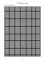
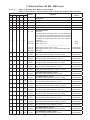
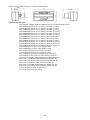
5. Robin ParFect 100 SW - DMX chart
Version 1.1 Mode 1- Standard 16bit, Mode 2 - Reduced 8bit,
Mode 3- Basic, Mode 4 - Extended 16bit, Mode 5 - Robin 100 LedBeam SW compatible
Mode/Channel
Value Function
Type of
control
1 2 3 4 5
- - - - 1
No function
- - - - 2
No function
- - - - 3
No function
- - - - 4
No function
- - - - 5
No function
1 1 1 1 6
0 - 119
120-124
125-129
130-145
146-161
162-255
Special functions
Reserved
To activate Audio Control function , stop in DMX value
for at least 3sec. and shutter must be closed at least
3sec. (Shutter channel 7/5/3/15/20 must be at range of
0-31DMX). Corresponding menu items are temporily
overrided.
Audio control On
Audio control O
--------------------------------------------------------------------
Eect speed control, slow--> fast
Eect speed control, fast--> slow /opposite direction/
Reserved
step
step
proportional
proportional
2 2 - - -
0-255
Warm White (8 bit) - all zones
Warm white LEDs saturation control (0-100%) proportional
3 - - - -
0-255
Warm white ne (16 bit) - all zones
Fine warm white LEDs saturation control proportional
4 3 - - -
0-255
Cool white (8 bit) - all zones
Cool white LEDs saturation control (0-100%) proportional
5 - - - -
0-255
Cool white ne (16 bit) - all zones
Fine cool white LEDs saturation control proportional
- - - 2 7
0-255
Warm White (8 bit) - zone 1
Warm white LEDs saturation control (0-100%) proportional
- - - 3 8
0-255
Warm white ne (16 bit) - zone 1
Fine warm white LEDs saturation control proportional
- - - 4 9
0-255
Cool white (8 bit) - zone 1
Cool white LEDs saturation control (0-100%) proportional
- - - 5 10
0-255
Cool white ne (16 bit) - zone 1
Fine cool white LEDs saturation control proportional
- - - 6 11
0-255
Warm White (8 bit) - zone 2
Warm white LEDs saturation control (0-100%) proportional
- - - 7 12
0-255
Warm white ne (16 bit) - zone 2
Fine warm white LEDs saturation control proportional
- - - 8 13
0-255
Cool white (8 bit) - zone 2
Cool white LEDs saturation control (0-100%) proportional
- - - 9 14
0-255
Cool white ne (16 bit) - zone 2
Fine cool white LEDs saturation control proportional
- - - 10 15
0-255
Warm White (8 bit) - zone 3
Warm white LEDs saturation control (0-100%) proportional
- - - 11 16
0-255
Warm white ne (16 bit) - zone 3
Fine warm white LEDs saturation control proportional
- - - 12 17
0-255
Cool white (8 bit) - zone 3
Cool white LEDs saturation control (0-100%) proportional
- - - 13 18
0-255
Cool white ne (16 bit) - zone 3
Fine cool white LEDs saturation control proportional

18
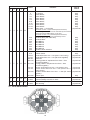
Mode/Channel
Value Function
Type of
control
1 2 3 4 5
6 4 2 14 19
0
1-2
3-4
5-6
7-8
9-10
11-12
13-14
15-16
17-247
248
249
250
251
252
253
254
255
Virtual colour wheel & zone eects
No function
White 2800 K
White 3200 K
White 3800 K
White 4200 K
White 4600 K
White 5000 K
White 5600 K
White 6300 K
Warm white --> Cool white
Item Audio control = O (channel Special Functions).
The following zone eects can be controlled by the channel
Special Functions (DMX values of 130-161)
Item Audio control = On (channel Special Functions).
The following zone eects are controlled by sound
Rainbow eect (with fade time)
Rainbow eect
Zone eect 1
Zone eect 2
Zone eect 3
Zone eect 4
Zone eect 5
Random colour selection
step
step
step
step
step
step
step
step
step
proportional
step
step
step
step
step
step
step
step
7 5 3 15 20
0-31
32-63
64-95
96-127
128-143
144-159
160-175
176-191
192-223
224-255
Shutter/Strobe
Shutter closed
Strobe eect from slow--> fast (zone 2 and 3 only)
Strobe eect from slow--> fast (All zones together)
Reserved
Opening pulses in sequences from slow--> fast
(All zones together)
Closing pulses in sequences from fast--> slow
(All zones together)
Random strobe eect from slow--> fast (random zone)
Random strobe eect from slow--> fast (random zone +
random strobe)
Random strobe eect from slow --> fast (All zones
together)
Shutter open
step
proportional
proportional
proportional
proportional
proportional
proportional
proportional
step
8 6 4 16 21
0-255
Dimmer (8 bit)
Dimmer intensity from 0% to 100% proportional
9 - - 17 22
0-255
Dimmer ne (16 bit)
Fine dimming proportional
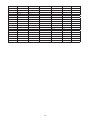
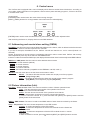
5.1 LED zone order

19
6. Control menu
The ParFect 100 is equipped with 2-row LCD display which allows to set the xture´s behaviour according to
your needs, obtain information on its operation, test its various parts and lastly program it, if it has to be used
in a stand-alone mode.
Control panel:
[ESCAPE] button used to leave the menu without saving changes.
[NEXT] , [PREV] buttons for moving between menu items and for value adjusting.
[ENTER] button used to enter the selected menu (menu item) and to conrm adjusted value.
After switching the xture on, display shows current DMX address.
6.1 Addressing and master/slave setting (DMXA)
Set DMXA- Use this menu item to set the DMX start address of the xture, which is dened as the rst channel
from which the ParFect 100 will respond to the controller.
If you set, for example, the address 18, the ParFect 100 will use channels 18 - 34 for control (if Mode 1 is
selected).
Please, be sure that you do not have any overlapping channels in order to control each ParFect 100 correctly
and independently from any other xture on the DMX data link.
If there is no data received at the DMX input, the display will start to ash "0001” with actually stored DMX address.
DMX Pres - DMX preset. Use the menu to select desired channel mode.
Mode 1 - 9 control channels (default)
Mode 2 - 6 control channels
Mode 3 - 4 control channels
Mode 4 - 17 control channels
Mode 5 - 22 control channels (compatible to the LEDBeam 100 SW, mode 1)
Mast/Sla- Use this menu item to set the xture as a master or slave.
Master -
The xture will behave as the master and can play one of ten programs
(Prog 1-Prog 9, All)
Slave -
The xture will behave as the slave and can play either master´s program
(Play Master) or its respective program (Play Slave).
6.2 Fixture information (Info)
Pon Time - Power on time. Select this menu to read the number of xture operation hours.
Total -
The item shows the total number of the operation hours since
the ParFect 100
has been fabricated.
Reset -
The item shows the number of the operation hours that the
ParFect 100
has been powered on since the counter was last reset.
In order to reset this counter to 0, press and hold both [NEXT] and [PREV] buttons and the
[Enter] button at the same time.
DMX In - DMX readout. The menu is used to read DMX values of each channel received by the xture.
Temp - Temperature. The menu shows temperature in the LED module.
Current - A current temperature of the LED module.
Highest - A maximum temperature of the the LED module since the xture has
been fabricated.
High Res - A maximum temperature of the the LED module since the counter
was last reset.
In order to reset this counter, press and hold both [NEXT] and [PREV] buttons and the

20
[Enter] button at the same time.
Sw Ver - Software versions. Select this item to read the software version of the xture modules.
IC-1 - A display processor.
IC-2 - LED control processor.
6.3 Personality (Pers)
DMX Pres - DMX preset. Use the menu to select desired channel mode.
Mode 1 - 9 control channels (default)
Mode 2 - 6 control channels
Mode 3 - 4 control channels
Mode 4 - 17 control channels
Mode 5 - 22 control channels (compatible to the LEDBeam 100 SW, mode 1)
Display - Display adjusting. This menu allows you to adjust the display behaviour.
Turn - This function turns the display by 180°.
On/O T - This function allows you to keep the display permanent on or turn it o two
minutes after last pressing any button on the control panel.
Contrast- Use this function to adjust contrast of the display (0-100%).
Backlight- Use this function to adjust backlight of the display (0-100%).
Audio - Audio mode. If this mode is on, the eects on the Virtual Colour Wheel are controlled via sound and
do not respond to the speed control on the channel Special Functions.
Mic Sens - Microfon sensitivity. Enter the menu if you want to adjust the microphone sensitivity ( 1-max.,
19-min.).
Fans - Fan mode. Use the menu to set the xture fan to the max. fan power mode ("High"), to the auto- control
mode ("Auto") or to the silent mode ("Silen").
Temp Uni - Temperature unit. Use the menu item to change temperature unit from °C to °F.
I Ef Pos - Init eect positions. Use the menu to set all eects to the desired positions at which they will stay
after switching the xture on without DMX signal connected.
Defaults - The menu item allows to set all xture parameters to the default (factory) values.
6.4 Manual Control (Manual)
Pres E - Preset eects. Use the menu to show preset positions of each channel eect.
Manual C - Manual control. Use the menu to control all xture channels by means of the control panel.
6.5 Test program (Test Prg)
Use this menu to to run a special demo-test sequences without an external controller, which will show you some
possibilities of using the ParFect 100.
6.6 Stand-alone (St Alone)
The ParFect 100 oers three built-in programs (Prog 4-Prog 6 and "All") and three user-editable programs
(Prog 1-Prog 3), each up to 40 steps. The item "All" icludes programs 4-6 in a chain.
Music T - Music trigger. Select this function to enable the sound control of the running program via the built-in
microphone (the option Audio in the Personality menu has to be set on).
Auto Run - Presetting playback. This function allows you to select the program which will be played in the
stand-alone mode after switching the xture on. Selected program will be played continuously in a loop.
O - The option disables „Auto Run” function.
Page is loading ...
Page is loading ...
Page is loading ...
Page is loading ...
Page is loading ...
Page is loading ...
Page is loading ...
Page is loading ...
-
 1
1
-
 2
2
-
 3
3
-
 4
4
-
 5
5
-
 6
6
-
 7
7
-
 8
8
-
 9
9
-
 10
10
-
 11
11
-
 12
12
-
 13
13
-
 14
14
-
 15
15
-
 16
16
-
 17
17
-
 18
18
-
 19
19
-
 20
20
-
 21
21
-
 22
22
-
 23
23
-
 24
24
-
 25
25
-
 26
26
-
 27
27
-
 28
28


Robe Robin ParFect 100 SW CE User manual
- Category
- Stroboscopes & disco lights
- Type
- User manual
Ask a question and I''ll find the answer in the document
Finding information in a document is now easier with AI
Related papers
-
Robe Robin ParFect S1 User manual
-
-
-
-
-
-
-
-
-
Other documents
-
Anolis ArcPar™ 100 User manual
-
-
-
-
Elation DarkFX UV Wash 2000 User manual
-
-
-
-
-
AVE STAGEPAR QUAD18 User manual