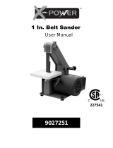
Powermatic 31A User guide

Type
User guide

This manual is also suitable for

Operating Instructions and Parts Manual
Combination Belt/Disc Sander
Model 31A
Powermatic
427 New Sanford Road
LaVergne, Tennessee 37086 Part No. M-0460267
Ph.: 800-274-6848 Revision H2 10/2018
www.powermatic.com Copyright © 2014 Powermatic
This .pdf document is bookmarked
2
Warranty and Service
Powermatic
®
warrants every product it sells against manufacturers’ defects. If one of our tools needs service or
repair, please contact Technical Service by calling 1-800-274-6846, 8AM to 5PM CST, Monday through Friday.
Warranty Period
The general warranty lasts for the time period specified in the literature included with your product or on the official
Powermatic branded website.
Powermatic products carry a limited warranty which varies in duration based upon the product. (See chart
below)
Accessories carry a limited warranty of one year from the date of receipt.
Consumable items are defined as expendable parts or accessories expected to become inoperable within a
reasonable amount of use and are covered by a 90 day limited warranty against manufacturer’s defects.
Who is Covered
This warranty covers only the initial purchaser of the product from the date of delivery.
What is Covered
This warranty covers any defects in workmanship or materials subject to the limitations stated below. This warranty
does not cover failures due directly or indirectly to misuse, abuse, negligence or accidents, normal wear-and-tear,
improper repair, alterations or lack of maintenance. Powermatic woodworking machinery is designed to be used with
Wood. Use of these machines in the processing of metal, plastics, or other materials outside recommended
guidelines may void the warranty. The exceptions are acrylics and other natural items that are made specifically for
wood turning.
Warranty Limitations
Woodworking products with a Five Year Warranty that are used for commercial or industrial purposes default to a
Two Year Warranty. Please contact Technical Service at 1-800-274-6846 for further clarification.
How to Get Technical Support
Please contact Technical Service by calling 1-800-274-6846. Please note that you will be asked to provide proof
of initial purchase when calling. If a product requires further inspection, the Technical Service representative will
explain and assist with any additional action needed. Powermatic has Authorized Service Centers located throughout
the United States. For the name of an Authorized Service Center in your area call 1-800-274-6846 or use the Service
Center Locator on the Powermatic website.
More Information
Powermatic is constantly adding new products. For complete, up-to-date product information, check with your local
distributor or visit the Powermatic website.
How State Law Applies
This warranty gives you specific legal rights, subject to applicable state law.
Limitations on This Warranty
POWERMATIC LIMITS ALL IMPLIED WARRANTIES TO THE PERIOD OF THE LIMITED WARRANTY FOR EACH
PRODUCT. EXCEPT AS STATED HEREIN, ANY IMPLIED WARRANTIES OF MERCHANTABILITY AND FITNESS
FOR A PARTICULAR PURPOSE ARE EXCLUDED. SOME STATES DO NOT ALLOW LIMITATIONS ON HOW
LONG AN IMPLIED WARRANTY LASTS, SO THE ABOVE LIMITATION MAY NOT APPLY TO YOU.
POWERMATIC SHALL IN NO EVENT BE LIABLE FOR DEATH, INJURIES TO PERSONS OR PROPERTY, OR
FOR INCIDENTAL, CONTINGENT, SPECIAL, OR CONSEQUENTIAL DAMAGES ARISING FROM THE USE OF
OUR PRODUCTS. SOME STATES DO NOT ALLOW THE EXCLUSION OR LIMITATION OF INCIDENTAL OR
CONSEQUENTIAL DAMAGES, SO THE ABOVE LIMITATION OR EXCLUSION MAY NOT APPLY TO YOU.
Powermatic sells through distributors only. The specifications listed in Powermatic printed materials and on the official
Powermatic website are given as general information and are not binding. Powermatic reserves the right to effect at
any time, without prior notice, those alterations to parts, fittings, and accessory equipment which they may deem
necessary for any reason whatsoever.
Product Listing with Warranty Period
90 Days – Parts; Consumable items
1 Year – Motors, Machine Accessories
2 Year – Woodworking Machinery used for industrial or commercial purposes
5 Year – Woodworking Machinery
NOTE: Powermatic is a division of JPW Industries, Inc. References in this document to Powermatic also apply to
JPW Industries, Inc., or any of its successors in interest to the Powermatic brand.
3
Table of Contents
Warranty and Service .................................................................................................................................... 2
Table of Contents .......................................................................................................................................... 3
IMPORTANT SAFETY INSTRUCTIONS ...................................................................................................... 4
Warning ......................................................................................................................................................... 4
Introduction.................................................................................................................................................... 6
Specifications ................................................................................................................................................ 6
Grounding Instructions .................................................................................................................................. 7
Dimensions.................................................................................................................................................... 8
On-Off Switch Padlock .................................................................................................................................. 8
Unpacking ..................................................................................................................................................... 9
Contents of the Shipping Container .......................................................................................................... 9
Assem bly ..................................................................................................................................................... 10
Installing Sander on Stand ...................................................................................................................... 10
Installing and Tracking Abrasive Belt ...................................................................................................... 11
Installing Fence ....................................................................................................................................... 11
Installing Abrasive Disc ........................................................................................................................... 12
Installing Table ........................................................................................................................................ 12
Dust Outlet and Cord Plate ..................................................................................................................... 13
Switch (Single Phase Model) .................................................................................................................. 13
Electrical Connections ................................................................................................................................. 13
Adjustments ................................................................................................................................................ 15
Platen Adjustment ................................................................................................................................... 15
Sanding Table Adjustment ...................................................................................................................... 15
Work Stop ................................................................................................................................................ 16
Belt Arm Positioning ................................................................................................................................ 16
Operation..................................................................................................................................................... 17
Template Forms ...................................................................................................................................... 17
Fence/Table ............................................................................................................................................. 17
Types of Operations ................................................................................................................................ 18
User-Maintenance ....................................................................................................................................... 19
Lubrication ............................................................................................................................................... 19
Replacing Drive Belt ................................................................................................................................ 19
Extension Cords ...................................................................................................................................... 14
Guide to Sanding Belts and Discs .............................................................................................................. 20
Troubleshooting 31A Belt/Disc Sander ....................................................................................................... 21
Replacement Parts ...................................................................................................................................... 21
Parts List: 31A Stand Assembly (1PH) .................................................................................................... 22
31A Stand Assembly (1PH) ..................................................................................................................... 23
Parts List: 31A Stand Assembly (3PH) .................................................................................................... 24
31A Stand Assembly (3PH) ..................................................................................................................... 25
Parts List: 31A Sander Body Assembly ................................................................................................... 26
31A Sander Body Assembly .................................................................................................................... 28
Electrical Connections (1 Phase) ................................................................................................................ 29
Electrical Connections (3 Phase) ................................................................................................................ 30
4
IMPORTANT SAFETY
INSTRUCTIONS
Warning
As with all machines, there is a certain amount
of hazard involved with the use of this sander.
Use the machine with the respect and caution
demanded where safety precautions are
concerned. When normal safety precautions are
overlooked or ignored, personal injury to the
operator can result.
Read, understand and follow the safety and
operating instructions found in this manual.
Know the limitations and hazards associated
with this machine.
Electrical grounding. Make certain that the
machine frame is electrically grounded and that
a ground lead is included in the incoming
electrical service. In cases where a cord and
plug are used, make certain that the grounding
plug connects to a suitable ground. Follow the
grounding procedure indicated in the National
Electrical Code.
Eye safety. Wear an approved safety shield,
goggles, or glasses to protect eyes. (NOTE:
Common eyeglasses are only impact-resistant,
they are not safety glasses.)
Personal protection. Before operating the
machine, remove tie, rings, watch and other
jewelry and roll up sleeves above the elbows.
Remove all loose outer clothing and confine long
hair. Protective type footwear should be used.
Where the noise exceeds the level of exposure
allowed in Section 1910.95 of the OSHA
Regulations, use hearing protective devices. Do
not wear gloves.
Guards. Keep the machine guards in place at
all times when the machine is in use. If removed
for maintenance purposes, use extreme caution
and replace guards on completion of the
maintenance task before operating the sander.
DO NOT operate the machine with the guards
off except for the belt end guard which swings
away to allow for contour sanding. Keep that
guard in place except when contour sanding and
swing it back into position immediately after
completing the contour sanding task.
Work area. Keep the floor around the machine
clean and free of scrap material, saw dust, oil
and other liquids to minimize the danger of
tripping or slipping. Make certain the work area
is well lighted and that a proper exhaust system
is used to minimize dust. Powermatic
recommends the use of anti-skid floor strips on
the floor area where the operator normally
stands and that each machine’s work area be
marked off. Provide adequate work space
around the machine.
Don’t use in dangerous environment. Do not
expose sander to rain or use in damp locations.
Keep children away. All visitors should be kept
a safe distance from work area.
Make workshop child proof with padlocks,
master switches, or by removing starter keys.
Avoid accidental starting: Make certain motor
switch is in off position before connecting power
to the machine.
Operator position. Maintain a balanced stance
and keep your body under control at all times.
Do not over-reach. Do not stand in line with the
belt in the direction that it is moving when the
work stop is not in use.
Belt and Disc Direction. Avoid kickback by
sanding in accordance with the directional
arrows. Proper belt direction is from the idler
pulley towards the drive pulley. Proper disc
rotation is counterclockwise facing the disc.
CAUTION: Sand on the section of the disc from
the center to the left edge. DO NOT use the
right hand portion for sanding.
Housekeeping. Before turning on machine,
remove all extra equipment such as keys,
wrenches, scrap, and cleaning rags away from
the machine.
Careless acts. Give the work you are doing
your undivided attention. Looking around,
carrying on a conversation, and “horseplay” are
careless acts that can result in serious injury.
Disconnect machine before performing any
service or maintenance.
Hand safety. Keep fingers and hands away
from the belt or disc. DO NOT clear sawdust
from the table with the hands; use a brush. On
small or thin parts, use a push stick or jig to
keep the hands from contacting the abrasive. If
using the fence, avoid getting fingers too close
to the fence to prevent pinching. Never wear
gloves while operating the sander.
5
Machine capacity. Do not try to force the
sander to remove material faster than the power
available from the drive motor. The use of light
pressure on either disc or belt sanding and
moving the part back and forth will maximize belt
or disc life, help to minimize the chances of an
accident and keep the force within the capacity
of the drive motor.
Machine adjustments. Make all machine
adjustments with power off except belt tracking.
Belt tracking should be checked manually before
starting the sander, but final adjustment may
have to be made after starting up the sander.
Table safety. Be sure the table is locked in
position before placing stock on it and that its
front edge is within 1/16” or less, of the disc or
belt.
Job completion. If the operator leaves the
machine area for any reason, the sander should
be turned "off" and the abrasive belt and disc
should come to a complete stop before his/her
departure. In addition, if the operation is
complete, he should clean the sander and the
work area. Never clean the sander with power
"on" and never use the hands to clear sawdust
and debris; use a brush.
Replacement parts. Use only Powermatic or
factory authorized replacement parts and
accessories; otherwise the warranty and
guarantee is null and void.
Misuse. Do not use this Powermatic sander for
other than its intended use. If used for other
purposes, Powermatic disclaims any real or
implied warranty and holds itself harmless for
any injury or damage which may result from that
use.
If you are not thoroughly familiar with the
operation of sanders, obtain advice from your
supervisor, instructor or other qualified person.
Drugs, alcohol, medication. Do not operate
this machine while under the influence of drugs,
alcohol, or any medication.
Prevent unauthorized use: When the machine
is not in use, lock out the switch to prevent
accidental or unauthorized starting. To do this,
either remove the switch key and store in a
place inaccessible to children and others not
qualified to use the machine; or purchase and
insert a padlock through the hole in the start
switch.
Familiarize yourself with the following safety notices used in this manual:
This means that if precautions are not heeded, it may result in minor injury and/or
possible machine damage.
This means that if precautions are not heeded, it may result in serious or possibly even
fatal injury.
- - SAVE THESE INSTRUCTIONS - -
WARNING: Drilling, sawing, sanding or
machining wood products generates wood
dust and other substances known to the
State of California to cause cancer. Avoid
inhaling dust generated from wood products
or use a dust mask or other safeguards for
personal protection.
Wood products emit chemicals known to the
State of California to cause birth defects or
other reproductive harm. For more
information go to http://www.p65warnings.ca.
gov/wood.
WARNING: This product can expose you
to chemicals including lead which is known
to the State of California to cause cancer
and birth defects or other reproductive harm.
For more information go to http://www.
p65warnings.ca.gov.
6
Introduction
This manual is provided by Powermatic covering the safe operation and maintenance procedures for a
Powermatic Model 31A Combination Belt/Disc Sander. This manual contains instructions on installation,
safety precautions, general operating procedures, maintenance instructions and parts breakdown. This
machine has been designed and constructed to provide consistent, long-term operation if used in
accordance with instructions set forth in this manual. If there are any questions or comments, please
contact either your local supplier or Powermatic. Powermatic can also be reached at our web site:
www.powermatic.com.
Register your product using the mail-in card provided, or register online:
http://www.powermatic.com/us/en/service-and-support/product-registration/
Specifications
Model Number ................................................................................ 31A .................................................... 31A
Stock Number (1 Phase model) ........................................... 1791291K ..........................................................
Stock Number (3 Phase model) ........................................................... .......................................... 1791292K
Abrasive Belt Size (in.) ................................................................ 6 x 48 ................................................ 6 x 48
Disc Size (in.) ................................................................................... 12 ...................................................... 12
Table Working Height (in.) ........................................... 34 disc, 36 belt .................................. 34 disc, 36 belt
Sanding Arm Locking Positions (deg.) ............................. 0, 45 and 90 ...................................... 0, 45 and 90
Disc Table Size (in.) ............................................................. 17-1/4 x 9 .......................................... 17-1/4 x 9
Disc Table Tilt (deg.) .................................................... 15 up, 45 down ................................. 15 up, 45 down
Belt Table Size (in.) ........................................................ 13-1/4 x 7-1/2 .................................... 13-1/4 x 7-1/2
Belt Table Tilt (deg.) ................................................................ 45 down ............................................ 45 down
Disc Speed (RPM) ....................................................................... 2375 .................................................. 2375
Belt Speed (SFPM) ...................................................................... 2410 .................................................. 2410
Dust Port Diameter (in.) ..................................................................... 4 ........................................................ 4
Dust Collection Minimum CFM Required ....................................... 400 .................................................... 400
Motor ............................................................. 1-1/2HP, 1PH, 115/230V ...................... 2HP, 3PH, 230/460V
1
(pre-wired 115V), 60Hz, 14/7A (pre-wired 230V), 60 Hz, 7/3.5A
Recommended circuit
2
............................................................... 30/20 ................................................. 20/10
Overall Dimensions (LxWxH)(in.) ......................... 24 x 31-1/4 x 54-1/2 .......................... 24 x 31-1/4 x 54-1/2
Net Weight (lbs.) ............................................................................ 247 .................................................... 247
Shipping Weight (lbs.) .................................................................... 275 .................................................... 275
1
NOTE: For 460V operation, magnetic switch (part no. 31A-MSA-2) must be purchased separately and
installed. A qualified electrician is recommended.
2
Subject to local and national electrical codes.
The above specifications were current at the time this manual was published, but because of our policy of
continuous improvement, Powermatic reserves the right to change specifications at any time and without
prior notice, without incurring obligations.
Read and understand the entire contents of this manual before attempting set-up
or operation! Failure to comply may cause serious injury.
7
Grounding Instructions
1. All grounded, cord-connected tools:
In the event of a malfunction or breakdown, grounding provides a path of least resistance for electric current to
reduce the risk of electric shock. This tool is equipped with an electric cord having an equipment-grounding conductor
and a grounding plug. The plug must be plugged into a matching outlet that is properly installed and grounded in
accordance with all local codes and ordinances.
Do not modify the plug provided - if it will not fit the outlet, have the proper outlet installed by a qualified electrician.
Improper connection of the equipment-grounding conductor can result in a risk of electric shock. The conductor with
insulation having an outer surface that is green with or without yellow stripes is the equipment-grounding conductor. If
repair or replacement of the electric cord or plug is necessary, do not connect the equipment-grounding conductor to
a live terminal.
Check with a qualified electrician or service personnel if the grounding instructions are not completely understood, or
if in doubt as to whether the tool is properly grounded.
Use only 3-wire extension cords that have 3-prong grounding plugs and 3 pole receptacles that accept the tool's plug.
Repair or replace damaged or worn cord immediately.
2. Grounded, cord-connected tools intended for use on a supply circuit having a nominal rating less than
150 volts:
This tool is intended for use on a circuit that has an outlet that looks like the one illustrated in Sketch A in Figure 1.
The tool has a grounding plug that looks like the plug illustrated in Sketch A in Figure 1. A temporary adapter, which
looks like the adapter illustrated in Sketch B and C, may be used to connect this plug to a 2 pole receptacle as shown
in Sketch C if a properly grounded outlet is not available. The temporary adapter should be used only until a properly
grounded outlet can be installed by a qualified electrician. This adapter is not applicable in Canada. The green-
colored rigid ear, lug, and the like, extending from the adapter must be connected to a permanent ground such as a
properly grounded outlet box.
3. Grounded, cord- connected tools intended for use on a supply circuit having a nominal rating between
150 - 250 volts, inclusive.
This tool is intended for use on a circuit that has an outlet that looks like the one illustrated in Sketch D in Figure 1.
The tool has a grounding plug that looks like the plug illustrated in Sketch D in Figure 1. Make sure the tool is
connected to an outlet having the same configuration as the plug. No adapter is available or should be used with this
tool. If the tool must be reconnected for use on a different type of electric circuit, the reconnection should be made by
qualified service personnel; and after reconnection, the tool should comply with all local codes and ordinances.
4. Permanently connected tools:
This tool should be connected to a grounded metal permanent wiring system; or to a system having an equipment-
grounding conductor.
Figure 1
8
Dimensions
Figure 2
On-Off Switch Padlock
The single-phase model of the 31A Sander is
equipped with a push-button switch that will
accept a safety padlock (not included). To
safeguard your machine from unauthorized
operation and accidental starting by young
children, the use of a padlock is highly
recommended – see Figure 3.
Figure 3
9
Unpacking
Open shipping container and check for shipping
damage. Report any damage immediately to
your distributor and shipping agent. Do not
discard any shipping material until the Sander is
assembled and running properly.
Compare the contents of your container with the
following parts list to make sure all parts are
intact. Missing parts, if any, should be reported
to your distributor. Read the instruction manual
thoroughly for assembly, maintenance and
safety instructions.
Contents of the Shipping Container
Container #1 (Sander):
1 Belt/Disc Sander
1 Abrasive Belt, 6” x 48”, 60 grit
1 Abrasive Disc, 12” dia., 60 grit
1 Disc Table Assembly
1 Fence Assembly
1 Miter Gauge Assembly
1 Bag of Fasteners, contains:
2 Socket Head Cap Screws, M10x25 – AA
4 Hex Head Screws, M8 x 25 – BB
4 Lock Washers, M8 – CC
4 Flat Washers, M8 – DD
2 Flat Washers, M10 – EE
1 Owner's Manual (not shown)
1 Warranty Card (not shown)
Container #2 (Stand):
1 Stand with motor
1 Dust Outlet
1 Bag of Fasteners, contains:
4 Pan Hd. Flanged Screws, M6 x 12 – FF
2 Pan Head Screws, M5 x 12 – GG
2 Pan Head Screws, M4 x 8 – HH
2 Lock Washers, M4 – JJ
2 Flat Washers, M4 – KK
Figure 4
10
Assembly
Tools required:
wrenches – 10, 13 and 17mm
hex (Allen) wrench – 8mm
Cross-point screwdriver
Installing Sander on Stand
Refer to Figure 5:
1. If the machine is to be secured to the floor,
use high quality lag screws through the four
holes inside the bottom of the stand (see
Figure 2 for hole center dimensions). If
using a mobile base, be sure to lock the
wheels before assembling, operating or
making adjustments to the sander. (A
mobile base for your sander – part no.
708118 – is available from Powermatic.)
2. The sander is shipped with the belt arm in
horizontal position. Pull out on the index pin
and raise the arm to vertical position, as
shown in Figure 5. This will better balance
the sander as you place it on the stand.
Allow the index pin to pop back in to ensure
the belt arm is secure.
3. Position the sander on the stand making
sure to orient it properly, as shown. Also,
make sure the loose end of the drive belt
below the disc is pulled down and guided
through the rectangular hole in the stand.
4. Secure the sander to the stand with four M8
x 25 hex head screws (BB), four M8 lock
washers (CC) and four M8 flat washers
(DD). NOTE: Hand tighten the screws only
until all four are inserted; then tighten them
completely with a 13mm wrench.
Refer to Figure 6:
5. The drive belt is already mounted on the
disc pulley behind the disc, as shown in
Figure 6. However, it should be checked to
ensure that it is in the pulley groove.
6. Loosen the top hex nut on the tensioning
screw with a 17mm wrench, and rotate the
lower hex nut to raise the motor platform
high enough to position the drive belt
around the motor pulley.
7. When the belt is in the motor pulley groove,
tension the belt by rotating the lower hex nut
downward out of the way, and tightening the
top hex nut to lower the platform. When the
belt is tensioned properly, tighten the lower
hex nut against the platform to secure the
setting.
Figure 5
Figure 6
(viewed from front of machine)
NOTE: Proper tension is achieved when there is
moderate deflection (about 1/2”) in the belt
midway between the two pulleys. After a period
of use, re-check the belt tension, as new belts
have a tendency to stretch slightly during the
breaking-in process.
11
Installing and Tracking Abrasive Belt
To install the abrasive belt, proceed as follows
Refer to Figures 7 and 8:
1. Loosen the knob (A) and swing the belt end
guard (B) out of position.
2. Remove the side cover by unscrewing the
two knobs holding it, and sliding the tabs of
the side cover out of the slots of the sander.
3. Loosen the tension knob (C). This will lower
the top drum, providing slack for installing
the abrasive belt.
4. Slide the abrasive belt onto the drums until it
is centered on them.
5. Tighten the tension knob (C).
IMPORTANT: Do not over tension, as this can
cause the abrasive belt to stretch and weaken.
The abrasive belt must be properly tracked
before operating. (Tracking refers to the position
of the abrasive belt on the drums while they are
in motion.) Proceed as follows:
6. Check tracking manually at first, by moving
the belt downward with your hand while the
machine is off. The abrasive belt should
remain at the center of the drums.
7. If the belt veers to one side or the other,
loosen the locking wheel (D) and rotate the
tracking knob (E) either left or right until the
belt centers itself. When manual tracking
appears successful, turn the machine on for
a moment and confirm that the abrasive belt
will remain centered during operation. If
needed, continue fine-tuning the adjustment
with the tracking screw (E). It may require a
combination of tension knob (C) and
tracking knob (E) adjustment to achieve a
proper setting.
8. When satisfied, tighten the locking wheel
(D) against the belt arm to secure the
setting.
9. Re-install side cover and secure with the
knobs. Swing the end guard (B) back into
position and re-tighten the knob (A).
Installing Fence
Refer to Figure 9:
Pinch Point. Before installing
the fence, adjust it to a right angle position
as shown, and tighten the knob to secure.
1. Tilt the belt arm into horizontal position, and
place the fence against the platen in the
position shown.
Figure 7
Figure 8
12
2. Insert the two M10x25 socket head cap
screws (AA), with two M10 flat washers
(EE), through the fence base and into the
threaded holes on the pivot plate, as shown
in Figure 9.
3. Tighten the screws with an 8mm hex
wrench.
4. Check that the gap between fence and
sanding belt is about 1/16”. If it is greater
than 1/16”, loosen (do not remove) the four
screws on the sides of the fence assembly
with a hex wrench, and push the fence
toward the belt until the proper gap is
attained.
5. Re-tighten the four screws.
See under “Adjustments” for further instruction
on adjusting the fence.
Installing Abrasive Disc
Refer to Figure 10:
1. Loosen the two screws on the front panel
with a 10mm wrench, and pull out on the
front panel. The front panel will not remove
from the sander, but this will allow more
room for positioning the abrasive disc.
2. Remove the backing from the abrasive disc
to expose the adhesive, and carefully center
it on the sander’s metal disc. Press the
abrasive disc firmly, working from the center
out to prevent creases or air bubbles.
3. Tighten the two screws on the front panel.
When removing an old abrasive disc, use
mineral spirits or a similar cleaning product to
remove any residual adhesive from the sander’s
metal disc before installing a new abrasive.
Installing Table
Refer to Figure 11:
1. On both sides of the sander body, loosen
the locking wheels (A), and pull the trunnion
holders (B) out far enough to allow
clearance between trunnion holders and
sander body.
2. Install the table by sliding the table trunnions
into the slots of the trunnion holders. See
Figure 11 inset. Be careful not to damage
the angle pointer on the left trunnion holder.
3. Slide the trunnion holders (B) back in, and
re-tighten the locking wheels (A).
See under “Adjustments” for further instruction
on adjusting the table.
Figure 9
Figure 10
Figure 11
13
Dust Outlet and Cord Plate
Refer to Figure 12:
1. Install the dust outlet using the four M6 x 12
pan head flanged screws (FF).
2. Single Phase model: Feed the electrical
plug through the hole in the stand, and slide
the cord plate through also. Secure the cord
plate to the stand using the two M5x12 pan
head screws (GG) as shown.
Switch (Single Phase Model)
Refer to Figure 13:
1. Place the push button switch into the
rectangular opening from inside the stand.
2. Secure the switch to the outside of the
stand, using two M4x8 pan head screws
(HH), two M4 lock washers (JJ) and two M4
flat washers (KK).
Electrical Connections
Electrical connections must
be made by a qualified electrician in
compliance with all relevant codes. This
machine must be properly grounded to help
prevent electrical shock and possible fatal
injury.
The 31A Sander is equipped with either a single
phase 115/230 volt motor (pre-wired 115V); or
a three phase 230/460 volt motor (pre-wired
230V).
The three phase sander is not equipped with a
plug. You may either install a UL/CSA listed plug
suitable for 230 or 460 volt operation, or “hard-
wire” the sander directly to a service panel. The
installer shall follow local regulations and
National Electrical Code, ANSI/NFPA 70
installation requirements. If the Sander is to be
hard-wired to a panel, make sure a disconnect is
available for the operator. During hard-wiring of
the machine, make sure the fuses have been
removed or the breakers have been tripped in
the circuit to which the Sander will be
connected.
If connected to a circuit protected by fuses, use
time delay fuse marked “D”.
Make sure the voltage of your power supply
matches the specifications on the motor plate of
the sander.
Figure 12
Figure 13
(single phase model)
It is recommended that the single phase sander
be connected to a dedicated 30 amp circuit (for
115V) or 20 amp circuit (for 230V) with circuit
breaker or time-delay fuse marked “D”.
It is recommended that the three phase sander
be connected to a dedicated 20 amp circuit (for
230V) or 10 amp circuit (for 460V) with circuit
breaker or time-delay fuse marked “D”.
NOTE: Local codes take precedence over
recommendations.
Converting from 115 Volt to 230 Volt
(Single Phase Only)
To convert from 115V to 230V (1 phase model),
consult the diagrams inside the cover of the
motor junction box, to determine how to switch
the motor leads. A similar diagram is also found
at the back of this manual.
The 115V attachment plug supplied with the
sander must be replaced with a UL/CSA listed
plug suitable for 230V operation. Contact your
local authorized Powermatic service center or
qualified electrician for proper procedures to
install the plug. The sander must comply with all
local and national codes after the 230 volt plug
is installed.
14
Converting from 230 Volt to 460 Volt
(Three Phase Only)
Consult the wiring diagram inside the starter box
cover. A similar diagram is also included at the
back of this manual. The sander must comply
with all local and national codes after being
wired.
1. Replace the current contactor with the 460V
magnetic contactor (part no. 31A-MSA-2;
purchased separately).
2. Re-connect the incoming leads to the motor
in accordance with 460 volt operation, as
shown in the wiring diagram.
3. If using a plug, install a proper UL/CSA
listed plug suitable for 460 volt operation.
Three-Phase Test Run
On the three-phase unit, after wiring has been
completed, you should check that the wires
have been connected properly:
1. Connect machine to power source and
press the start button.
2. The sanding disc and belt should move in
accordance with the arrow directions on the
machine. If the movement is backward, stop
the machine and disconnect machine
from power.
3. Switch any two of the three wires at "R,S,T".
Grounding Instructions
(Refer to page 7 for more information on
grounding this machine.) This machine must be
grounded. In the event of a malfunction or
breakdown, grounding provides a path of least
resistance for electric current to reduce the risk
of electric shock.
Improper connection of the equipment-
grounding conductor can result in a risk of
electric shock. The conductor with insulation
having an outer surface that is green with or
without yellow stripes, is the equipment-
grounding conductor. If repair or replacement of
the electric cord or plug is necessary, do not
connect the equipment-grounding conductor to a
live terminal.
Check with a qualified electrician or service
personnel if the grounding instructions are not
completely understood, or if in doubt as to
whether the tool is properly grounded.
Repair or replace a damaged or worn cord
immediately.
Extension Cords
An extension cord is not recommended; if
possible, position your Sander within reach of
the power supply. If an extension cord becomes
necessary, make sure the cord rating is suitable
for the amperage listed on the machine’s motor
plate. An undersize cord will cause a drop in line
voltage resulting in loss of power and
overheating.
Use the chart in Figure 14 as a general guide in
choosing the correct size cord. If in doubt, use
the next heavier gauge. The smaller the gauge
number, the heavier the cord.
Recommended Gauges (AWG) of Extension Cords
Amps
Extension Cord Length *
25
feet
50
feet
75
feet
100
feet
150
feet
200
feet
< 5 16 16 16 14 12 12
5 to 8 16 16 14 12 10 NR
8 to 12 14 14 12 10 NR NR
12 to 15 12 12 10 10 NR NR
15 to 20 10 10 10 NR NR NR
21 to 30 10 NR NR NR NR NR
*based on limiting the line voltage drop to 5V at 150% of the
rated amperes.
NR: Not Recommended.
Figure 14
15
Adjustments
Before putting power to the sander, inspect the
machine thoroughly. Check to ensure that all
screws are tight, all mechanical functions work
freely, belt runs freely and tracks properly, and
the disc runs freely, does not come into contact
with the guard or table, and the abrasive
remains firmly adhered to the sander’s metal
disc.
Turn the motor on and check for proper rotation
direction of the belts. The sanding belt should
move from the idler pulley toward the drive
pulley, while the disc should rotate counter-
clockwise with the operator facing the disc.
Arrow labels are affixed to the sander to indicate
these directions.
Platen Adjustment
The platen should not require attention on your
new sander. After prolonged use, however, the
platen may occasionally need re-adjustment. To
do this, proceed as follows.
Refer to Figure 15:
1. Swing the end guard out of position and
remove the side cover. Remove the
abrasive belt.
2. Using a 6mm hex wrench, loosen the two
socket head cap screws inside the belt arm
and shift the platen as needed. The platen
should be 1/32” to 1/16” above the tangent
points of the pulleys and in contact with the
belt at both ends. A straight edge can be
used with the abrasive belt to align the
platen, as shown in Figure 15.
3. Re-tighten the socket head cap screws.
Sanding Table Adjustment
Refer to Figures 16 and 17:
The sanding table may be adjusted from any
angle from 15 degrees up, to 45 degrees down.
To adjust, loosen the locking wheels (A) on both
sides and pivot the table to the desired angle as
shown on the trunnion scale (B). Re-tighten the
locking wheels (A).
A 45-degree stop (C) is located under the table.
Use an angle measuring device to confirm that
the angle of the table against the stop is 45
degrees. If it is not, adjust by loosening the hex
nut and screwing the stop in or out as needed.
Re-tighten hex nut.
Figure 15
Figure 16
Figure 17
16
A zero-degree stop screw (D, Figure 17) is
located behind the disc. The block should be set
for quick placement of the table to the zero
position (90 degree table). The block must be
swung out of position for the table to be tilted
downward. If major adjustment of the zero-
degree stop is necessary, loosen the socket
head cap screws (E) and raise or lower the
bracket. For fine adjustment, loosen the hex nut
(F) and turn the stop screw (D) in or out as
needed. Re-tighten hex nut (F).
Periodically check zero position on the table by
using a combination square. The angle between
the table and disk should be 90 degrees when
the trunnion pointer is at zero.
Work Stop
Your sander is equipped with a work stop for
use with the belt arm in the horizontal position
(see Figure 25). When installed, the work stop
will prevent a work piece from being thrown from
the belt. If removed for through-sanding, the
work stop should be immediately reinstalled
after the through-sanding operation (unless the
fence attachment is used in its place for 45-
degree or vertical positions of the arm). Use a
10mm hex wrench to remove or install the work
stop.
Belt Arm Positioning
Your sander is equipped with an index pin
arrangement to lock the belt arm in 0-degree,
45-degree, and 90-degree positions. To position
the belt arm:
1. Loosen the locking handle shown in Figure
18.
2. Pull out on the index pin (Figure 19), and
swing the belt arm into the desired position.
Then release the index pin.
3. Check that the index pin has gone into
position by attempting to move belt arm
back and forth.
4. Re-tighten locking handle (Figure 18).
When positioning the arm at any non-standard
angle, make sure the locking handle is tightened
securely.
NOTE: If the locking handle conflicts with the
motion of the belt arm, pull up on the handle and
rotate it out of the way, then release it, making
sure it re-seats itself properly.
Figure 18
Figure 19
17
Operation
The belt and disc sander can be equipped with a
variety of abrasives and grit sizes to handle a
wide variety of materials, from soft woods to
hardened steel. It can be used to rapidly remove
material and produce a mirror finish. Using
various types of fixtures, they can be used to
sand template forms, angles, freehand contours,
and flats on edges, surfaces and ends.
Template Forms
A template similar to that shown in Figure 20
can be made to facilitate sanding multiple pieces
to the same size.
Fence/Table
Refer to Figure 21:
The fence attachment is used with the belt
sander and can be positioned alternately as a
table (with the belt arm in upright position) or as
a fence (with the belt arm in horizontal position).
The fence attachment surface has a slot for a
miter gauge when the attachment is used as a
table. The fence attachment can be tilted
between 90-degree and 45-degree angles by
loosening the knob (A) on the center portion of
the attachment. Manually move the fence to the
desired angle and tighten the knob (A).
To position the fence at an angle across the belt
(for skew sanding as shown in Figure 22), use a
3/16 hex wrench to loosen the two socket head
screws (B, Figure 21). Rotate the fence
attachment by sliding it around the bolts using
the curved slot (C). When the desired position is
reached, re-tighten the screws (B).
To change the fence attachment from fence to
table, or vice-versa, remove the two socket head
screws (B). Remove the fence attachment and
rotate the pivot plate (D, Figure 23) 180 degrees
lining the holes up with the holes in the sander.
Place the fence attachment on the pivot plate
with the table perpendicular to the belt. Line up
the slots with the holes on the pivot plate and
the sander, then replace and tighten the screws
(B).
Always mount the base of
the fence attachment through the pivot plate
(D, Figure 23). Failure to do so could lead to
damage to the fence attachment and also
ruin the sanding belt.
Figure 20
Figure 21
Figure 22
Figure 23
18
The chart on page 20 lists the various grits and
materials used and lists the grit symbols. It is
generally better to start with a slightly coarser
abrasive than would seem practical because it
will give faster material removal, generate less
heat, and will sand more freely. As it dulls, it will
tend to act like a finer abrasive.
Too often, the user will expect one belt or disc to
take care of all situations; however, the
materials to be sanded, the desired finish and
the amount of material to be removed all have
an effect on the selection grade of grit, abrasive
material and construction. Contact suppliers of
abrasive belts and discs for recommendations
on the work to be done.
Types of Operations
Flat surface sanding is demonstrated in Figure
24, where the major surface is sanded in a flat
plane.
Edge sanding is a common type of long surface
sanding that can be done using the fence. See
Figure 25.
Edge sanding and flat surface sanding can also
be done with the belt arm in a vertical position,
by using the fence assembly as a table.
Miters and compound miter cuts can be sanded
using the table and the miter gauge. Special
fixtures can also be designed to use on the table
for circular and form sanding.
Contour sanding can be done using the idler
pulley with the end guard swung down. See
Figure 26.
Always swing the end guard
back into position and fasten it down
immediately after the completion of any
operation that required the end guard to be
moved out of position.
Keep in mind that abrasive
sanding develops heat, so burns can occur
on wood if you try to remove material too
fast. With metal, it may be necessary to have
a container of water nearby to keep the
workpiece cool enough to hold it by hand.
Flat surface and contour sanding can be done in
the horizontal, 45-degree, and vertical position
of the belt arm. To change position, pull out the
index pin and swing arm to the desired position,
then release index pin (see Figure 19).
Figure 24
Figure 25
Figure 26
19
User-Maintenance
Before doing maintenance
on the sander, disconnect it from the
electrical supply by pulling out the plug or
switching off the main switch! Failure to
comply may cause serious injury.
Make periodic or regular inspections to ensure
that your sander is properly adjusted, that all
screws are tight, the belt is in good condition,
that dust has not collected in the motor or
electrical enclosures and there are no loose or
worn electrical fittings or wiring.
If the power cord is worn, cut, or damaged in
any way, have it replaced immediately.
Keep the fence and table surfaces clean and
free of rust.
Lubrication
Periodically lubricate the following parts on the
31A Sander:
Use a good quality, non-hardening grease on:
Idler slide (Figure 27)
Table trunnion (shown in Figure 11)
Use SAE No. 10 Oil on these:
Internal threads of table locking wheels (A,
Figure 16)
belt arm index pin (shown in Figure 5)
All bearings on the Model 31A Sander are
sealed for life and require no lubrication.
Replacing Drive Belt
1. Remove disc table and loosen front panel
(see Figure 10).
2. Remove disc abrasive to access screw at
center of disc.
3. Remove screw and washer, and remove
disc from shaft.
4. Raise motor platform high enough to
remove drive belt from pulleys (see Figure
6).
5. Install new belt and tension it by lowering
motor plate.
6. Reassemble disc, washer, screw, and
tighten front panel.
NOTE: New belts may have a tendency to
stretch slightly during initial use. Re-check belt
tension after first few hours of operation.
Figure 27
20
Guide to Sanding Belts and Discs
  • Page 1 1
  • Page 2 2
  • Page 3 3
  • Page 4 4
  • Page 5 5
  • Page 6 6
  • Page 7 7
  • Page 8 8
  • Page 9 9
  • Page 10 10
  • Page 11 11
  • Page 12 12
  • Page 13 13
  • Page 14 14
  • Page 15 15
  • Page 16 16
  • Page 17 17
  • Page 18 18
  • Page 19 19
  • Page 20 20
  • Page 21 21
  • Page 22 22
  • Page 23 23
  • Page 24 24
  • Page 25 25
  • Page 26 26
  • Page 27 27
  • Page 28 28
  • Page 29 29
  • Page 30 30
  • Page 31 31
  • Page 32 32
  • Page 33 33
  • Page 34 34
  • Page 35 35
  • Page 36 36
  • Page 37 37
  • Page 38 38
  • Page 39 39
  • Page 40 40
  • Page 41 41
  • Page 42 42
  • Page 43 43
  • Page 44 44
  • Page 45 45
  • Page 46 46
  • Page 47 47
  • Page 48 48
  • Page 49 49
  • Page 50 50
  • Page 51 51
  • Page 52 52
  • Page 53 53
  • Page 54 54
  • Page 55 55
  • Page 56 56
  • Page 57 57
  • Page 58 58
  • Page 59 59
  • Page 60 60
  • Page 61 61
  • Page 62 62
  • Page 63 63
  • Page 64 64
  • Page 65 65
  • Page 66 66
  • Page 67 67
  • Page 68 68
  • Page 69 69
  • Page 70 70
  • Page 71 71
  • Page 72 72
  • Page 73 73
  • Page 74 74
  • Page 75 75
  • Page 76 76
  • Page 77 77
  • Page 78 78
  • Page 79 79
  • Page 80 80
  • Page 81 81
  • Page 82 82
  • Page 83 83
  • Page 84 84
  • Page 85 85
  • Page 86 86
  • Page 87 87
  • Page 88 88
  • Page 89 89
  • Page 90 90
  • Page 91 91
  • Page 92 92
  • Page 93 93
  • Page 94 94
  • Page 95 95
  • Page 96 96

Powermatic 31A User guide

Type
User guide
This manual is also suitable for

Ask a question and I''ll find the answer in the document

Finding information in a document is now easier with AI

in other languages