
1
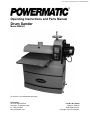
Operating Instructions and Parts Manual
Drum Sander
Model PM2244
For serial no. 2011222442682 and higher.
Powermatic
427 New Sanford Road Part No. M-1792244
LaVergne, Tennessee 37086 Edition 4 09/2020
Ph.: 800-274-6848 ECR 200813154321
www.powermatic.com Copyright © 2018 Powermatic
This .pdf document is bookmarked

2
1.0 IMPORTANT SAFETY
INSTRUCTIONS
WARNING – To reduce risk of injury:
1. Read and understand the entire owner's
manual before attempting assembly or
operation.
2. Read and understand the warnings posted on
the machine and in this manual. Failure to
comply with all of these warnings may cause
serious injury.
3. Replace warning labels if they become
obscured or removed.
4. This drum sander is designed and intended for
use by properly trained and experienced
personnel only. If you are not familiar with the
proper and safe operation of a drum sander, do
not use until proper training and knowledge
have been obtained.
5. Do not use this drum sander for other than its
intended use. If used for other purposes,
Powermatic disclaims any real or implied
warranty and holds itself harmless from any
injury that may result from that use.
6. Always wear ANSI Z87.1 approved safety
glasses or face shield while using this drum
sander. (Everyday eyeglasses only have impact
resistant lenses; they are not safety glasses.)
7. Before operating this machine, remove tie,
rings, watches and other jewelry, and roll
sleeves up past the elbows. Do not wear loose
clothing. Confine long hair. Non-slip footwear or
anti-skid floor strips are recommended. Do not
wear gloves.
8. Kickback occurs when the workpiece is thrown
towards the operator at a high rate of speed. If
you do not have a clear understanding of
kickback and how it occurs, DO NOT operate
this drum sander.
9. Wear hearing protection (plugs or muffs) during
extended periods of operation.
10. Do not operate this machine while tired or under
the influence of drugs, alcohol or any
medication.
11. Make certain the switch is in the OFF position
before connecting the machine to the power
supply.
12. Make certain the machine is properly grounded.
13. Make all machine adjustments or maintenance
with the machine unplugged from the power
source.
14. Remove adjusting keys and wrenches. Form a
habit of checking to see that keys and adjusting
wrenches are removed from the machine
before turning it on.
15. Keep safety guards in place at all times when
the machine is in use. If removed for
maintenance purposes, use extreme caution
and replace the guards immediately after
completion of maintenance.
16. Check damaged parts. Before further use of the
machine, a guard or other part that is damaged
should be carefully checked to determine that it
will operate properly and perform its intended
function. Check for alignment of moving parts,
binding of moving parts, breakage of parts,
mounting and any other conditions that may
affect its operation. A guard or other part that is
damaged should be properly repaired or
replaced.
17. Provide for adequate space surrounding work
area and non-glare, overhead lighting.
18. Keep the floor around the machine clean and
free of scrap material, oil and grease.
19. Keep visitors a safe distance from the work
area. Keep children away.
20. Make your workshop child proof with padlocks,
master switches or by removing starter keys.
21. Give your work undivided attention. Looking
around, carrying on a conversation and “horse-
play” are careless acts that can result in serious
injury.
22. Maintain a balanced stance at all times so that
you do not fall onto moving parts. Do not
overreach or use excessive force to perform
any machine operation.
23. Use the right tool at the correct speed and feed
rate. Do not force a tool or attachment to do a
job for which it was not designed. The right tool
will do the job better and more safely.
24. Use recommended accessories; improper
accessories may be hazardous.
25. Maintain tools with care. Keep conveyor and
abrasives clean for the best and safest
performance. Follow instructions for lubricating
and changing accessories.
26. Turn off the machine before cleaning. Use a
brush or compressed air to remove chips or
debris — do not use bare hands.
27. Do not stand on the machine. Serious injury
could occur if the machine tips over.

3
28. Never leave the machine running unattended.
Turn the power off and do not leave the
machine until it comes to a complete stop.
29. Remove loose items and unnecessary work
pieces from the area before starting the
machine.
30. Stand out of the path of workpiece when
feeding a board.
31. Always feed stock against the rotation of drum.
32. Keep hands clear when feeding parts onto the
conveyor. The part will be forced down as it
begins to feed, causing a pinching action
between the part and the conveyor bed. Never
reach into a running machine. Turn off sander,
allow it to come to a complete stop, and
disconnect from power, before attempting to
retrieve parts from beneath the drum.
33. Pay particular attention to instructions on
reducing risk of kickback.
34. Don’t use in dangerous environment. Don’t use
power tools in damp or wet location, or expose
them to rain. Keep work area well lighted.
35. Tighten the caster lock knobs before operating
the sander.
Familiarize yourself with the following safety notices used in this manual:
This means that if precautions are not heeded, it may result in minor injury and/or possible
machine damage.
This means that if precautions are not heeded, it may result in serious injury or possibly even
death.
SAVE THESE INSTRUCTIONS
2.0 About this manual
This manual is provided by Powermatic covering the safe operation and maintenance procedures for a
Powermatic Model PM2244 Drum Sander. This manual contains instructions on installation, safety precautions,
general operating procedures, maintenance instructions and parts breakdown. Your machine has been designed
and constructed to provide consistent, long-term operation if used in accordance with the instructions as set forth
in this document.
This manual is not intended to be an exhaustive guide to sanding methods, choice of stock, selection of
abrasives, etc. Additional knowledge may be obtained from experienced users or trade articles. Whatever
accepted methods are used, always make personal safety a priority.
If there are questions or comments, please contact your local supplier or Powermatic. Powermatic can also be
reached at our web site: www.powermatic.com.
Retain this manual for future reference. If the machine transfers ownership, the manual should accompany it.
Read and understand the entire contents of this manual before attempting assembly or
operation! Failure to comply may cause serious injury
WARNING: This product can expose you to
chemicals including lead which is known to the
State of California to cause cancer and birth
defects or other reproductive harm. For more
information go to http://www.p65warnings.ca.
gov.
WARNING: Drilling, sawing, sanding or
machining wood products generates wood dust
and other substances known to the State of
California to cause cancer. Avoid inhaling dust
generated from wood products or use a dust
mask or other safeguards for personal
protection.
Wood products emit chemicals known to the
State of California to cause birth defects or other
reproductive harm. For more information go to
htt
p
://www.
p
65warnin
g
s.ca.
g
ov/wood.

4
3.0 Table of contents
Section Page
1.0 IMPORTANT SAFETY INSTRUCTIONS ....................................................................................................... 2
2.0 About this manual .......................................................................................................................................... 3
3.0 Table of contents ............................................................................................................................................ 4
4.0 Specifications ................................................................................................................................................. 5
5.0 Setup and assembly ....................................................................................................................................... 6
5.1 Shipping contents ....................................................................................................................................... 6
5.2 Tools required for assembly ....................................................................................................................... 6
5.3 Unpacking and cleanup .............................................................................................................................. 6
5.4 Handwheel ................................................................................................................................................. 7
5.5 Infeed and Outfeed Tables ......................................................................................................................... 7
5.6 Caster lock knobs ....................................................................................................................................... 7
5.7 Dust Collection ........................................................................................................................................... 7
5.8 Installing Abrasives .................................................................................................................................... 7
6.0 Electrical connections .................................................................................................................................... 8
6.1 GROUNDING INSTRUCTIONS ................................................................................................................. 8
6.2 Extension cords .......................................................................................................................................... 9
7.0 Adjustments ................................................................................................................................................... 9
7.1 Depth scale ................................................................................................................................................ 9
7.2 Conveyor belt tension/tracking ................................................................................................................... 9
7.4 Inspecting drum alignment ....................................................................................................................... 10
7.5 Tension roller adjustment ......................................................................................................................... 11
7.6 Storage cabinet ........................................................................................................................................ 11
8.0 Operations .................................................................................................................................................... 12
8.1 Basic Operating Procedure ...................................................................................................................... 12
8.2 Controls and LED display ......................................................................................................................... 12
8.3 Drum motor operation .............................................................................................................................. 12
8.4 Feed Logic activation ............................................................................................................................... 12
8.5 Conveyor motor operation ........................................................................................................................ 12
8.6 Unit conversion ......................................................................................................................................... 12
8.7 Drum height setting .................................................................................................................................. 12
8.8 Emergency stop ....................................................................................................................................... 13
8.9 Switch safety key ...................................................................................................................................... 13
8.10 Setting depth of cut ................................................................................................................................ 13
8.11 Establishing drum height ........................................................................................................................ 13
8.12 Selecting conveyor rate .......................................................................................................................... 13
8.13 Maximum performance tips .................................................................................................................... 14
9.0 Maintenance ................................................................................................................................................. 15
9.1 Cleaning and lubrication ........................................................................................................................... 15
9.2 Drum maintenance ................................................................................................................................... 15
9.3 Conveyor belt replacement ...................................................................................................................... 15
10.0 Optional abrasives ..................................................................................................................................... 16
10.1 Abrasive dimensions for PM2244 ........................................................................................................... 16
11.0 Tracker kit .................................................................................................................................................. 17
12.0 Abrasives ................................................................................................................................................... 18
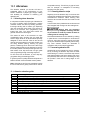
13.0 Troubleshooting the PM2244 Drum Sander ............................................................................................... 19
14.0 Replacement parts ..................................................................................................................................... 19
14.1.1 PM2244 Head Assembly I – Exploded View ....................................................................................... 20
14.1.2 PM2244 Head Assembly II – Exploded View ...................................................................................... 21
14.1.3 PM2244 Head Assembly III – Exploded View ..................................................................................... 22
14.1.4 PM2244 Head Assembly – Parts List .................................................................................................. 23
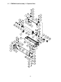
14.2.1 PM2244 Conveyor Bed Assembly – Exploded View ........................................................................... 26
14.2.2 PM2244 Conveyor Bed Assembly – Parts List .................................................................................... 27
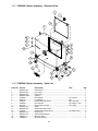
14.3.1 PM2244 Cabinet Assembly – Exploded View ..................................................................................... 28
14.3.2 PM2244 Cabinet Assembly – Parts List .............................................................................................. 28
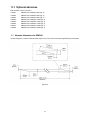
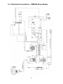
15.0 Electrical Connections – PM2244 Drum Sander ........................................................................................ 29
16.0 Warranty and service ................................................................................................................................. 30

5
4.0 Specifications
Model number .................................................................................................................................................... PM2244
Stock number ..................................................................................................................................................... 1792244
Motor and electricals:
Drum motor:
Motor type ................................................................................ totally enclosed fan cooled, induction, capacitor start
Horsepower .................................................................................................................................................. 1-3/4 HP
Phase ............................................................................................................................................................... single
Voltage ....................................................................................................................................................... 115V only
Cycle .................................................................................................................................................................. 60Hz
Listed FLA (full load amps) ................................................................................................................................. 14 A
Motor speed ............................................................................................................................................... 1720 RPM
Starting amps ...................................................................................................................................................... 54 A
Running amps (no load) .................................................................................................................................... 6.2 A
Start capacitor ................................................................................................................................. 300MFD 125VAC
Run capacitor ....................................................................................................................................... 50F 300VAC
Conveyor motor:
Motor type .................................................................................................................................... totally enclosed DC
Horsepower ................................................................................................................................................... 1/30 HP
Phase ............................................................................................................................................................... single
Voltage ........................................................................................................................................................ 100V DC
Listed FLA (full load amps) .............................................................................................................................. 0.45 A
Motor speed ................................................................................................................................................... 40 RPM
On/off switch ....................................................................................................................... magnetic, with safety key
Power cord................................................................................................................... 12AWG x 3C, 6 ft. (1830 mm)
Power plug installed .................................................................................................................................... 125V 15A
Recommended circuit and fuse/breaker size
1
..................................................................................................... 20A
Sound emission
2
...................................................................................................... 72 dB at 100cm; 74 dB at 50cm
Capacities:
Maximum board width ............................................... single pass – 22 in. (559 mm); two passes – 44 in. (1188 mm)
Maximum board thickness ................................................................................................................... 4 in. (102 mm)
Minimum board length ..................................................................................................................... 2-3/8 in. (60 mm)
Minimum board thickness ................................................................................................................ 1/32 in. (0.8 mm)
Materials:
Main body ...................................................................................................................................... cast iron and steel
Enclosed cabinet ................................................................................................................................................ steel
Drum ............................................................................................................................................ extruded aluminum
Extension tables ................................................................................................................................................. steel
Conveyor bed ............................................................................................................................................... cast iron
Handwheel .................................................................................................................................................... cast iron
Sanding drum:
Drum dimensions ....................................................................................................... dia. 5 in. x 22L (127 x 559 mm)
Drum speed ............................................................................................................................................... 1720 RPM
Sanding paper installed .................................................................................................................................... 80 grit
Drum elevation per one rotation of handwheel ............................................................................................. 2.12 mm
Conveyor:
Conveyor speed ............................................................................... infinitely variable within 0 to 10 FPM (0-3 MPM)
Conveyor bed dimensions ................................................................................. 23-1/4 x 15-5/32 in. (590 x 385 mm)
Conveyor height from floor....................................................................................................... 30-11/16 in. (780 mm)
Dust collection:
Dust port outside diameter ....................................................................................................................... 4” (100mm)
Minimum extraction volume required .......................................................................................... 800 CFM (23 CMM)
Dimensions:
Overall dimensions of shipping crate ....................................................45-5/8 x 23 x 50-1/4in. (1160x585x1277mm)
Overall dimensions, fully assembled (LxWxH) ..................... 42-1/4 x 37-11/16 x 49-1/2 in. (1073 x 957 x 1257 mm)
Weights:
Net weight .......................................................................................................................................... 328 lb. (149 kg)
Shipping weight ................................................................................................................................. 418 lb. (190 kg)
1
Subject to local/national electrical codes.
2
The specified values are emission levels and are not necessarily to be
seen as safe operating levels. As workplace conditions vary, this information is intended to allow the user to make a
better estimation of the hazards and risks involved only.

6
The specifications in this manual were current at time of publication, but because of our policy of continuous
improvement, Powermatic reserves the right to change specifications at any time and without prior notice, without
incurring obligations.
5.0 Setup and assembly
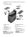
Figure 2
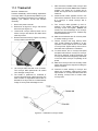
5.1 Shipping contents
See Figure 2.
1 Sander unit
1 Handwheel with handle – A
2 Extension tables – B
2 Infeed table brackets (L and R) – C
2 Outfeed table brackets (L and R) – D
2 Caster lock knobs – E
16 Socket hd. cap screws M8x20 - HP1
16 Lock washers M8 - HP2
16 Flat washers M8 - HP3
Read and understand all
assembly instructions before attempting
assembly. Sander must be disconnected from
power during assembly procedures. Failure to
comply may cause serious injury.
5.2 Tools required for assembly
Hex wrenches 4mm, 6mm
Open-end wrench 14mm
Straight edge (such as straight steel bar or carefully
jointed board)
5.3 Unpacking and cleanup
1. Inspect all contents for shipping damage.
Compare contents of shipping carton with the
contents list in this manual. Report any damage
or part shortages to your distributor.
Sander is heavy! Use an
assistant to help remove from pallet.

7
2. Remove any screws or blocks holding sander to
pallet. Carefully slide sander off pallet (NOTE:
There are internal blocks on the pallet securing
the sander – lift up on sander end to clear these
while sliding off pallet.)
5.4 Handwheel
1. Back off set screw (A
1
, Figure 2), and push
handwheel (A, Figure 2) down onto shaft as far
as it will go. Make sure set screw faces key on
shaft. Tighten set screw with 4mm hex wrench.
2. Install handle (A
2
) onto handwheel, and tighten
using 14mm wrench on the flats (A
3
).
Rotate handwheel clockwise to lower drum head;
counterclockwise to raise.
5.5 Infeed and Outfeed Tables
1. Attach table brackets (C,D, Figure 2) to sander
base with M8 screws and washers
(HP1,HP2,HP3). Tighten screws with 6mm hex
wrench.
NOTE: Longer brackets (C) mount to infeed
side, shorter brackets (D) to outfeed side. Each
bracket has left and right version. See Figure 2
for proper orientation.
2. Place extension tables (B) onto table brackets
(C) and insert screws and washers
(HP1,HP2,HP3). Note: Leave screws loose for
now.
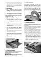
3. Place a straight edge across conveyor bed and
extension table. See Figure 3.
4. Position straight edge at two or three places
across width of table, as you adjust extension
table until it is slightly below surface of conveyor
belt.
5. Tighten screws.
6. Repeat for opposite table.
Figure 3
5.6 Caster lock knobs
Screw the caster lock knobs (E, Figure 2) into the
threaded holes on the side of the cabinet.
Always tighten the caster lock
knobs before operating the sander.
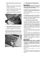
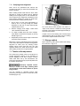
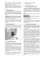
5.7 Dust Collection
Dust collection is mandatory for a safe work
environment and extended abrasive life. The
PM2244 is equipped with a 4-inch dust collection
port. Secure a 4-inch dust collection hose to the port
with a hose clamp (Figure 4), and connect to a high
volume dust collector (minimum 800 CFM). Note:
Dryer vent hose is not acceptable for this purpose.
Figure 4 (hose and clamp not included)
5.8 Installing Abrasives
Proper attachment of the abrasive strip to the drum
is critical to achieving top performance from your
drum sander.
An 80-grit, 3-inch wide abrasive strip is pre-installed
on the drum. Optional pre-cut abrasives of different
grits are also available; see sect. 10.0.
(TIP: If you are using an after-market abrasive, use
a new Powermatic-supplied abrasive as a template
to quickly cut a new strip. Alternatively, a diagram is
supplied in Figure 20 showing trim measurements.)
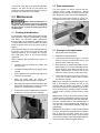
1. Press fastener lever (F, Figure 5) on outboard
(left) end of drum, and insert tapered end of
abrasive through slit in fastener, as shown.
Align tapered edge of abrasive strip with left
edge of drum. Insert enough strip so that the
right edge aligns with the reference notch; this
will ensure the proper length of strip to be
secured at the opposite end of the drum.
2. Release fastener lever to secure end of strip.
Figure 5

8
3. Begin wrapping abrasive around drum. The
tapered edge of strip end should follow edge of
drum.
4. Continue to wrap abrasive in spiral fashion by
rotating drum with one hand and guiding strip
with the other. See Figure 6.
Successive windings of strip must not have any
overlap. They should be flush with previous
windings or with a slight gap between.
The last winding should have a 1/16 to 1/8 in.
gap, before insertion into inboard fastener (see
Figure 7).
Figure 6
5. Press inboard take-up lever (G, Figure 7) and
insert trailing end of strip as far as it will go. If
necessary, trim tapered end of abrasive strip.
6. Release inboard take-up lever to secure strip.
All abrasive strips will stretch over time as they are
used, and may stretch enough to allow the take-up
lever to reach its lowest position so that it cannot
maintain tension on the strip. If this occurs, follow
the above procedures to reset the take-up lever.
Figure 7
6.0 Electrical connections
All electrical connections must
be done by a qualified electrician in compliance
with all local codes and ordinances. Failure to
comply may result in serious injury.
The PM2244 Sander is rated at 115-volt power only.
The sander comes with a plug designed for use on
a circuit with a grounded outlet that looks like the
one pictured in A, Figure 8.
Before connecting to power source, be sure switch
is in off position.
It is recommended that the sander be connected to
a dedicated 20 amp circuit with circuit breaker or
fuse. If connected to a circuit protected by fuses, use
time delay fuse marked “D”. Local codes take
precedence over recommendations.
6.1 GROUNDING INSTRUCTIONS
This machine must be grounded. In the event of a
malfunction or breakdown, grounding provides a
path of least resistance for electric current to reduce
the risk of electric shock. This tool is equipped with
an electric cord having an equipment-grounding
conductor and a grounding plug. The plug must be
plugged into a matching outlet that is properly
installed and grounded in accordance with all local
codes and ordinances.
Do not modify the plug provided - if it will not fit the
outlet, have the proper outlet installed by a qualified
electrician.
Improper connection of the equipment-grounding
conductor can result in a risk of electric shock. The
conductor with insulation having an outer surface
that is green with or without yellow stripes is the
equipment-grounding conductor. If repair or
replacement of the electric cord or plug is
necessary, do not connect the equipment-grounding
conductor to a live terminal.
Check with a qualified
electrician or service personnel if the grounding
instructions are not completely understood, or if
in doubt as to whether the tool is properly
grounded. Failure to comply may cause serious
or fatal injury.
Use only 3-wire extension cords that have 3-prong
grounding plugs and 3-pole receptacles that accept
the tool's plug.
Repair or replace damaged or worn cord
immediately.
2. Grounded, cord-connected tools intended for use
on a supply circuit having a nominal rating less than
150 volts:

9
This tool is intended for use on a circuit that has an
outlet that looks like the one illustrated in A, Figure
8. An adapter, shown in B and C, may be used to
connect this plug to a 2-pole receptacle as shown in
B if a properly grounded outlet is not available. The
temporary adapter should be used only until a
properly grounded outlet can be installed by a
qualified electrician. This adapter is not permitted in
Canada. The green-colored rigid ear, lug, and the
like, extending from the adapter must be connected
to a permanent ground such as a properly grounded
outlet box.
Figure 8
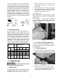
6.2 Extension cords
The use of extension cords is discouraged; try to
position machines near the power source. If an
extension cord is necessary, make sure it is in good
condition. When using an extension cord, be sure to
use one heavy enough to carry the current your
product will draw. An undersized cord will cause a
drop in line voltage resulting in loss of power and
overheating. Table 1 shows correct size to use
depending on cord length and nameplate ampere
rating. If in doubt, use the next heavier gauge. The
smaller the gauge number, the heavier the cord.
Ampere
Rating
Volts
Total length of
cord in feet
More
Than
Not
More
Than
120
240
25
50
50
100
100
200
150
300
AWG
00 06 18 16 16 14
06 10 18 16 14 12
10 12 16 16 14 12
12 16 14 12
Not
Recommended
Table 1: Extension cord recommendations
7.0 Adjustments
Disconnect sander from power
source before making adjustments.
7.1 Depth scale
The depth scale indicates distance between bottom
of sanding drum and top of conveyor belt.
Adjustment is performed by “zeroing” the scale.
1. With an abrasive strip on the drum, lower
sanding drum to where it touches top of
conveyor belt.
2. At this drum position, the depth scale pointer
should align with zero mark on scale. If it does
not, loosen screw (Figure 9) and raise or lower
pointer to align with zero on scale.
3. Retighten screw.
Note: Depending on desired accuracy, you may
need to repeat this process when installing different
abrasive grits.
This calibration of depth gauge establishes
“absolute” distance from conveyor belt to drum,
while the control panel allows setting of zero point
for relative distance.
Figure 9
7.2 Conveyor belt tension/tracking
Conveyor belt tension adjustment may be
necessary during the break-in period to compensate
for belt stretching.
7.2.1 Tension adjustment
1. Remove left side cover (Figure 10) by removing
two socket head screws with 4mm hex wrench.
Figure 10
2. Adjust take-up screw nuts (Figure 11) with a
17mm wrench. Do this on both sides of
conveyor to obtain approximately equal tension
on both sides of sanding belt when taut.

10
NOTE: Insufficient belt tension will cause
slippage of conveyor belt on drive roller during
sanding operation. The conveyor belt is too
loose if it can be stopped by hand pressure
applied directly to top of moving conveyor belt.
Excessive belt tension can result in bent rollers,
bent brackets, and/or premature wearing of
bushings or conveyor belt.
3. Reinstall left side cover when tensioning is
complete.
Figure 11
7.2.2 Tracking adjustment
A belt tracks correctly when it moves centrally on the
conveyor rollers without drifting to either side.
Tracking adjustments are made while conveyor belt
is running.
1. Make sure proper belt tension has been
achieved (see 7.2.1 Tension adjustment).
2. Turn on conveyor and set to maximum speed.
Watch for a tendency of conveyor belt to drift to
one side of conveyor. If it drifts, tighten or
loosen take-up screw nut on right side of
conveyor (Figure 11).
Note: Adjust take-up screw nut only 1/4 turn at
a time. Then allow time for belt to react to
adjustments before proceeding further.
Try to avoid over adjustments, as this may
affect belt tension. If tension is affected, if may
become necessary to remove left side cover
and use both take-up screw nuts to accomplish
tensioning and tracking.
7.2.3 Trackers
The sander comes equipped with “Trackers”,
ceramic guides that reduce the amount of
adjustments needed to keep the conveyor belt
tracked (centered) on the conveyor bed. See Figure
12. These guides have a magnetic backing to keep
them in place. If a Tracker wears through, it can be
reversed by turning it over. See sect. 11.0 Tracker
Kit for more information about re-setting trackers.
Figure 12
7.4 Inspecting drum alignment
The sanding drum must be parallel to conveyor bed
for proper machine operation. The sanding drum
comes pre-aligned from the manufacturer. If a
problem with drum alignment should occur, follow
the instructions below.
First, inspect the alignment with a gauge of some
kind. The following procedure uses a steel block as
a gauge.
1. Unplug sander from power source.
2. Open dust cover and remove abrasive strip
from drum.
3. Insert gauge (A, Figure 13) between drum and
conveyor bed at outboard side of drum.
Figure 13
4. With dust cover open, lower sanding drum while
slowly rotating drum by hand, until drum lightly
contacts gauge.
5. Remove gauge and place under drum at
inboard side.
6. If drum does not contact gauge equally on both
ends of drum, alignment is needed.
To align drum:
7. Turn adjustment dial (B, Figure 13) to raise or
lower outboard end of table. Follow directional
marks on dial (+ to raise).

11
7.4.1 Verifying drum alignment
Note: This is an operational test. Perform this
procedure only after you have become familiar with
sander operation.
When sanding boards wider than the drum, table
alignment is critical and table must be adjusted
exactly level to slightly lower on the outboard end.
This will prevent any ridges from developing in the
stock. Always check this on a piece of scrap wood,
as follows, before sanding the work piece.
1. Run a piece of scrap wood approximately 6”
wide by 30” to 40” long through the sander
sideways so that end of board extends past
outboard side of drum.
2. Without changing drum height, rotate board
180° and sand the same side.
3. If a ridge is visible where the drum overlaps,
lower table at outboard end slightly by turning
dial (B, Figure 13).
4. Repeat this process until the ridge is eliminated
and entire board is sanded.
TIP: Place a mark on adjustment dial to keep track
of how much dial rotation is needed to change drum
alignment for wider (over 22”) sanding. When
sanding narrow stock (less than 22”) turn dial
opposite direction the same amount as the initial
wide sanding so that drum is again parallel.
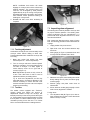
7.5 Tension roller adjustment
The infeed and outfeed rollers are tensioned to
provide downward pressure on the workpiece to
prevent slippage on the feed conveyor. Tension
rollers have been set by the manufacturer, but
should be inspected and may require adjustment as
the sander receives use.
Improperly adjusted tension
rollers (i.e. those set too high, rendering them
non-functional) could allow kickback of pieces
being sanded.
You can increase or decrease tension roller
pressure by turning the screws on the tension roller
brackets (Figure 14).
Figure 14
Too much tension roller pressure can result in a
“snipe” mark, which is a visible line running across
the width of the board and located approximately 2-
3/8” from end of board.
If snipe occurs on the leading end of board, adjust
outfeed tension roller. If the snipe occurs on trailing
end of board, adjust infeed tension roller.
7.6 Storage cabinet
Open cabinet by pulling latch outward and rotating
left, as shown in Figure 15.
Figure 15

12
8.0 Operations
Before using your drum sander, review the previous
sections on initial set-up and adjustment. Before
operating, make sure an abrasive strip is mounted
and a proper dust collection system is connected.
8.1 Basic Operating Procedure
1. Establish depth of cut.
2. Start dust collection system.
3. Start sanding drum.
4. Start conveyor and select feed rate.
5. Feed stock through machine.
To feed stock through the sander, rest and hold
board to be sanded on conveyor belt, allowing
conveyor belt to carry board into drum. Once stock
is halfway through, reposition yourself to outfeed
side of machine to receive and control board as it
exits.
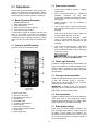
8.2 Controls and LED display
Figure 16 shows control panel functions.
Figure 16
A – Main power switch
B – Drum motor switch
C – Conveyor speed dial
D – Emergency stop (E-stop)
E – Unit selector
F – Zero depth reset
G – Conveyor speed indicator
H – Load indicator
I – Feed Logic ON indicator
J – Drum motor circle/ON indicator
K – Drum height
L – Drum height units
8.3 Drum motor operation
1. Connect power supply to machine. – Display
remains dark.
2. Turn on main power switch (A). – Display will
illuminate. Racetrack (G) may flash
continuously, indicating that emergency stop is
still engaged.
3. Rotate emergency stop (D) clockwise to
disengage stop.
4. Turn on drum motor by firmly pressing switch
(B) – Illuminated circle (J) will run, and “ON” will
illuminate.
Note: If drum motor does not start, make sure
conveyor speed dial (C) is set to OFF.
5. Load indicator (H) may illuminate. – When
motor is running without load, one bar may
illuminate. More bars are illuminated as load
increases.
6. Turn off drum motor switch (B). – “ON” will go
dark. Circle (J) will continue running for 5
seconds while drum slows to a stop. Then circle
(J) will stop running.
Do not open drum hood
until drum comes to a complete stop.
8.4 Feed Logic activation
If load on the sanding drum becomes excessive and
motor is overloaded or exceeds specified current,
“FEED LOGIC” (I) flashes and “ON” (I) lights up.
Conveyor will be automatically slowed to highest
efficient speed.
8.5 Conveyor motor operation
Rotate conveyor speed dial (C, Figure 15) clockwise
to start and increase speed of conveyor. –
Racetrack (G) will illuminate and run. Conveyor
speed will show inside racetrack.
IMPORTANT: If sander is shut off or E-stop is
engaged, conveyor speed dial must be returned to
OFF position in order to restart sander.
8.6 Unit conversion
Toggle unit selector button (E) to select imperial or
metric units. Units for drum height and conveyor
speed will change accordingly on the display. When
power is turned off, units default to imperial.
8.7 Drum height setting
Lower drum until it just contacts workpiece, then
push zero depth reset button (F, Figure 16) to zero
the setting of drum height from workpiece. The
handwheel is then used to lower the drum in exact
increments for each pass, by viewing the depth on
the control display (K).

13
When handwheel is rotated to move drum
downward below zero point, a negative sign will
appear before the depth number (K).
NOTE: Drum height will remain in control panel
memory if E-stop button is pressed. Drum height will
not remain in memory if main power switch is turned
OFF.
8.8 Emergency stop
Press E-stop button (D, Figure 16) to shut down all
machine operations. When E-stop is pressed, drum
motor stops and “ON” (J) goes dark on display.
Conveyor motor also stops, and racetrack (G)
flashes.
IMPORTANT: The E-stop remains engaged until it
is rotated clockwise for release. Also, the conveyor
speed dial (C, Figure 16) must be returned to OFF
position before restarting machine.
The E-stop is designed for emergency shut-off.
Under normal circumstances, use the other
switches on the control panel to turn off machine
functions.
8.9 Switch safety key
To prevent unauthorized use of sander, turn off main
switch and pull out safety key (Figure 17). Store key
in a safe place. Key must be reinserted to start
sander.
Figure 17
8.10 Setting depth of cut
Adjusting the drum sander for proper contact
between abrasive and stock determines the depth
of cut. The depth of cut is controlled by the height
adjustment handwheel.
It may take some experimentation to determine the
proper depth of cut, given the variables of abrasive
grit, type of wood, and feed rate. For best results,
use scrap wood to practice sanding and to develop
skill and familiarity with the machine before doing
finish work.
A combination of several variables will determine
proper depth of cut to use, including the following:
1. Abrasive type and grit size.
2. Width of piece being processed.
3. Hardness of piece.
4. Feed rate of conveyor belt.
8.11 Establishing drum height
A good rule of thumb when sanding with grits finer
than 80 is to place the stock to be sanded under the
drum and lower drum until it contacts the stock.
Drum should still rotate by hand. Without changing
drum height, finish feeding the stock under the
sander.
Start sanding drum and sand the stock at that same
position.
Do not start drum while in
contact with stock.
For sanding with grits coarser than 80, you can
lower the drum slightly.
Always maintain control of stock. Through practice
you will learn the proper depth of cut considering the
variables above.
8.12 Selecting conveyor rate
A faster feed rate allows faster sanding but fewer
revolutions of the drum per inch of sanding. A slower
feed rate provides more revolutions of the drum per
inch of sanding to allow a greater depth of cut and
smooth sanding.
Begin experimenting with feed rate set to about 40%
to 50% of maximum. The best feed rate will depend
on a number of factors, including type of stock, grit
and depth of cut used, and whether the stock is fed
directly in line with the conveyor bed or at an angle.
If the drum motor is lugging down, if the conveyor
belt is slipping, or if you observe a ripple effect on
the stock, slow the feed rate. If the finish is smooth
and the machine is not overworking, you can
experiment using a faster feed rate.
The Feed Logic control continuously monitors the
load on the drum motor, and automatically regulates
the speed of the conveyor motor to maintain highest
feed rate without overload. When “Feed Logic”
flashes and “ON” illuminates on the display (I, Figure
16), the Feed Logic control has detected too great a
depth of cut and/or too fast a feed rate.
If load on the drum motor increases, Feed Logic will
decrease the conveyor feed rate and will stop the
conveyor under extreme conditions. If load on the
drum motor decreases, Feed Logic will increase the
feed rate but will not increase it faster than the
speed the user has preset on the dial.
The best and most consistent finish will be achieved
if the conveyor does not change speed during
operation. A change in conveyor speed may affect
the finish surface. If the finish is affected, make
another sanding pass without changing any
settings.

14
If the finish is still affected, make adjustments by
slowing the conveyor and/or decreasing the depth
of cut and run the stock through again.
Also try a faster feed rate or less depth of cut if the
stock you are working begins to show burn marks.
With cherry, hard maple or other hardwoods, using
a shallower depth of cut and a faster feed rate will
help minimize burn marks.
Slightly angling the stock as it is fed into the machine
will also help prevent burning the stock.
Because of the wide range of variables, it is
important to experiment with your specific
conditions and make adjustments to achieve
optimum feed rate. If problems occur, first inspect
and adjust feed rate, referring to sect. 12.0
“Troubleshooting.”
8.13 Maximum performance tips
The versatility designed into the PM22-44 drum
sander allows it to be used for a variety of tasks that
will boost return on your investment. For example, it
will speed up fine sanding work often done with
slower, dust-generating hand sanders, and will
achieve fine thickness adjustments not possible on
some sanders. It can be used to surface figured
woods – bird’s eye or curly maple, for example –
which can be damaged if fed through a planer.
Learning how to use its adjustments and controls
will allow you to fine-tune the machine for maximum
results. The best results come from experimenting
with different abrasive grits and machine
adjustments to fit the job at hand. Following is a list
of useful tips which can help you improve
performance of your sander.
8.13.1 Dust collection
When connecting dust collectors, remember that
straight pipe will not restrict airflow as much as
flexible tubing. Y’s and elbows will restrict airflow
less than T’s. Also, a hose smaller than 2-1/2”
diameter should not be used.
8.13.2 Multiple-piece sanding runs
When abrasive planing (or thickness sanding) a run
of similar pieces that you want to have the same
thickness, it is best to determine the thickness of the
thinnest piece and process all pieces to that same
thickness in one session. Be aware that the sander
will remove cups and crowns in the workpiece;
consider this when measuring and processing stock
to the same thickness.
8.13.3 Simultaneous multiple pieces
When sanding multiple pieces simultaneously,
make sure to stagger (step) the pieces across the
width of the conveyor belt. This provides better
contact with the tension rollers. Try to process only
multiple pieces of similar thickness.
If there is a significant thickness difference, the
thinner pieces can slip on the conveyor belt if they
do not contact the tension rollers. Also note that
pieces thicker than 3/4” should be longer than the
minimum normally recommended to prevent tipping
of the stock.
8.13.4 Edge sanding
When edge sanding, the sander will mimic the
opposite edge of the stock which is lying on the
conveyor belt. Because of this, it is important for the
stock edge to have been ripped at the proper angle
to the face before the sanding process. When edge
sanding stock that is less than 3/4” wide or more
than 2” high, it is good procedure to stack and clamp
several pieces together to prevent them from
slipping or tipping on the conveyor belt.
8.13.5 Sanding imperfect stock
When sanding stock with a cup or crown, place the
crown up. This will stabilize the stock to help prevent
tipping or rocking during sanding. After the crown
has been removed and the top is flat, turn the stock
over and sand the opposite side. To avoid personal
injury, take special care when sanding stock that is
twisted, bowed, or otherwise varies in thickness
from end to end. If possible, support such stock as
it is being sanded to keep it from slipping or tipping.
Use extra roller stands, help from another person,
or hand pressure on the stock, to minimize
potentially hazardous situations.
8.13.6 Face frames and raised panel
doors
It is very important to have the proper abrasive
contact when doing this type of sanding. If the
machine is set to take an excessive depth of cut, the
result can be a gouge or dip as the drum goes from
sanding the rails at full width to sanding just a few
inches of width on the stiles. To prevent this make
sure, when using abrasives finer than 80 grit, that
the drum is in contact with the wood but can still be
spun by hand. If there is room, angling the stock on
the conveyor belt can also help. Slowing the
conveyor feed when coming to a rail in the stock can
help prevent a dip or gouge. This allows the
abrasive to work the wider width with less effort, and
to achieve better consistency of the finished
surface.
8.13.7 Stock feeding angle
Some pieces, because of their dimensions, will
need to be fed into the machine at a 90° angle
(perpendicular to drum). However, even a slight
offset angle of stock will provide for more effective
stock removal. The optimum feeding angle for stock
removal is about 60°.
Angling the workpiece for stock removal provides
other advantages, such as less loading of certain
areas of the drum due to glue lines or mineral
streaks in the stock, more even wear of abrasive
strips, potentially faster feed rates, and lighter loads

15
on the motor. Note that to get the best final finish,
however, the stock should be fed through the
machine so it will be sanded in line with the grain of
the wood on the final one or two passes.
9.0 Maintenance
Before doing maintenance on
the machine, disconnect it from the electrical
supply by pulling out the plug or switching off
the main switch. Failure to comply may cause
serious injury.
9.1 Cleaning and lubrication
For best results, make cleaning the sander a regular
shop procedure. Allowing excess build-up of dust
and debris can adversely affect performance
through loading of the abrasives, slippage on the
conveyor table, and/or the accumulation of material
inside the drums which can throw off the center of
balance.
Leave the dust collector on when cleaning dust from
the drums. Also brush the conveyor belt after
cleaning operations. If not cleaned, the conveyor
belt could allow stock to slip during sanding
operations.
NOTE: Bearings are pre-sealed and require no
lubrication.
Lubricate conveyor bushings as needed, and
check for wear.
Lubricate elevating leadscrew (A, Figure 18) as
needed.
Clean sawdust from abrasive strip and brush
dust from conveyor belt.
Keep gib areas clean (B, Figure 18).
Periodically lubricate gibs lightly with grease.
Blow dust from motors and switches. Blow dust
from inside of sanding drum, which may cause
vibration or offset the center of balance.
Check all set screws for tightness on parts such
as bearings, conveyor bed, and couplings.
Figure 18
9.2 Drum maintenance
The drum should not require removal from the
machine under normal circumstances. Should
maintenance ever become necessary, the drum has
been designed for easy removal and replacement.
Remove four socket head screws (C, Figure 19).
Carefully lift out drum with coupling (D) attached.
Figure 19
9.3 Conveyor belt replacement
1. Disconnect sander from power.
2. Raise drum to highest position.
3. Loosen take-up screw nuts (Figure 11) on both
sides of conveyor to relieve belt tension, and
slide the driven roller fully inward.
4. Remove three (3) screws that attach conveyor
table to base. Lift up conveyor table and remove
it from machine. Avoid tearing the belt on any
edges underneath the conveyor bed. Do not
allow the Trackers to drop, as they may break.
5. Install new belt along with trackers (see sect.
11.0), and re-install conveyor table. Tension
and track the new belt.
Note: If the conveyor belt continually tracks to one
side of the machine, reversing the belt on the
conveyor bed may remedy the problem. To make
sure the conveyor bed is not twisted, place a level
on the conveyor bed. Level the machine if needed.
If there is still a problem, proceed with the steps
below:
Step 1: Check conveyor drive roller and driven roller
to make sure they are parallel to surface of conveyor
bed. To do this, first center conveyor belt on the bed.
Then lay a straight-edge on the exposed edge of
conveyor bed on left (outboard) side, extending it
over the roller. Note distance between roller and
straightedge.
Step 2: Now repeat Step 1 on right (inboard) side of
conveyor. Compare the measurements from side to
side. If they are not equal, loosen one of the
brackets that hold the roller in place. Tip this bracket
until distance between roller and straight-edge are
equal from side to side, then tighten bracket.

16
10.0 Optional abrasives
Each abrasive comes in pack of 3.
1792201 PM2244 Precut Abrasive 36G (qty. 3)
1792202 PM2244 Precut Abrasive 60G (qty. 3)
1792203 PM2244 Precut Abrasive 80G (qty. 3)
1792204 PM2244 Precut Abrasive 100G (qty. 3)
1792205 PM2244 Precut Abrasive 120G (qty. 3)
1792206 PM2244 Precut Abrasive 150G (qty. 3)
1792207 PM2244 Precut Abrasive 180G (qty. 3)
1792208 PM2244 Precut Abrasive 220G (qty. 3)
10.1 Abrasive dimensions for PM2244
Use this diagram to cut after-market abrasive strips to fit (or use a new Powermatic-supplied strip as a template).
Figure 20

17
11.0 Tracker kit
Stock No.: PM2244-213
Trackers dramatically reduce tracking adjustments
of conveyor belts. They are already installed on your
sander. The following information is for resetting or
replacing your trackers, should that become
necessary.
1. Disconnect power to sander.
2. Raise drum as high as it will go, and remove
side cover (see Figure 10).
3. Loosen both conveyor take-up screw nuts to
relieve conveyor belt tension and slide driven
roller fully inward.
4. Remove the three screws (A, Figure 21) holding
conveyor table to sander base.
Figure 21
5. Lift conveyor table and slide it out of sander.
Turn conveyor table upside down. Be careful
not to damage conveyor belt.
6. The tracker is positioned on underside of
conveyor bed near driven roller (Figure 22). The
back of tracker is magnetized and will stick to
side wall of conveyor bed. Do not install tracker
if edge of conveyor belt is damaged or torn.
7. With first tracker installed, slide conveyor belt
into bottom slot of tracker. Note: When installed
properly, only bottom lip of tracker will be
visible. The top slot can be used if bottom slot
wears out.
8. Install second tracker opposite the first. Use
both trackers unless the second one does not
fit in conveyor or unless conveyor belt is
damaged.
9. Turn conveyor table right-side up and re-
position it onto sander. Re-attach three (3)
mounting screws and tighten. Caution: Be
careful not to knock tracker(s) out of conveyor
bed when turning conveyor over. Trackers may
break if allowed to fall.
10. Make sure all switches are off. Connect power
to sander and plug in motor.
11. Tension conveyor belt using take-up screw
nuts. If both trackers are installed, it is very
important to have equal tension on both sides
of conveyor belt. Tighten take-up screw nuts on
both sides until equal tension is obtained.
12. To check tension, turn on conveyor full speed
and place both hands on conveyor. If conveyor
belt can be stopped, continue tensioning until
conveyor belt cannot be stopped by both hands
on the belt while conveyor is operating at full
speed.
13. Make sure conveyor belt runs smoothly inside
tracker slot and that the magnet is holding the
tracker in position.
14. Continue to watch tracking of conveyor and
adjust only if necessary, making sure to keep
equal tension on conveyor belt at all times and
not allowing conveyor belt to buckle under
conveyor bed.
Figure 22 – Underside of conveyor shown

18
12.0 Abrasives
The abrasive material you choose will have a
substantial effect on the performance of your
sander. Variations in paper type, weight, coating
and durability all contribute to achieving your
desired finish.
12.1 Selecting drum abrasives
It is important to select the proper grit of abrasive for
the type of sanding being performed to achieve
maximum results. As with any sanding operation,
first begin sanding with a coarser grit, depending
upon the roughness of the stock or the amount of
stock to be removed. Then progressively work
toward finer grits. The chart below shows the
general uses for the various grits.
The amount of stock to be removed is a major
consideration when choosing the grit grade with
which to begin. Grits 24, 36, 50 and 60 are primarily
designed for stock removal. Grits 24 and 36 will
remove the most material in one pass, whether you
are doing abrasive planing, cleaning up glued
panels, or flattening stock. Grits from 100 through
220 are primarily finishing grits designed to remove
the scratch pattern from the previous grit used. For
best results, never skip more than one grit grade
when progressing through a sanding sequence.
For fine work, such as furniture, try not to skip any
grit grades during the sanding process.
In general, premium quality abrasives will produce a
better finish with a less noticeable scratch pattern.
Note: Grits that are too fine can sometimes burnish
the wood and leave a glossy surface which will not
accept stains evenly. This will vary by type of wood.
Oak, for example, is susceptible to burnishing
because of its open pores.
12.2 Cleaning abrasive strips
Regularly clean the abrasive strip on the drum with
commercially available cleaning sticks, following the
manufacturer’s directions. When cleaning, also
brush the stick crumbs from the drum while it is still
rotating.
In some cases, heavy loaded areas can be removed
with Plexiglas held on edge over the rotating drum.
Always wear eye protection
while performing sandpaper cleaning, and take
all precautions to avoid any contact of hands or
clothing with the rotating drum.
Cloth-backed abrasives can be cleaned by soaking
in paint thinner or mineral spirits for 20 minutes to
one hour, then using a brush to remove any build-
up. Dry the abrasive strips completely before using.
Any used solvents should be discarded in
compliance with environmental regulations.
12.3 Increasing abrasive life
Abrasive life can be increased not only by cleaning,
but by removing the abrasive strip from the drum
and reversing it. To do this, remove the strip and use
what was the trailing end as the starting end on the
left (outboard) side of the drum. Reversing the strip
will provide a fresh set of cutting edges on the
abrasive.
12.4 Abrasive selection guide
Grit Common Application
24 Abrasive planing, surfacing rough-sawn boards, maximum stock removal, glue removal.
36 Abrasive planing, surfacing rough-sawn boards, maximum stock removal, glue removal.
50 Surfacing and dimensioning boards, truing warped boards
60 Surfacing and dimensioning boards, truing warped boards.
80 Light dimensioning, removal of planer ripples.
100 Light surfacing.
120 Light surfacing, minimal stock removal.
150 Finish sanding, minimal stock removal.
180 Finish sanding only, not for stock removal.
220 Finish sanding only, not for stock removal.
Table 2

19
13.0 Troubleshooting the PM2244 Drum Sander
Symptom Possible Cause Correction *
Drum motor won’t start
when ON button is
pushed.
No incoming current. Check connections at plug or circuit panel.
Safety key missing from switch. Install safety key.
E-stop still engaged (racetrack is
flashing).
Disengage E-stop by rotating clockwise.
Conveyor speed dial not reset after
using E-stop (racetrack is flashing).
Turn speed dial to OFF position, then try
starting machine.
Low voltage. Check power line for proper voltage.
Open circuit in motor or loose
connection.
Inspect all lead connections on motor for
loose or open connections.
Motor will not start: fuses
blow or circuit breakers
trip.
Short circuit in line cord or plug. Inspect cord or plug for damaged insulation
and shorted wires.
Short circuit in motor or loose
connections.
Inspect all connections on motor for loose or
shorted terminals or worn insulation.
Incorrect fuse or circuit breaker in
power line.
Install correct fuse or circuit breaker.
Motor overheats. Air circulation through motor restricted. Clean motor fan with compressed air to
restore normal air circulation.
Motor overloaded (Feed Logic not
functioning properly.
Have controls inspected and repaired.
Motor stalls, resulting in
blown fuses or tripped
circuit.
Short circuit in motor or loose
connections.
Inspect connections on motor for loose or
shorted terminals or worn insulation.
Low voltage. Correct low voltage conditions.
Incorrect fuse or circuit breaker in
power line.
Install correct fuse or circuit breaker.
Loud, repetitive noise or
vibration coming from
machine.
Fasteners loose. Inspect fasteners and tighten where needed.
Motor fan is hitting cover. Tighten fan or shim fan cover.
Machine not level. Place sander on level floor; shim if needed.
Conveyor motor will not
run.
Conveyor speed dial not reset after
using E-stop.
Turn speed dial to OFF position, then try
starting machine.
Drum motor shuts off
when finger leaves drum
motor on/off switch.
Not pressing drum motor switch long
enough.
Press and hold for at least 1 second.
Conveyor speed dial not reset after
using E-stop or switching off main
switch.
Turn speed dial to OFF position, then try
starting machine.
* WARNING: Some corrections may require a qualified electrician.
Table 3
14.0 Replacement parts
Replacement parts are listed on the following pages. To order parts or reach our service department, call 1-800-
274-6848 Monday through Friday, 8:00 a.m. to 5:00 p.m., CST. Having the Model Number and Serial Number of
your machine available when you call will allow us to serve you quickly and accurately.
Non-proprietary parts, such as fasteners, can be found at local hardware stores, or may be ordered from
Powermatic. Some parts are shown for reference only, and may not be available individually.

20
14.1.1 PM2244 Head Assembly I – Exploded View
Page is loading ...
Page is loading ...
Page is loading ...
Page is loading ...
Page is loading ...
Page is loading ...
Page is loading ...
Page is loading ...
Page is loading ...
Page is loading ...
Page is loading ...
Page is loading ...
-
 1
1
-
 2
2
-
 3
3
-
 4
4
-
 5
5
-
 6
6
-
 7
7
-
 8
8
-
 9
9
-
 10
10
-
 11
11
-
 12
12
-
 13
13
-
 14
14
-
 15
15
-
 16
16
-
 17
17
-
 18
18
-
 19
19
-
 20
20
-
 21
21
-
 22
22
-
 23
23
-
 24
24
-
 25
25
-
 26
26
-
 27
27
-
 28
28
-
 29
29
-
 30
30
-
 31
31
-
 32
32


Powermatic PM2244 Drum Sander 1-3/4HP 115V 1792244 User manual
- Type
- User manual
- This manual is also suitable for
Ask a question and I''ll find the answer in the document
Finding information in a document is now easier with AI
Related papers
-
Powermatic PM2244 Drum Sander, 1-3/4HP, 115V User manual
-
Powermatic 1791292K User guide
-
-
-
-
-
-
-
-
Other documents
-
Bushnell Resetting Elite adjustments Owner's manual
-
King Canada KC-16-1-D User manual
-
General International 15-150 M1 User guide
-
JET 723544OSCK Owner's manual
-
JET JWDS-2244 Owner's manual
-
King Canada KC-26-1-D User manual
-
Craftex CX Series CX509 Owner's manual
-
-
-