Page is loading ...

SR-3000: 126” X 9”X 8.5” 50 LBS
SR-1000: 43.5” X 9” X 8.5” 21.5 LBS
What is included in The RAQ Solar Mounng Kits?
SR-3000 Includes
Self squaring 3 Panel Rails with adjustable panel clamps, adjustable
anchor bases, ashing and all hardware to assemble
SR-1000 Includes
Self squaring 1 Panel Rail, with adjustable panel clamps, adjustable
anchor bases, ashing and all hardware to assemble
SR-0700 Start Bracket Kit
For a stand alone unit or to start a row, and grounding for stand alone
or row of rails (up to 18 max.)
SR-0400 Addional Wind Zone Kit
4 addional ashing, 4 adjustable anchor bases, end clips and all hard-
ware to assemble.
SR-0900 Micro Inverter Bracket Kit
3 Micro inverter brackets and all hardware to assemble
What will I need to Install The RAQ Solar Mounng
Kits?
Safety Equipment:
Ladders, eye protecon , hard hats and all fall protecon
Tools:
1/2” Socket and Driver (with extra charged baeries on hand)
3/8” Cold Rolled Drill Bit (incase of odd anchor feet placement, or
misaligned raer spacing)
4 1/2” Long Wood Drill Bit (for predrilling lag bolt penetraons)
Open by removing strap that is securing box with box cuer
Unpack Contents and verify order is accurate
Familiarize yourself with the various components and
prepare kit for installaon
Take all equipment on roof and set up for installaon
Cut zip e on assembly
Installation
Instructions
1
3
2
4

Open the assembly unl bi-fold center brace (s) is
straight, ensure holes are lined up for securing
Place T23 Bolt into predrilled hole by bi-fold hinge en-
suring it is lined up with the predrilled hole below and
ghten.
Locate all squaring arms; connected to the underside
of cross brace, rotate them out to the point where
they naturally land on the top of rail.
Secure all of the squaring arms individually with pre-
installed T23, ghten fully by drilling with 1/2” socket
it into preposioned hole.
Locate Start Brackets and aach onto le end
*Remember Start brackets are only used at the begin-
ning of a row (on the farthest le side of the row )or to
complete a stand alone unit.
Using drill with 1/2” socket, secure by ghten bolt fully.
*Remember Start brackets are only used at the begin-
ning of a row (on the farthest le side of the row )or to
complete a stand alone unit.
5
6
7 8
9 10

Next we must locate the roof raers. An industry stand-
ard way to locate roof raers is to ulize a hammer and
strike the roof while listening for sound dierences.
If the raer is missed when predrilling minor adjust-
ments can be made to properly locate the raer, these
small adjustments will be protected by the anchor foot
ashing to be installed later or you can use roong caulk
to seal the unused hole.
If combining RAQ’s into a row now is the me to inter-
connect the rails. (If you are only building a stand-
alone unit you may move on to next step) Connect to-
gether by sliding male end into female end of rails.
Tighten aached bolts completely with a driver and
1/2” socket. As many as 18 PV’s can be assembled in a
row before you must start a new row. (Only 1 start
bracket kit needed per row).
A second row requires there is proper spacing between
rows, (generally 27” when using the standard 60 cell
panel)
Keep in mind: The preposioned slot available on the rail
allows for up to 3” of adjustment of the anchor foot le
or right, to compensate for most of all adjustments due
to roof raer spacing. Placement of the bolt for securing
onto rail always goes in lower slot.
Keep in mind: The anchor bases also allow for vercal
adjusts to compensate for variances in roof levels,
while maintaining minimum height distance from roof
to the boom of the solar panel
Before we secure rail (s) into roof we must be aware of
a few things. First, anchor bases will always point up to
the peak of the roof. Secondly, placement of prein-
stalled anchor bases may need to be relocated
(depending on raer spacing on roof being installed
onto and wind and snow load capacies) . Preassem-
bled anchor base spacing is set for 24” on center.
Now is the me to congure raer spacing for proper
installaon of anchor bases onto rail to be lined up with
the raer spacing. Predrilled holes are placed along the
rail based upon, 16”, 24”, 32”, 48’, even 72” & 96” spans
are available. If raer spacing does not line up with the
preassembled holes available feel free to drill a hole (s)
using cold rolled drill bit . Keep in mind this reduces self-
leveling abilies so please ensure placement before hole is drilled.
11
12
13
14
15 16

Each RAQ comes with pre drilled locaons for the in-
verters which allows for a multude of spacing adjust-
ments for cord management. Simply install inverter
with the T23 bolt provided. This bolt can be moved to
any predrilled locaon in the main rail. Once place-
ment is established set bolt but do not ghten. Slide
the inverter under the bolt, then ghten the bolt to
hold the inverter in place, the inverter may be posi-
oned on either side of the rail . Connect inverter ca-
bles to inverters according to manufacture suggesons.
A zip e is also included for cable management to be run down inside of C
Channel.
Once the anchor foot has been properly bolted to
the roof raers water protecon or roof ashing
can be placed. Unlike the majority of other rack-
ing systems, The RAQ, uses a Mechanical method
of water proong, not a chemical protecon.
Leveling the racking for mulple units in a row usual-
ly requires the installer to view the array from the
ground to determine if it is level based on aesthecs.
Please use a tape measure, string line, and a discern-
ing pair of eyes to make certain the array looks good
from every angle.
Begin by inserng the ashing under the shingle line
above the anchor foot locaon. Connue to rotate
the ashing under the shingle line unl it is fully seat-
ed over the anchor foot. Once ashing is seated over
the anchor base bend the tabs to secure the ashing
around the anchor foot. If you have a second row
below be sure there is proper spacing between rows,
(generally 27” when using the standard 60 cell panel)
Once the raer locaon is determined based on your
installaon layout conguraon predrilled holes
should be made with the 4 1/2” drill bit in the loca-
on where anchor bases will be installed into roof
raers. Note: Anchor bases may need addional ad-
justments o the rail before they line up with raers.
Start from the top work your way to the right, then
below. If you have a second row below be sure there
is proper spacing between rows, (generally 27” when
using the standard 60 cell panel)
To adjust leveling simply locate the anchor base that
need adjusng and modify anchor base ll it is ush
with the roof surface.
Note: Occasionally, one side of the installaon may be
more visible
Next prepare PV ‘s to be installed on leveled racking
17
18
19
20
21
22

Once aached, set PV down and center. Keep in mind:
The start bracket panel clamps must be adjusted uni-
formly; they allow for 3” of variance, determined by in-
stallaon conguraon. Secure upper and lower panel
clamps on the le side ONLY. To secure the # 1 PV mod-
ule, use the ½” socket on the top panel clamp, start by
securing the panel clamp on the start bracket side( le).
Then slide the panel clamps from the right side to the le
thus aligning the panel clamp over the frame of the mod-
ule. Only secure the panel clamps on the frame of PV
module.
Starng from the top row, from le to right, place the
#1 PV module in the portrait posion and place the
module onto the 1st RAQ unit (under panel clamps on
start brackets ) and hold up on right side to aach PV
to inverter cables.
Leveling the solar array for mulple units in a row re-
quires the installer to view the array from the ground to
determine if it is level; based on aesthecs. Visual exami-
naon aer PV’s installed adjustments made based on
installers eye to judge what anchors need to be adjusted.
Occasionally, one side of the array may be more visible
from the ground or even from a second-story window.
Connue using tape measure, string line, and a discern-
ing pair of eyes to make certain the array
looks good from every angle.
Before securing the next set of panel clamps onto 1st
PV bring in PV module # 2 onto the next RAQ unit to
the right. Install just like #1; by seng and lng le
side of PV in portrait posion under panel clamps,
aach PV to inverter and set down. Before securing #
2 PV to RAQ be sure it is ush and level with #1 PV.
Then secure the 1 & 2 PV module by securing the next
set of panel clamps upper rst, then lower clamp on
panel. Repeat for up to 18 panels before needing to
23
24
25
26

SP-1000
The Solar PaQ
Solar Panel + Inverter + Universal Roof Mount Racking
UPC: 861150002609
Microinverter Instructions
COMPANY PROFILE
01
1. INTRODUCTION
02
1.1 Prefix 02
1.2 Grid‐tied PV System 02
1.3 How to Use This
Manual
1.4 Label
02
2. SAFETY INSTRUCTION
02
3. FCC COMPLIANCE 03
4. INSTALLATION
03
04
Parts Included
Other Parts and Tools Required
Lightning Surge Suppression
Installation Procedure
Step 1 ‐ Install the AC Branch Circuit Junction Box
Step 2 ‐ Attach the BDM‐250 to the Racking
Step 3 ‐ Connect the BDM‐250 Wiring Harnesses
Step 4‐ Ground the System
Step 5 ‐ Complete the connection map and connect the PV Modules
5. COMMISSIONING
6. OPERATING INSTRUCTIONS
7. TROUBLRSHOOTING MAINTENANCE
8. SPECIFICATION
9. WARRANTY AND PRODUCTION INFORMATION

SP-1000
The Solar PaQ
Solar Panel + Inverter + Universal Roof Mount Racking
UPC: 861150002609
Microinverter Instructions
COMPANY PROFILE
Northern Electric & Power Inc. (NEP) was founded in the United States and has manufacturing and R&D
facilities in China. The mission of the company is to develop cutting‐edge clean energy technologies and
provide state‐of‐the‐art solar inverter products to its customers. The first round of investment to the
company was US$20 Million, with a planned total investment of US$50 Million. The company is
headquartered in the city of Tsingtao, a major industrial center andtrading port in the northeastern China.
The company campus occupies more than18 acres in the Tsingtao Export Processing Zone, and has more
than 650,000square feet building space. The campus is planned to be connected through amicro smart grid
demo community and powered by electricity from solar, windand micro turbines. Outside China, the
company has operation offices in Chicago,U.S. and Vancouver, Canada.
The technology founders of the company are well‐known experts in the fields ofpower electronics,
automatic control, signal processing, and communications.
Each of the founders has multiple U.S. and world patents in their specialty areas.They received Ph.D.
degrees from top universities in North America, and each has
more than 10 years engineering and management experiences in leading U.S.companies.
NEP has a complete product line of grid‐tied solar inverters, including 250W~500W micro inverters,
1.5kW~5kW single phase solar inverters, and 10kW~500kW three‐phase solar inverters. Field deployment
results demonstrated high system efficiency and reliability of NEP solar inverters.
NEP is committed to develop Clean, Reliable, Affordable and Efficient (CARE)products for worldwide
customers.
1. INTRODUCTION
1.1 Prefix
Dear customer, thank you for choosing the BDM‐250 micro inverter from NEP.
We hope you will find our products meet your need for renewable energy.
Meantime, we appreciate your feedback regarding our products.
1.2 Grid-tied PV System
Grid‐tied PV system consists of PV panels, grid‐tied inverter and junction boxes. The DC output from the PV
panels is converted into AC energy and feedback to the grid through the BDM‐250. BDM‐250 series PV micro
inverter contains isolation transformer with basic insulation between PV input and AC grid output. The PV
panel terminals on BDM‐250 shall not be earthed via external wiring, for BDM‐250 connects PV panel to
earth via an internal earth fault interrupting fuse.
1.3 How to Use This Manual
This manual provides detailed product information and installation instructions for the BDM‐250 micro solar
inverter. Please read through this manual before installation and operation.
WARNING: This indicates a situation where failure to follow instructions may be a safety hazard or cause
equipment malfunction. Use extreme caution and follow instructions carefully.

SP-1000
The Solar PaQ
Solar Panel + Inverter + Universal Roof Mount Racking
UPC: 861150002609
Microinverter Instructions
1.4 Label
The label is located on the side of the inverter. The information on the label includes technical data
as well as type, firmware version and serial number of the device. Safety instructions on the label
are listed and explained below:
2. SAFETY INSTRUCTION
WARNING:
PLEASE READ THIS MANUAL BEFORE INSTALLATION. ANY DAMAGE TO THE PRODUCT DUE TO NOT
FOLLOWING THIS MANUAL IS NOT COVERED BY THE WARRANTEE.
ALL THE INSTALLATION SHOULD BE DONE BY CERTIFIED ELECTRICIAN.
BESIDES THE CABLE CONNECTORS, NOTHING INSIDE THE INVERTER SHOULD BE MODIFIED.
ALL INSTALLATION SHOULD FOLLOW THE LOCAL ELECTRIC CODES. FURTHER PROTECTION ON THE AC
WIRING FROM THE INVERTERS SHOULD BE PROVIDED AND MAY BE REQUIRED BY LOCAL AND NATIONAL
WIRING REGULATIONS. THIS PROTECTION IS LIKELY TO INCLUDE RESIDUAL CURRENT DEVICES, EARTH FAULT
MONITORS AND CIRCUIT BREAKERS. THIS PRODUCT MAY CAUSE AC CURRENT WITH A DC COMPONENT. IF A
RESIDUAL CURRENT‐OPERATED PROTECTIVE DEVICE (RCD) OR A MONITORING DEVICE (RCM) IS USED FOR
PROTECTION IN CASE OF DIRECT OR INDIRECT CONTACT, ONLY AN RCD OR RCM OF TYPE B IS ALLOWED ON
THE AC SIDE OF THIS PRODUCT.
NEVER DISCONNECT PV MODULE FROM THE MICRO‐INVERTER WITHOUT FIRST ISOLATING THE AC MAINS.
ALL PV CONNECTORS AND AC CONNECTORS ARE FORBIDDEN TO BE DISCONNECTED UNDER LOAD BEFORE
SWITCHING OFF THE CIRCUIT BREAKER ON THE AC BRANCH.
PLEASE CONTACT AUTHORIZED SERVICE AGENTS FOR ANY SERVICE WORK.
BDM‐250 IS A GRID‐TIED SOLAR INVERTER. IT MAY REQUIRE APPROVAL FROM LOCAL UTILITY COMPANY TO
CONNECT IT TO THE POWER GRID.
BDM‐250 DOES NOT INCLUDE COMPONENTS THAT CAN BE SERVED BY CUSTOMERS.
WARNING:
WHEN THE PHOTOVOLTAIC ARRAY IS EXPOSED TO LIGHT, IT SUPPLIES A DC VOLTAGE TO THE
MICRO‐INVERTER.
3. FCC COMPLIANCE
This equipment has been tested and found to comply with the limits for a Class B digital device, pursuant to
part 15 of the FCC Rules. These limits are designed to provide reasonable protection against harmful
interference in a residential installation. This equipment generates uses and can radiate radio frequency
energy and, if not installed and used in accordance with the instructions, may cause harmful interference to
radio communications. However, there is no guarantee that interference will not occur in a particular
installation. If this equipment does cause harmful interference to radio or television reception, which can be
determined by turning the equipment off and on, the user is encouraged to try to correct the interference
by one or more of the following measures:
● Reorient or relocate the receiving antenna.

SP-1000
The Solar PaQ
Solar Panel + Inverter + Universal Roof Mount Racking
UPC: 861150002609
Microinverter Instructions
● Increase the separation between the equipment and the receiver.
● Connect the equipment into an outlet on a circuit different from that to which the receiver is
connected.
● Consult the dealer or an experienced radio/TV technician for help.
Changes or modifications not expressly approved by the party responsible for compliance may void the
user’s authority to operate the equipment.
4. INSTALLATION
WARNING: BE AWARE THAT INSTALLATION OF THIS EQUIPMENT INCLUDES RISK OF ELECTRIC SHOCK. NORMALLY
GROUNDED CONDUCTORS MAY BE UNGROUNDED AND ENERGIZED WHEN A GROUND FAULT IS INDICATED.
Parts Included
In addition to the micro inverters, PV modules, racking, and associated hardware, you’ll need the BDM‐250
installation kit. This kit includes the following items:
● Protective end cap
● Mounting Bracket (adapter plate)
● AC interconnect cable and protective end CAP
Other Parts and Tools Required
In addition to your PV array and its associated hardware, you will need the following parts:
● Junction box
● Continuous grounding conductor, grounding washers
● Number 2 Phillips screwdriver
● Sockets, wrenches for mounting hardware
● Torque wrench
● Mounting hardware suitable for module racking
Lightning Surge Suppression
Lightning does not actually need to strike the equipment or building where PV system is installed to cause
damage. Often, a strike nearby will induce voltage spikes in the electrical grid that can damage equipment.
BDM‐250 has integrated surge protection, greater than most string inverters. However, if the surge has
sufficient energy, the protection built into the BDM‐250 can be exceeded, and the equipment can be
damaged.
Since the NEP Limited Warranty does not cover “acts of God” such as lightning strikes, and since lightning
strikes can occur anywhere, it is best practice to install surge protection as part of any solar installation.
Installation of surge protection devices should follow vendor instructions.
Installation Procedure
WARNING: DO NOT CONNECT BDM‐250 TO THE UTILITY GRID OR ENERGIZE THE AC CIRCUIT(S) UNTIL YOU HAVE COMPLETED
ALL OF THE INSTALLATION PROCEDURES AS DESCRIBED IN THE FOLLOWING SECTIONS.

SP-1000
The Solar PaQ
Solar Panel + Inverter + Universal Roof Mount Racking
UPC: 861150002609
Microinverter Instructions
Installing the BDM‐250 Micro inverter System involves several key steps:
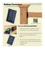
1. Measuring service and installing the AC branch circuit junction box.
WARNING: ONLY USE ELECTRICAL SYSTEM COMPONENTS APPROVED FOR WET LOCATIONS.
2. Attaching the BDM‐250 Micro inverter to the racking.
3. Connecting the BDM‐250 Micro inverter wiring harnesses.
4. Grounding the system.
5. Completing the BDM‐250 Micro inverter installation map and connecting the PV modules.
The finished system should be similar as in the diagram. Detailed installation steps are listed in the following
section.
Step 1 - Install the AC Branch Circuit Junction Box
1. Measure service entrance conductors to confirm AC service at the site. Acceptable ranges are shown
in the table below:
● BDM‐250‐240A & BDM‐250‐208A (North America)
240 Volt AC Single Phase
208 Volt AC Single Phase
L1(red) to L2(black) 211 to 264 Vac
L1(red)
toL2(black) 183 to 229 Vac
L1(red), L2(black) to
106 to 132 Vac
L1(red),
L2(black)
106 to 132 Vac
neutral(blue)
to
neutral(blue)
●BDM‐250‐AU (Australia and New Zealand)
L1(red)to
L2(black)
200 t
o
270 Vac
●BDM‐250‐EU (Europe)
L1(red) to L2(black) Refer to the grid code requirement of local authority
2. Mount the adapter plate at a suitable location on the PV racking system (typically at the end
of a row of modules).
3. Install an appropriate junction box with the adapter plate.

SP-1000
The Solar PaQ
Solar Panel + Inverter + Universal Roof Mount Racking
UPC: 861150002609
Microinverter Instructions
4. Connect the open wire end of the AC interconnect cable into the junction box using an
appropriate gland or strain relief fitting. The AC interconnect cable requires a strain relief
connector with an opening of 3/8 inches in diameter.
Step 2 - Attach the BDM-250 to the Racking
1. Mark the approximate centers of each PV module on the racking system. Evaluate the
location of the micro inverter with respect to the PV module junction box or any other
obstructions.
WARNING: ALLOW A MINIMUM OF .75 INCHES BETWEEN THE TOP OF THE ROOF AND THE BOTTOM OF BDM‐250.
WE ALSO RECOMMEND THAT YOU ALLOW .50 INCHES BETWEEN THE BACK OF THE PV MODULE AND THE TOP OF
BDM‐250. DO NOT MOUNT BDM‐250 IN A LOCATION THAT ALLOWS LONG‐TERM EXPOSURE TO DIRECT SUNLIGHT.
2. If using grounding washers (e.g., WEEB) to ground the micro inverter chassis to the PV
module racking, choose a grounding washer that is approved for the racking manufacturer. Install a
minimum of one grounding washer per micro inverter. Torque the micro inverter fasteners to the
values listed below.
1/4” mounting hardware – 45 inlbs minimum 5/16” mounting hardware – 80 inlbs minimum
3. Mount one micro inverter at each of these locations using hardware recommended by your
module racking vendor. Mounting slots on the micro inverter are 0.33 inches in diameter.
Maximum bolt size is 5/16 inch. The two slots on the micro inverter are 4 inches apart.

SP-1000
The Solar PaQ
Solar Panel + Inverter + Universal Roof Mount Racking
UPC: 861150002609
Microinverter Instructions
Step 3 - Connect the BDM-250 Wiring Harnesses
Each BDM‐250 comes with one 3‐pin bulkhead receptacle (or short pigtail) and one 70‐inch AC wire
harness with multi‐pin connectors. (The DC input wires are approximately six inches long and are
terminated with single pole connectors.) The AC connectors are oppositely sexed, so that multiple
inverters can be connected to form one continuous AC branch circuit.
1. Orient the first BDM‐250 in each branch with its male connector facing the junction box.
The junction box AC interconnect cable has a female connector. The BDM‐250 can be mounted
with either side facing up to accommodate cable routing. Connect the first BDM‐250 to the AC
interconnect cable.
2. Plug the AC connector of the first BDM‐250 into the connector of the next BDM‐250, and so
forth, to form a continuous AC branch circuit. Please check the BDM‐250 rating label for the
maximum allowable number of BDM‐250 on one AC branch circuit. For the chain of the BDM‐250
micro inverters thus formed, one end of the AC cable should be protected by a CAP (refer to the
BDM‐250 accessories). For the other end of the AC cable, it should be connected to an AC junction
box through a tail cable (refer to the BDM‐250 accessories). For BDM‐250‐240A and
BDM‐250‐208A, the L1 wire (red), L2 wire (black) and neutral wire (blue) in the AC cable should be
connected to the corresponding phases of the main grid through the AC junction box. For
BDM‐250‐AU and BDM‐250‐EU, the L1 wire (red) and L2 wire (black) should be connected to the L
and N phases of the main grid respectively at the AC junction box, the green/yellow wire should be
connected to PE.
WARNING: DO NOT EXCEED THE MAXIMUM NUMBER OF BDM-250 IN AN AC BRANCH CIRCUIT, AS DISPLAYED ON
THE UNIT-RATING LABEL. EACH BDM-250 AC BRANCH CIRCUIT MUST BE SOURCED FROM A DEDICATED BRANCH
CIRCUIT PROTECTED BY A 15A MAXIMUM BREAKER.
3. Install a protective end cap on the open AC connector of the last BDM‐250 in the AC branch
circuit.
WARNING: MAKE SURE PROTECTIVE END CAPS HAVE BEEN INSTALLED ON ALL
UNUSED AC CONNECTORS. UNUSED AC BDM‐250 WIRE HARNESS CONNECTORS
ARE LIVE WHEN THE SYSTEM IS ENERGIZED BY THE UTILITY SYSTEM.

SP-1000
The Solar PaQ
Solar Panel + Inverter + Universal Roof Mount Racking
UPC: 861150002609
Microinverter Instructions
Step 4 – Ground the System
Each BDM‐250 comes with a ground clip that can accommodate a 6‐8 AWG conductor. If you are not
using grounding washers to ground the BDM‐250 chassis as described in step2, route a continuous
GEC through each of the BDM‐250 to the NEC approved AC grounding electrode. The racking and module
could be grounded to this conductor using a crimp connection. An alternative method would be to
connect the BDM‐250 to the grounded racking using a grounding washer approved for the racking.
NOTE: The neutral wire (blue) in the AC cable is NOT bonded to earth and earth/ground connection
is not provided via the AC cable through the
micro‐inverter. The earth/ground connector on the enclosure of micro‐inverter
shall be reliably connected to the earth; otherwise there will be a risk of person
shock hazard or fire hazard. The ground conductor size is recommended with at
2
least 4mm and should be larger than live conductor cross section area. Refer

SP-1000
The Solar PaQ
Solar Panel + Inverter + Universal Roof Mount Racking
UPC: 861150002609
Microinverter Instructions
Step 5 – Complete the connection map and connect the PV Modules
BDM‐250 connection Map is a diagrammatic representation of the physical location of each
BDM‐250 in your PV installation. The virtual array in NEP micro inverter gateway BDG‐256 is created
from the map you create.
Complete the connection map
Each BDM‐250 has a removable serial number located on the individual label. Enter the unique
address contained in part of the serial number into a BDG‐256, and correspond it to a number in the
connection map.
Connect the PV Modules
Completely install all BDM‐250 and all system inter‐wiring connections prior to installing the PV
modules.
1. Mount the PV modules above their corresponding BDM‐250. Each BDM‐250 comes with two
oppositely sexed DC connectors.
2. First connect the positive DC wire from the PV module to the positively marked DC connector
(male pin) of the BDM‐250. Then connect the negative DC wire from the PV module to the
negatively marked DC connector (female socket) of the BDM‐250. Repeat for all remaining PV
modules using one BDM‐250 for each module.

SP-1000
The Solar PaQ
Solar Panel + Inverter + Universal Roof Mount Racking
UPC: 861150002609
Microinverter Instructions
5. COMMISSIONING
WARNING: CONNECT BDM‐250 TO THE ELECTRICAL UTILITY GRID ONLY AFTER RECEIVING PRIOR APPROVAL
FROM THE UTILITY COMPANY.
WARNING: BE AWARE THAT ONLY QUALIFIED PERSONNEL CAN CONNECT BDM‐250 TO THE ELECTRICAL
UTILITY GRID.
WARNING: ENSURE THAT ALL AC AND DC WIRING IS CORRECT. ENSURE THAT NONE OF THE AC AND DC
WIRES IS PINCHED OR DAMAGED. ENSURE THAT ALL JUNCTION BOXES ARE PROPERLY CLOSED.
Following these steps to commission the BDM‐250 PV system:
1. Turn on the AC disconnects or circuit breakers on each BDM‐250 AC branch circuit.
2. Turn on the main utility‐grid AC circuit breaker. Your system will start producing power after a
few minutes wait time.
3. The BDM‐250 will start to send performance data over the power lines using power line
communication (PLC) to the BDG‐256. The time required for each BDM‐250 in the system to
communicate to the BDG‐256 will vary with the number of BDM‐250 in the system.

SP-1000
The Solar PaQ
Solar Panel + Inverter + Universal Roof Mount Racking
UPC: 861150002609
Microinverter Instructions
6. OPERATING INSTRUCTIONS
The BDM‐250 is powered on when sufficient DC voltage from the module is applied. The status LED
will start flashing after sufficient DC power is applied as an indication that the BDM‐250 is live.
Status: standby
The LED light is on by 2 second, and off by 2 seconds.
Status: producing power
The LED light is on by 1 second, and off by 1 second.
Error code
Error
Bit‐0 DC over voltage
Bit‐1 DC under voltage
Bit
‐2
hardware error
Bit‐3 Inverter over voltage
Bit
‐4
Frequency over
Bit‐5 Frequency under
Bit
‐6
AC voltage RMS over
Bit‐7 AC voltage RMS under
Bit
‐8
Peak AC voltage over
Bit
‐9
AC current RMS over
Bit‐10 Peak AC current over
Bit‐11 Temperature over
Bit‐12 ADC error
Bit
‐13
GFDI fault indicator
Bit‐14 Relay fault (BDM‐250‐AU/BDM‐250‐EU only)
Bit
‐15
PLC Communication Error

SP-1000
The Solar PaQ
Solar Panel + Inverter + Universal Roof Mount Racking
UPC: 861150002609
Microinverter Instructions
Status: producing power and communicating with BDG-256
The LED light is on by 0.5 second, and off by 0.5 second.
In case of fault, BDM‐250 has multiple protective functions and stops output power. The fault
message may be sent to a connected BDG‐256 gateway through power line communication. The
error message is displayed on the screen of BDG‐256 gateway by a 16‐bit error code.
7. TROUBLESHOOTING AND MAINTENANCE
WARNING: DO NOT ATTEMPT TO REPAIR THE BDM‐250; IT CONTAINS NO
USER‐SERVICEABLE PARTS. IF TROUBLESHOOTING METHODS FAIL, PLEASE RETURN THE BDM‐250 TO YOUR DISTRIBUTOR
FOR MAINTENANCE.
WARNING: NEVER DISCONNECT THE DC WIRE CONNECTORS UNDER LOAD. ENSURE THAT NO CURRENT IS FLOWING IN
THE DC WIRES PRIOR TO DISCONNECTING. AN OPAQUE COVERING MAY BE USED TO COVER THE MODULE PRIOR TO
DISCONNECTING
WARNING: ALWAYS DISCONNECT AC POWER BEFORE DISCONNECTING PV MODULE WIRES FROM BDM‐250. THE AC
CONNECTOR OF THE FIRST BDM‐250 IN A BRANCH CIRCUIT IS SUITABLE AS A DISCONNECTING MEANS ONCE THE AC
BRANCH CIRCUIT BREAKER IN THE LOAD CENTER HAS BEEN OPENED.
WARNING: BDM‐250 IS POWERED BY DC POWER FROM PV MODULES. MAKE SURE YOU DISCONNECT THE DC
CONNECTIONS AND RECONNECT DC POWER TO WATCH FOR THE TWO SECONDS LED ON AND TWO SECONDS LED OFF
AFTER DC IS APPLIED.
LED indication of error
Error report: AC or DC fault
The LED light is on by 4 second, and off by 4 seconds.
Error report: GFDI fault The LED light stays on.

SP-1000
The Solar PaQ
Solar Panel + Inverter + Universal Roof Mount Racking
UPC: 861150002609
Microinverter Instructions
Troubleshooting an inoperable BDM-250
To troubleshoot an inoperable BDM‐250, follow the steps in the order shown:
1. Check the connection to the utility grid. Verify that the utility voltage and frequency are within
allowable ranges shown in the label of BDM‐250.
2. Verify utility power is present at the inverter in question by removing AC, then DC power. Never
disconnect the DC wires while the BDM‐250 is producing power. Re‐connect the DC module
connectors, and then watch for the LED blinks.
3. Check the AC branch circuit interconnection harness between all the BDM‐250. Verify that
each inverter is energized by the utility grid as described in the previous step.
4. Make sure that any AC disconnects are functioning properly and are closed.
5. Verify the PV module DC voltage is within the allowable range shown in the label of BDM‐250.
6. Check the DC connections between the BDM‐250 and the PV module.
7. If the problem persists, please call customer support at NEP.
WARNING: DO NOT ATTEMPT TO REPAIR THE BDM‐250; IT CONTAINS NO
USER‐SERVICEABLE PARTS. IF TROUBLESHOOTING METHODS FAIL, PLEASE RETURN THE BDM‐250 TO YOUR DISTRIBUTOR
FOR MAINTENANCE.
Disconnecting a BDM-250 from the PV Module
To ensure the BDM‐250 is not disconnected from the PV modules under load, adhere to the
following disconnection steps in the order shown:
1. Disconnect the AC by opening the branch circuit breaker.
2. Disconnect the first AC connector in the branch circuit.
3. Cover the module with an opaque cover.
4. Using a DC current probe, verify there is no current flowing in the DC wires between the PV
module and the BDM‐250.
5. Care should be taken when measuring DC currents, most clamp‐on meters must be zeroed
first and tend to drift with time.
6. Disconnect the PV module DC wire connectors from the BDM‐250.
7. Remove the BDM‐250 from the PV array racking.

SP-1000
The Solar PaQ
Solar Panel + Inverter + Universal Roof Mount Racking
UPC: 861150002609
Microinverter Instructions
Installing a replacement BDM-250
1. Attach the replacement BDM‐250 to the PV module racking using hardware recommended by
your module racking vendor. If you are using grounding washers (e.g., WEEB) to ground the chassis
of the BDM‐250, the old grounding washer should be discarded, and a new grounding washer must
be used when installing the replacement BDM‐250. Torque the BDM‐250 fasteners to the values
listed below: 1/4” mounting hardware – 45 in‐lbs minimum
5/16” mounting hardware – 80 in‐lbs minimum.
2. If you are using a grounding electrode conductor to ground the BDM‐250 chassis, attach the
grounding electrode conductor to the BDM‐250 ground clamp.
3. Connect the AC cable of the replacement BDM‐250 and the neighboring BDM‐250 to
complete the branch circuit connections.
4. Complete the connection map and connect the PV Modules.
1) Complete the connection map
2) Each BDM‐250 has a removable serial number located on the individual label. Enter the
unique address contained in part of this serial number into a BDG‐256, and correspond it to a
number in the connection map.
3) Connect the PV Modules
4) Completely install all BDM‐250 and all system inter‐wiring connections prior to installing the
PV modules.
a) Mount the PV modules above their corresponding BDM‐250. Each BDM‐250 comes with two
oppositely sexed DC connectors.
b) First connect the positive DC wire from the PV module to the positively marked DC connector
(male pin) of the BDM‐250. Then connect the negative DC wire from the PV module to the negatively
marked DC connector (female socket) of the BDM‐250. Repeat for all remaining PV modules using
one BDM‐250 for each module.
13

SP-1000
The Solar PaQ
Solar Panel + Inverter + Universal Roof Mount Racking
UPC: 861150002609
Microinverter Instructions
8. SPECIFICATION
MODEL
BDM
-250-240
BDM-250-208A
Max Recommended PV Power (Wp)
285
Max DC Open Circuit Voltage (Vdc)
60
INPUT(DC)
Max DC Input Current (Adc)
12
MPPT Tracking Accuracy >99.5%
MPPT Tracking Range (Vdc)
22‐55
Rated AC Output Power (Wp)
220
Nominal Power Grid Voltage (Vac)
240 / 220
208/220
OUTPUT(AC)
Allowable Power Grid Voltage (Vac) 211‐264/198‐253
186‐2
28/19
8‐253
Allowable Power Grid Frequency (Hz) 59.3‐60.5/45.5‐52.5
THD <2% (at rated power)
Power Factor (cos phi, fixed) >0.99%
SYSTEM
Peak Efficiency 96.3%
95.70
%
CEC Efficiency
95%
EFFICIENCY
Night Time Tare Loss (Wp)
0.17
Over/Under Voltage Protection
Yes
Over/Under Frequency Protection
Yes
Anti‐Islanding Protection
Yes
PROTECTION
Over Current Protection
Yes
/