Page is loading ...

Miller
October
1992
FORM:
OM-154
145
Effective
With
Serial
No.
KC304685
MODEL:
Robotic
Interface
Control
Gas/Current
Sensing
Control
Spool
Support
Assembly
OWNERS
MANUAL
IMPORTANT:
Read
and
understand
the
entire
contents
of
both
this
manual
and
the
power
source
manual
used
with
this
unit,
with
special
emphasis
on
MILLER
ELECTRIC
Mfg.
Co.
A
Miller
Group
Ltd..
Company
the
safety
material
throughout
both
manuals,
before
installing,
operating,
or
maintaining
this
equipment.
This
unit
and
these
instructions
are
for
use
only
P.O.
Box
1079
Appleton,
WI
54912
USA
by
persons
trained
and
experienced
In
the
safe
operation
of
welding
equip-
Tel.
414-734-9821
ment.
Do
not
allow
untrained
persons
to
install,
operate,
or
maintain
this
unit.
Contact
your
distributor
if
you
do
not
fully
understand
these
instructions.
Ref.
ST-157
095
PRINTED
IN
U
S.A

I
I
MILLERS
TRUE
BLUETM
LIMITED
WARRANTY
Effective
January
1,
1992
(Equipment
wlth.a
serial
number
preface
of
XC
or
newer)
This
limited
warranty
supersedes
all
previous
MILLER
warranties
and
is
exclusive
with
rro
other
guarantees
or
warranties
expressed
or
implied
i,t
LIMITED
WARRANTY
Sublect
to
the
terms
and
conditions
below.
MILLER
Electric
MIg
Co
.
dooleton
Wisconsin.
warrants
to
its
original
retail
purchaser
that
new
MILLER
equoment
sold
after
the
effective
date
of
this
limited
warranty
is
freest
de
fects
in
material
and
workmanship
at
the
time
it
is
shipped
by
MILLER
THIS
WAR
RANTY
IS
EXPRESSLY
IN
LIEU
OF
ALL
OTHER
WARRANTIES.
EXPRESS
OR
IMPLIED.
INCLUDING
THE
WARRANTIES
OF
MERCHANTABILITY
AND
FIT
NESS
Within
the
warranty
periods
listed
below.
MILLER
wilt
repair
or
replace
any
war
ranted
pans
or
components
that
tail
due
to
such
defects
in
material
or
workmanship
MILLER
must
be
notilied
in
writing
within
thirty
(30)
days
of
such
detect
or
failure,
at
which
lime
MILLER
will
provide
instructions
on
the
warranty
claim
procedures
to
be
followed.
MILLER
shall
honor
warranty
claims
on
warranted
equipment
listed
below
in
the
event
of
such
a
failure
within
the
warranty
time
periods.
AtI
warranty
time
periods
start
on
the
date
that
the
equipment
was
delivered
to
the
original
retail
purchaser.
and
are
as
follows
5
Years
Psrts
-
3
Years
Labor
Original
main
power
rectifiers
2
3
Years
Parts
and
Labor
TrsnslormerlRectiher
Power
Sources
Plasma
Arc
Cutting
Power
Sources
Semi-Automatic
and
Automatic
Wire
Feeders
Robots
3.
2
Years
Parts
and
Labor
Engine
Driven
Welding
Generators
INOTE.
Engines
are
warranted
separately
by
the
engine
manufacturer
I
d.
t
Year
Parts
and
Labor
Motor
Driven
Guns
Process
Controllers
Water
Coolant
Systems
HF
Units
Grids
Spot
Welders
Load
Banks
SDX
Transformers
Running
Gesr/Trsilers
Field
Options
(NOTE.
Field
options
are
covered
under
True
Blue
tor
the
remaining
warranty
period
of
the
product
they
are
installed
in,
or
for
a
minimum
of
one
year
whichever
is
grealer.I
5.
6
Months
Batteries
6.
90
Days
Parts
and
Labor
*
MIG
GunsiTIG
Torches
Plasma
Cutting
Torches
Remote
Controls
Accessory
Kits
Reolscement
Psr.o
MILLERS
True
BluarM
Limited
Warranty
shall
not
aoolb
to,
Items
lurnished
by
MILLER.
but
manufactured
by
others.
such
as
engines
or
trade
accessories
These
items
are
covered
by
the
manufacturers
warranty,
if
any
2
Consumable
componm3ls:
such
as
contact
tips,
cutting
nozzles,
confactors
and
relays
3,
Eguipmenl
th5t
has
been
modified
by
any
party
other
than
MILLER,
or
equip
ment
that
has
been
improperly
installed,
improperly
operated
or
misused
based
upon
industry
standards,
or
eguioment
which
has
not
had
reasonable
and
necessary
maintenance,
or
equipment
which
hss
been
used
for
operation
outside
of
the
specifications
for
the
eouiomenl
MILLER
PRODUCTS
ARE
INTENDED
FOR
PURCHASE
AND
USE
BY
COMMER
CIAUJINDUSTRIAL
USERS
AND
PERSONS
TRAINED
AND
EXPERIENCED
IN
THE
USE
AND
MAINTENANCE
OF
WELDING
EGUIPMENT
In
the
event
of
a
warranty
claim
covered
by
this
warranty,
the
exclusive
remedies
shall
be.
at
MILLERS
option
tI
repsir,
or
(21
replacement,
or,
where
authorized
in
writing
by
MILLER
in
appropnsfe
cases.
13)
the
reasonable
cost
of
iepair
or
replace
ment
stan
authorized
MtLLER
service
station,
or
~(
payment
of
or
credit
for
the
pur
chase
price
Itess
reasonable
deprecialion
based
upon
actual
usel
upon
return
of
the
goods
at
customers
risk
and
expense.
MILLERS
oplion
of
repair
or
repfacemenf
will
be
F
0.8
Factory
at
Appleton.
Wisconsin.
or
F
0.8.
at
a
MILLER
authorized
ser.
vice
facility
as
determined
by
MILLER
Therefore
no
compensation
or
reimburse
ment
for
transportation
costs
of
any
kind
will
be
allowed,
TO THE
EX7ENT
PERMITTED
BY
LAW,
THE
REMEDIES
PROVtDED
HEREIN
ARE
THE
SOLE
AND
EXCLUSIVE
REMEDIES.
IN
NO
EVENT
SHALL
MILLER
BE
LIABLE
FOR
DIRECt
INDIRECT.
SPECIAL,
INCIDENTAL
OR
CONSEOUENTfAL
DAMAGES
IINCLUDf
NO
LOSS OF
PROFIT),
WHETHER
BASED
ON
CON
TRACt
TORT OR
ANY
OTHER
LEGAL
THEORY
ANY
EXPRESS
WARRANTY
NOT
PROVIDED
HEREIN
AND
ANY
IMPLIED
WAR
RANT?,
GUARANTY
OR
REPRESENTATION
AS
TO
PERFORMANCE,
AND
ANY
REMEDY
FOR
BREACH
OF
CONTRACT
TORT
OR
ANY
OTHER
LEGAL
THEORY
WHICH,
BUT
FOR
THIS
PROVISION.
MIGHT
ARISE
BY
IMPLICATION.
OPERATION
OF
LAW,
CUSTOM
OF
TRADE
OR
COURSE
OF
DEALINO.
IN
CLUDING
ANY
IMPLIED
WARRANTY
OF
MERCHANTABILITY
OR
FITNESS
FOR
PARTICULAR
PURPOSE.
WITH
RESPECT
TO
ANY
AND
ALL
EQUIPMENT
FURNISHED
BY
MILLER
IS
EXCLUDED
AND
DISCLAIMED
BY
MILLER.
Some
slates
in
the
U.S.A.
do
not
allow
limitations
of
how
long
an
implIed
warranty
lasts,
or
the
exclusion
of
incidental,
indirect,
special
or
consequential
damages,
so
the
above
limitation
or
esclusion
may
nol
apply
to
you.
This
warranty
provides
spe
cihc
legal
rights,
and
other
rights
may
be
availasle,
but
may
vary
from
state
to
state.
In
Canada.
legislation
in
some
provinces
provides
to,
certain
additional
warranties
or
remedies
other
Ihan
as
stated
herein,
and
to
the
extent
that
they
may
not
be
waived,
the
limitations
and
exclusions
set
out
above
may
not
apply.
This
Limited
Warranty
provides
specific
legal
rights,
and
other
righls
may
be
available.
buf
may
vary
from
province
to
province.
1.
~~1
5*
RECEIVING-HANDLING
Before
unpacking
equipment,
Check
carton
for
any
damage
that
may
haVB
occurrBd
during
shipment.
File
any
claims
for
loss
or
damage
with
the
delivering
carrier.
Assistance
for
filing
or
settling
claims
may
be
obtained
from
distributor
and/or
equipment
manufacturers
Transportation
Department.
When
requesting
information
about
this
equipment,
always
provide
Model
Designation
and
Serial
or
Style
Number.
Use
the
following
spaces
to
record
Model
Designation
and
Serial
or
Style
Number
of
your
unit.
The
information
is
located
on
the
rating
label
or
nameplate.
Model
_________
Serial
or
Style
No.
Date
of
Purchase
miller
5192

ERRATA
SHEET
Deember
2,
1992
FORM:
OM-154
145
After
this
manual
was
printed,
refinements
in
equipment
design
occurred.
This
sheet
lists
exceptions
to
data
appearing
later
In
this
manual.
AMENDMENT
TO
SECTION
3INSTALLATION
Amend
Figure
3-2.
DVC
DIP
Switch
Setting
Label
S2
Si
1
2
1
2
3
4
5
DELTAWELD
300
ON
ON
ON
DELTAWELD
451
0
ON
ON
DELTAWELD
651
0
ON ON
MAXTRON
300,
400
ON ON
MAXTRON
450
ON
ON
ON
XMT
200/300
ON
ON
ON
ARC
PAK35O
ON ON
ON
SHOPMASTER
300
ON
ON
ON
DIMENSION
400
ON
A
ON
PULSTAR
450
ON
Figure
3-2.
DVC
DIP
Switch
Setting
Label
AMENDMENT
TO
SECTION
8
ELECTRICAL
DIAGRAMS
Amend
Diagram
8-1.
Circuit
Diagram
For
Robotic
Interface
Control
(see
Pages
2
and
3
on
this
Errata
Sheet)
Amend
Diagram
8-3.
Circuit
Diagram
For
Interface
Board
PCi
(see
Pages
4
and
5
on
this
Errata
Sheet)
Amend
Diagram
8-4.
Circuit
Diagram
For
DVC
Board
PC8
(see
Pages
6
and
7
on
this
Errata
Sheet)
Add
Diagram
8-16.
Wiring
Diagram
For
Robotic
Interface
Control
(see
Pages
8
and
9
on
this
Errata
Sheet)
Add
Diagram
8-17.
Wiring
Diagram
For
Gas/Current
Sensing
Control
(see
Page
10
on
this
Errata
Sheet)
Add
Diagram
8-18.
Wiring
Diagram
For
Optional
RCSP-R
Panel
(see
Page
ii
on
this
Errata
Sheet)
AMENDMENT
TO
SECTION
9
PARTS
LIST
Amend
Parts
List
as
follows:
Dia.
Part
Mkgs.
No.
47-
Added
49-7
083147
49-
115092
49-
115093
49-25
..
PC8
..
148320
~First
digit
represents
page
no
digits
following
dash
represent
item
no.
BE
SURE
TO
PROVIDE
MODEL
AND
SERIAL
NUMBER
WHEN
ORDERING
REPLACEMENT
PARTS.
DVC
SWITCH
SETTINGS
O
On
For
Optional
Soft
Start.
Turn
Off
Si
-3.
A
On
For
Optional
Hot
Start.
S.150
864~B
Replaced
With
Description
070
371
.
BLANK,
snap-in
nyl
1.093/1.125
mtg
hole
black
1
Deleted
115
092
.
HOUSING
PLUG
&
SOCKETS,
(qty
chg
added
PLG24)
3
115
093
.
HOUSING
PLUG
&
SOCKETS,
(qty
chg
added
PLG28)
2
152
371
.
CIRCUIT
CARD,
voltage
control
(Eff
w/KC330884)
1
Quantity

Diagram
8-1.
Circuit
Diagram
For
Robotic
Interface
Control
ECO
RCI~
4~
97
9/I
~
/7
~
0-
92
C~DCT
ION
P1.031
I>-!,
2
>~-~
5
>~-5
6
~
I
3
7
S
5
>
Is
________
-7
PCSP-P
C~PCTION
PC
F
(
/0/
95
99
--
U
0
PCI
1~
DVC
BOARO
PCI
-
I
P
PCI/Pt_G8
PC67P1.G6
PC6-2
2C11
RC6-I
>>~-
PCI-Ia
RCI-7>>~-
-~
-(<
PC
1-2
PCI-S
>>~--
I
PCI-a>>
PC
I
-
I
PC4-3
>>~-~
TI
7
PCI-S
_____
__________
iL
PC->>-5
PCI-IS
INTERNAL
PCI-S
>
PC5
Pow~P
sieatv
~
PC
1-9
~
RCI/PtGI7
-
~y
15
7
5C2/PI.GII
-
I
>
PC3/PLGI9
PC
(P1.020
PCG-3
~
PCA/Pt.623
PCG-
10
LISEP
C~PECTI~
RCO/Pt.G22
PCI-12>
PCI
-13
)
/
~
RC2-II>)-~
P1.G33/Pl.G32
A~OWR
ARC
L~TH
IIo.~rAcE
BLRP~A~
VQ.TAGE
51
Ix
9
/9
RC4-2
>?
PCL-I3
>>....
PCS-15
>)
PC4-6
PCI-
2
>>
PCI-IS
PCI-I
RC4-5
RCI-3
PCI-6
X~
PCI-I
)
PCI-S
PCI-i
)~
PCI-2
~j~lZ3<PCs9
PC3-S
PC3-6
/7
95
9
-~
95
>,
-Cc
10
50
PCI-Il
PC
-3
<
PCI-b
-Z~
PCI-2
--
PCI-a
P~~7
>i~
PC2-9>>-~
PCI-I>)7
PCI-I
--~
~-~-
7
-______
L
PLG9,I.~AVE/SE1+
P~0I~o-i
~(
PC2-2
RCA-Il
-
_________________
C-S
~
->~-~ll~_i
__
ANAL~
~
PC3-S
>>~~
REV
.~
REV
~
0~A~IEL
PD
Lv
v
V
V
I
EXTERNAL
/7
P81
PSI
PCI/Pl.OSA
~....
~_
PC3/P1.G2P
PCIP1.G25
F~
Ll-
f::~.j
___________________
~
If
~
-
~
________________
~~<<
PC3-2
C~9CTI~S
I
-
A A
A
A
PC2/P1.GIS
<<
PCIS-7
<<
PCII-I
:~
:~:
:
RC4-4
>>-
~-<<
PC9-3
(P1~
PC3-P
1C5
I
>
RC9-5
MAMJAL
~
~~--(<
P~-
I
PCI
II
>>-
<<RC9-
I
AUTO
6Th-.0_~Z_<<
PCS-2
PC-
10
>~
~<<
SETLP
~
~
PCI-
16
>7
(<
5CR-S
PCI
I
I
ILSP~AOC
XNTEPcACE
ID
10
<
PCI-IS
PCI/PLOI
RC2/Ft.G2
CW
RC3/Pt.G3
<<
PCl-2
PCS/P1.OI
POSTFLOW
I
~9/PtG9
ri!iJ-~-<<
RCI-7
ICWL
99(<RCI-I
PCEFLOW
I
PC
1-9
CR
~1y
<
PCI-3
<<
PC2-
SE
<C
V~xPCIS-I
~
rn
P
II Al
~,
=
~
~
;
~
=
~
~
~
~
-~
-~.
I;.
PC9
I
v.vvv.v.v.v.v.v.v.v.v.vv.v.v.v.v.v.v.v.v.v.vv.v.v.v.v___________
<0
__~_J
..
_~._A.~._J
-.
L.~..d
~
~.
~
_~..)
L.~.J
FILTERPO
I
14
~
4u
,.;~
~
~
I
b
~ER
~ECTI~S
PCS/PLGI
I
PC6/PI.1350
PC7IP1.012
PCI3/DLGI3
OM-154
145
Page
2

CR2
__s~I
~
.7
0
E1~6~
~-r:;:~:::i
~
,0
CR2
~CBI~
~
A
~TOR
CHASSIS
_______
I
I
~
U
CR2
<B
~TOR
-
/
________
________
/0
________________
AAA
PC6
ACIOP
BOARD
:Rcs-sc/9
A-i
P5/PLOIO
-22
~
~
FEEOeACK
o
FEEDBACK
/8
R~-RII4>>
V.
/9
PCR-.i,e>
PC5-5715>
PC5-T/I6
-..SWLRRVII
.7,
85
-
J
Sc
5
LIVE
S
6
.7.72
7
7
7/7/7395
12152627
IT
OO-O
O0O
00
0
0
0
0 0
0
A
B
CD
S
F
C
H
.J
K
L
MN
P
86
85
21
.79
/9
39
82
81
~
9i
92
87
/7
21
0 0 0 0
0
0
0
0
0
O~J
Q
0
0
A
B
C
0
C
F
0
H
J
K~L
MyV.I
P
A~3V~
FOR
RCSP
USE
-7
pci
-5
INT
-22-<M
-~5
tNT
a
9
RCS-Z/22
~-<<
RC5-U/~7
PC5-X/20
I
7
ca
_______
7
39
27
_
I
I
--
-~-<C
7
21
7
2/
77
7
jjj
___(I~j
~T4
_____________
A
)~58J~
)~6O
k
A2
A
AAAAA~AAAA
:~
:~
?~~
U
~
5C2-5
)
Pci-li)
Pci-I
PC4-4
BC4-7~
PCI-B
>)J2_~_
-~
AAAAAAAThA7~
PCI-I
>)~-<<RCI-9
BC
1-4
>>~-<<
PCI
-
3
PCl-IO>~<<RcI-7
OISPLAVBD.
~
!
! !
~ ~
~
RCl-II))~<<RCI-2
G-JK.aUO~GUUUPSK..O.JK._fa,~
PCI-6>).~-<<PCI-,2
v.v.v.v.v.v.v.v.v.v.v.v.v.v.v.v.v.v.v.v.v.v.v_____
___________________
~fflW!1
~
IIPIJTSTO
IA~.JTS1O
0
24V
~I~4
<P
~
<N
I
ISAAC
<H
IA/I
24V
S
GAS
VALVE
~<~WcP
1/
10
.52
5/
~7
85
2
AAAAAAA
0-
U
~RCl-3
PC2
ISQ..ATIOR
PD.
PCI
/PLGI
5
BC2/Pt.GI6
-v-v-v-v
_______
V..1
~
Circuit
Diagram
No.
SD-i
52
896-B
OM-154
145
Page
3

POSTFLOW
~OM
E
OUTPUT
ENABLE
-
cRC4
.241)
(
\/Con
TOUCH
SENSE
INPUT
COMMON
Diagram
8-3.
Circuit
Diagram
For
Interface
Board
PCi
P01)511/GROUND
1(15
FOR
CHIPS
111,112
IICOl1,4ISU
112
S.CO11.IS.ISU
1)3
7~COMI4..I5U
1)4,1)5,1)6
7COI1,IS4ISl)
OM-154
145
Page
4

J~TI~k
J~i!~J~i~!
TU
~
COMMON
~
FORURAD
CR13
JOG
_____________
6
~
CURRENT
~
DETECT
4CJ
~
6
_____
I
6
UELD
I
r~1
I~
~S>STO8Y
CR11
RC5
RC
3
I
9
I
RCS
18
CURRENT
l
RCS
DETECT
RCS
\
I
231
ARC
8C13
FAILURE
L.1
CR9
*r6
~
Circuit
Diagram
No.
SD-146
306-A
OM-154
145
Page
5
~2)CKT
COMMON
C~
Rd~
.1su
~II\DIG
COMM(FUD)
3/
RCS~
DIG
COMII(IN)
18
RCII)DIG
COMM(REUI
~2>DIG
COMM(SUITCH)
RC13
9
4
9
RCS
TOUCH
21
SENSE
BYPRSS
CAPACITORS

8YPASS
C~IT~S
FOR
UI
4~-ISU
12,13.*ISU
A.GP~
132
I4~*I~
7.Gl(P
U3
8.131
3.GPEB
U4
8.UI
3.GPCO
POIIER/GROIAQ
PETS
F~
CHIPS
Al
4.ISU
11.-ISV
82
4.~ISU
11.ISV
83
8.ISV
4-ISU
RI
II5
II.GI~
85
4.132
11.133
I
I.
P..
P.~ISU
iIiT~
I
I
T
L
111
fU~
13
Diagram
8-4.
Circuit
Diagram
For
DVC
Board
PC8
Effective
With
Serial
No.
KC330884
OM-154
145
Page
6
PETS
FOR
CHIPS

0
~l
F~I
~T1~
S~T
ST~T.
TI~l
~F
S1-3
A
O~
F~
~TIlI~.
HOT
ST~T.
3/
r~TER
12
Circuit
Diagram
No.
SD-i
52
374
OM-154
145
Page
7
SUI
TCI4
SET!
IHOS

Diagram
8-16.
Wiring
Diagram
For
Robotic
Interface
Control
L
P2j
#0D)CI-l6LJ
I
902)91
-
i30)cRi
i~
9A(~I-~
-
i3E)#16103)
9C)CRi-g}
~
SR
I
98lP1GI0-&L~
_________
IA)PIG1O-iI
I
i59(~2
I
__________________
3
8)S#i-~G)~
~
t~
~
~)
7-B
7F
PC6
#05/
PIG
iO
~9~5IT4U~
U
z
DI
97
~2T
~
666(PIG25-
is
968
I
PLO
1-6)
TI
85IPIG1A-i
I
3M)
~IIcE
38(~i-AC)
3F(Ii-PR1
3E
)PC8-1)
916)
12)
70)11-Pet)
7(4(88
i-AC)
916
)T2)
7D)P163-3)
7Y
PIG
4.
0)
i7Z)PLG6-i
170)11-0
1~)
7S)PLG1
-5)
288)P162-12)
9fli#4~-~i
IT
3G)PIG31-6)
36
I
FL
i-LOAD)
3-.))SPIlcEL
3C
I
SPt.ICtI
8L6
(13)
7A)881)CO)
79
(F
i-SIDE
7E)SPIICO)
Cs
i
-
I)
I
78(9C2-PI
7V(21-N)
76
I
P1620-S
78
(#168-8)
256(
CR
HA)
230)
PIG
i
0-20)
!iRiP4~R-iIl
9
16
70)
IT-H)
nri~
nt
fl~w
24CiPLG14-3)
39A(P168-i9)
398(PLGIS-8)
i9AiPt.GiO-$(
350(PLG2O-
I)
359
(#10
4-5)
830)PLG8-
i)
SAC
)PLGS-2)
908
(P108-8)
9i8(P1G31
-
920
)PLG8-I0)
938
I
P168-9)
17618102.71
£35
#1620-3
I
430)11-0
901)
45C)Ti-iS
1~
466)91620-4)
,&t~ipI
071
-
ii
958(P1615-1)
i7N(PI_6i5-
ii)
i7H(RiO-cCW)
-IIII:i-IJ
17r~
I~1716M
1~~
~
I
4
42iI~i.~~
I
96
#1624-1
L~!1!41PIG2
13)
37S(PlGil-~j~~~j
i
i
I
~I7URC4F)
960)8(0-OW)
I~
900)91624-3)
986)902-L
804/
P1630
~i1-L)
ri-rn
______________
lA)_Il-Il)
3
P1634-9)
______________
-
350)27-F)
458)17-N
C
D
S
F
6
U
J
8
L
N
N
P
00
85C)PtGi0-
6)
218)PLG15-i2)
_
39C)P16i5-3)
99(803-5)
_
)
P1025-IL
350)802-Mi
300)C82-8
836
I
PIGS-S
639
)P163
-3)
946(9165-li
849)Pt.63i
-1)
90A
(PCi-C)
91A(RC1-E)
929)91631-2)
93A)PCi-O)
i7D)P163i-8)
£39)P(68-6i
430(91631-7)
ARE
iPlG8-7(
450)91031-9)
71.9181
I7Ifl-2~)
279)PIG2-5)
27AiPt.G2i
-2)
00
27C(PIGiO-
17)
8LUi13)
8814)12)
lEt.
)12)
688(12)
496)PIG4-5
PC~
803/
PIG
i
9
Oil
#06/
P1623
I–I..~-l
YEL)T8)
~:
PLG99
iSA
)
99
I-NO.
~64)T#)
1~4-54
A)P62&8)
PC)
80)2/
#1612
+~-4~l
4IAIP9i-r~4I
1
77AIP8I-I~814)
III
SAA)PBi-N.O)
~
59A(PP2-NQ.J~
70)11-F)
SC
1
#01/
#161
696)85-COW)
29A)PLCi4-9)
68A)85-CW
P.
WX~7R
67A)P6-CW
P.
WIPERFi
70A(84-CCW)
7iA)84-CW
~
3i9)Pt6i4-7)
308)P16i413)
32#(P161421
411)51
i7Slil-14)
106)86-COW)
.__~~j.
338(PIGiA-i2)
IC
il-C
IC
iT
i
9-6
i
9-
88(4
19-4
SLUt
iT-P)
84.U)
il-N)
SLkiiI
C)
56(05)-A)
K
K
~~:oT50
1105-6
I1~31T
~iiiA
iT:
806/
#166
PC8
5
6
505/
508)PL624-2)
~
~PI
622
________
39)1K)
X)
ilC
U
I
596(27-01
54A)PI~2~2)
92C)21-L
PCI
/
______________
P168
938)21-Mt
909
)
£58)
IT-N)
438))
1L
78)
il-u)
840)21-U)
830)21-6
PC
Pt.
~25B)
IT-J)_
2
L!Ji
iS
3
II 4
21
9(802-St
606(993-NO.)
~
4IF(P93-O~4(
~1
I
158)82-WIPER)]
275111-8)
~-
6i6(CR2-A~1~
176(21-N)
~rn
8
8
)~1.
P1612)
--~,
~
LiW)PLG1S-9
--~
.
206)P02~K~L~
PC4
802/
#01/
I
_____
#1624
Is
7
6 7 6
9
j;ii~i
~:
91629
8i~i~I~I
L
3T
OM-154
145
Page
8

I
736(810-WIPER
______________
k~~PI~G9-2
~,
51A(PLG8-16(
I~1IC(P(~G9-I
-
~
IOIC(Pt.G.)2-3(
L85021-8
:
(
~IO0A(P1GI0-9(I
75A(R8-WIPER)
Lt~21-E
74A(RiWIPR)
L86A(2T-A)
I.64A(PLG9-4I
76A(R9WIPER
I
I
I
171(52-WIPER
I
~
79A(S2-I4AMJAL
~
82A(S2-~1
IP
L~
I
0
(I)
(I)
0
-
-J
.
U
7)
~
C.)
0
17
8
-cCw
I
RIO
~
66
RIO-CW
(If~fifi
~
C
3:,
1~)
26C(ITN)
27A(IT-P)
38A(PLGIO-l0
328(PLGI-II
-.
24C(21-C)
378(PLGI7-8)
358
(21-F)
668(21-A)
3IO(~GI
-0)
398(21-0)
29A)PLGI
-
I)
liv)
IT-H)
855)21-3)
335(PLGI
-6)
~(PLGI
-4)
)
~
-
*
~
=
~
~i~1
~
I;I:1~J:I:I
~
4A(SI-2)
36)11-B
~
£
.-
~
I
~CC)D4AS
~)
26(801-I)
26A(
IT-N)
~I+
1L1~
I30(RI-TcP)
9C(R3-1~)
IOC(CI-P0S(
25A(
11-4)
2
~0
C-)
n~Jfifi
.7~
fi
-
C-)
A
0)1
-
-,
A
(j)
zu)
I-I
(I)
~
30)11-A
r
___I
56)11-K
:
:
845(21-H
:
638(2T-G
~,
450(11-H)
9~(2T-L
170(21-N)
913(2T-K
43C(l1-L
uu
G)G)
(.1
(.1
1~)
(A11
_______
fl~()
1004(804-H)
C
I03A
~~:i
(
1048(804-C)
IOIC(PLG2O-3)
1045)804-6
OSA(PLGI
2-6)
416(PLGI2-211
1
P
77A(PEGI2-5~
~
~
78A(PLGI2-4)
J
4A)FLI
-LOAD)
6A(FI
~cN1R)
I
iIII~
314(IT-A)
~
ciI_l~_L.l)
~
-I
a
0
ca
0
z
~
p
U)
58A(PLGI
2-3)
4lE)PLGI2-I11
-
1
P
.1I)
i3
4I1(PLG5-3)
?
~
60A(PI..62-2(
j
694)PL6I
-
17)1
P1617-IS
I
-cow
73A
PLO
68A(PLG)-8)
Q~6(P1GI-I2)
70A(PLGI-9)
I.
67A(P1GI-2)
L7IMPLGI-3
hF
87-cow
76
-
9
#7-Ow
3:1
6
\-~-~-
C-)
-4

Diagram
8-17.
Wiring
Diagram
For
Gas/Current
Sensing
Control
99C(PLGI
-7)
L~E~
RELAY
I)
U
I
GI-81
BLACK(CURRE
35A(PLG2-2)
0
~
WHITE(CI.PPE
Bt.Acx(ru)
~Hfti~2-3
PC3
I1B1~Ac~!T!)
t
c~p~FI~J1r.Nn
)58(RC5-l)
z
a
a1
~
.cl
I
_i1
3
SHUNT
I)
U
& U
C
~1
0)
T
RELAY)
GREEN(RC3-R)
GND
STD
14R(PC3-B
C,
rl
U
a
C-I
-I
GREEN(GP~
Sm)
)58(RC3-A)
ii:i~
Lii
I
(((~~
0
190(RC3-E)
RC5
C,
-J
a
z
Ui
Ui
I
(3
-j
a
z
Ui
Ui
a
(3
l~I
(3
-j
a.
3
0
-j -J
Ui
>-
BLACK(PLG2-4)
G2-j~G~I
z
U
C
-I
in
z
Ui
I
3
I
LJ~
a
Ci~
0
BLACK(GSI)
21A(PC3-S)
BLAO(
(CS
I)
PC2/ PLG2
1)21
HI1~I61
2
PC
I
/
PLG
I
I
I,
U
a
I.,
z
Ui UI
a
(2
Wiring
Diagram
No.
SC-i
58
007

Wiring
Diagram
No.
SC-i
58
008
C
I~III1~M
PLG3I
C
PL632
0 C
CC
C
0
f
8381P1G31
-3
64A(PLG~3I
-1
PCI/
PLG7
6
7
6
5
~
3
2
~
N
~
.~
~
IC
I
I43A(PLC2-4)
I30C(~L(~)
I464(PIGS-5)
6
9A(PLG3I-5)
I45AIPLG2-21
~
138A(PIG29-5I
I408IP1628-21
~
II
I378(PLG2-3I
i438(PLGI-51
~
I4IA(PLGSOII
918(PL631-II
29
7A(P1031-6)
142A(P*G29-61
92A(PLG3I
-2)
PC2/PLG8
2
RC3/PLG3
PC5
PLG6/RC6
I
PCI
RC2/PLG2
RCI/PLGI
RC5/PLG5
~
~~2I
RC4
PC3
PSI
I~
PS
IC
Cl
Cl
Cl
C9--
N
1200(30
C
_IJ_J_J
_I
&Q.6.&Q
6~
CC<C<
6
01G01ISC
N
.P,P,flfl
C
N N
C,
-I
&
C
N
C
-I
.4
C
C
(
PC2I
(54
PC2I
jf
308(91
-41
318
(
1-61
32A(PC2-P61
33A
(
1-91
348(51-31
358(51-21
368(91-10)
378191
-41)
408(91
-61
464191
-
I)
47A($II
I
PC6
PLGIO/RCI
ml
m66
___________
PLG
I
2/PLG9
I3~A(PI~I-3)1~~J
2
3
131
Al
PLGS-7
I
_________________
V
~t30C(PIG8-I4V
I308(PI~I2-I
~
I
l(
I
PC2I
1
I
______LI
PC3
LI
__
(
RC4I
A(PL&9I
WIRE
SIZE
SI
e
__
(
52)
All
C:
P3
16
PC2
(~)
L~i~
(PC3
PCI)
WIRE
TYPE
S~ECT
PLG2O/Rca
1368(156)
1358)PIG7-l
Diagram
8-17.
Wiring
Diagram
For
Optional
RCSP-R
Panel

-I

ARC
WELDING
SAFETY
PRECAUTIONS
a
WARNING
ARC
WELDING
can
be
hazardous.
PROTECT
YOURSELF
AND
OTHERS
FROM
POSSIBLE
SERIOUS
INJURY
OR
DEATH.
KEEP
CHILDREN
AWAY.
PACEMAKER
WEARERS
KEEP
AWAY
UNTIL
CONSULTING
YOUR
DOCTOR.
In
welding,
as
in
most
jobs,
exposure
to
certain
hazards
occurs.
Welding
is
sate
when
precautions
are
taken.
The
safety
information
given
below
is
only
a
summary
of
the
more
complete
safety
information
that
will
be
found
in
the
Safety
Standards
listed
on
the
next
page.
Read
and
follow
all
Safety
Standards.
HAVE
ALL
INSTALLATION,
OPERATION,
MAINTENANCE,
AND
REPAIR
WORK
PERFORMED
ONLY
BY
QUALIFIED
PEOPLE.
ELECTRIC
SHOCK
can
kill.
Touching
live
electrical
parts
can
cause
fatal
shocks
or
severe
burns.
The
electrode
and
work
circuit
is
electrically
live
whenever
the
output
is
on.
The
input
power
circuit
and
machine
internal
circuits
are
also
live
when
power
is
on.
in
semiautomatic
or
automatic
wire
welding,
the
wire,
wire
reel,
drive
roll
housing,
and
all
metal
parts
touching
the
welding
wire
are
electrically
live.
Incorrectly
installed
or
improperly
grounded
equipment
is
a
hazard.
1.
Do
not
touch
live
electrical
parts.
2.
Wear
dry,
hole-free
insulating
gloves
and
body
protection.
3.
Insulate
yourself
from
work
and
ground
using
dry
insulating
mats
or
covers.
ARC
RAYS
can
burn
eyes
and
skin;
ARC
RAYS
NOISE
can
damage
hearing.
Arc
rays
from
the
welding
process
produce
intense
heat
and
strong
ultraviolet
rays
that
can
burn
eyes
and
skin.
Noise
from
some
processes
can
damage
hearing.
NOISE
2.
3.
4.
5.
Wear
a
welding
helmet
fitted
with
a
proper
shade
of
filter
(see
ANSI
Z49.
I
listed
in
Safety
Standards)
to
protect
your
face
and
eyes
when
welding
or
watching.
Wear
approved
safety
glasses.
Side
shields
recommended.
Use
protectIve
screens
or
barriers
to
protect
others
from
flash
and
glare;
warn
others
not
to
watch
the
arc.
Wear
protective
clothing
made
from
durable,
flame-resistant
1.
Use
approved
ear
plugs
or
ear
muffs
if
noise
level
is
high.
material
(wool
and
leather)
and
foot
protection.
I,
.
-.-
to
your
health.
FUMES
AND
GASES
can
be
hazardous
Welding
produces
fumes
and
gases.
Breathing
these
fumes
and
gases
can
be
hazardous
to
your
health.
5.
6.
wearing
an
air-supplied
respirator.
Shielding
gases
used
for
Work
in
a
confined
space
only
if
it
is
well
ventilated,
or
while
welding
can
displace
air
causing
injury
or
death.
Be
sure
the
breathing
air
is
safe.
Do
not
weld
in
locatIons
near
degreasing,
cleaning,
or
spraying
1.
Keep
your
head
out
of
the
fumes.
Do
not
breathe
the
fumes.
2.
If
inside,
ventilate
the
area
and/or
use
exhaust
at
the
arc
to
operations.
The
heat
and
rays
of
the
arc
can
react
with
vapors
to
form
highly
toxic
and
irritating
gases.
.
remove
welding
fumes
and
gases.
7.
Do
not
weld
on
coated
metals,
such
as
galvanized,
lead.
or
3.
If
ventilation
is
poor,
use
an
approved
air-supplied
respirator.
cadmium
plated
steel,
unless
the
coating
is
removed
from
the
4.
Read
the
Material
Safety
Data
Sheets
(MSDS5)
and
the
manufacturers
instruction
for
metals,
consumables,
coatings,
weld
area,
the
area
is
well
ventilated,
and
if
necessary,
while
wearing
an
air-supplied
respirator.
The
coatings
and
any
metals
and
cleaners.
containing
these
elements
can
give
off
toxic
fumes
if
welded.
WELDING
can
cause
fire
or
explosion.
5.
Watch
for
fire,
and
keep
a
fire
extinguisher
nearby.
Sparks
and
spatter
fly
off
from
the
welding
arc.
The
flying
sparks
and
hot
metal,
weld
spatter,
hot
workpiece,
and
hot
equipment
can
cause
fires
and
burns.
Accidental
contact
of
electrode
or
welding
wire
to
metal
obiects
can
cause
sparks,
overheating,
or
fire,
6.
7.
8.
Be
aware
that
welding
on
a
ceiling,
floor,
bulkhead,
or
partition
can
cause
fire
on
the
hidden
side.
Do
not
weld
on
closed
containers
such
as
tanks
or
drums.
Connect
work
cable
to
the
work
as
close
to
the
welding
area
as
practical
to
prevent
welding
current
from
traveling
long.
possibly
unknown
paths
and
causing
electric
shock
and
fire
1.
Protect
yourself
and
others
from
flying
sparks
and
hot metal.
hazards.
2.
Do
not
weld
where
flying
sparks
can
strike
flammable
material.
9.
Do
not
use
welder
to
thaw
frozen
pipes.
3.
Remove
all
flammables
within
35
ft
(10.7
m)
of
the
welding
arc.
10.
Remove
stick
electrode
from
holder
or
cut
off
welding
wire
at
If
this
is
not
possible,
tightly
cover
them
with
approved
covers,
contact
tip
when
not
in
use.
4.
Be
alert
that
welding
sparks
and
hot
materials
from
welding
can
11.
Wear
oil-free
protective
garments
Such
as
leather
gloves.
easily
go
through
small
cracks
and
openings
to
adjacent
areas.
heavy
shirt,
cuffiess
trousers,
high
shoes,
and
a
cap.
4
FLYING
SPARKS
AND
HOT
METAL
can
cause
injury,
I
Chipping
and
grinding
cause
flying
metal.
As
welds
~
cool,
they
can
throw
off
slag.
I.
2.
Wear
approved
face
shield
or
safety
goggles.
Side
shields
recommended.
Wear
proper
body
protection
to
protect
skin.
5.
Properly
install
and
ground
this
equipment
according
to
its
Owners
Manual
and
national,
state,
and
local
codes.
6.
When
making
input
connections,
attach
proper
grounding
conductor
first.
7.
Turn
off
all
equipment
when
not
in
use.
8.
Do
not
use
worn,
damaged.
undersized,
or
poorly
spliced
cables.
9.
Do
not
wrap
cables
around
your
body.,
10.
Ground
the
workpiece
to
a
good
electrical
(earth)
ground.
11.
Do
not
touch
electrode
if
in
contact
with
the
work
or
ground.
12.
Use
only
well-maintained
equipment.
Repair
or
replace
damaged
parts
at
once.
13.
Wear
a
safety
harness
f
working
above
floor
level.
14.
Keep
all
panels
and
covers
securely
in
place.
4.
Disconnect
input
power
or
stop
engine
before
installing
or
servicing
this
equipment.
,.I
992

CYLINDERS
can
explode
if
damaged.
Shielding
gas
cylinders
contain
gas
under
high
pressure.
If
damaged.
a
cylinder
can
explode.
Since
gas
cylinders
are
normally
part
of
the
welding
process,
be
sure
to
treat
them
carefully.
Protect
compressed
gas
cylinders
from
excessive
heat,
mechanical
shocks,
and
arcs
2.
Install
and
secure
cylinders
ri
an
upright
position
by
chaining
them
to
a
stationary
support
or
epuipment
cylinder
rack
to
prevent
falling
or
tipoing
A
WARNING
3.
Keep
cylinders
away
from
any
welding
or
other
electrical
circuits.
4.
Never
allow
a
welding
electrode
to
touch
any
cylinder.
5.
Use
only
correct
shielding
gas
cylinders,
regulators.
hoses,
and
fittings
designed
for
the
specific
application~
maintain
them
and
associated
parts
in
good
condition.
6.
Turn
face
away
from
valve
outlet
when
opening
cylinder
valve
7.
Keep
protective
cap
in
place
over
valve
except
when
cylinder
is
ri
use
or
connected
for
use.
8.
Read
and
follow
instructions
on
compressed
gas
cylinders,
associated
equipment,
and
CGA
publication
P-i
listed
in
Safety
Standards.
PRINCIPAL
SAFETY
STANDARDS
Safety
in
Welding
and
Cutting,
ANSI
Standard
Z49.
1,
from
American
Welding
Society.
550
N.W.
LeJeune
Rd.
Miami
FL
33126
Safety
and
Health
Standards,
OSHA
29
CFR
1910.
from
Superinten.
dent
of
Documents,
U.S.
Government
Printing
Office,
Washington,
D.C.
20402.
Recommended
Sate
Practices
for
the
Preparation
for
Welding
and
Cutting
of
Containers
That
Have
Held
Hazardous
Substances.
Amen.
can
Welding
Society
Standard
AWS
F4
1,
from
American
Welding
So
ciety.
550
N.W.
LeJeune
Rd.
Miami,
FL
33126
National
Electrical
Code,
NFPA
Standard
70.
from
National
Fire
Pro
tection
Association,
Batterymarch
Park,
Quincy,
MA
02269.
Safe
Handling
of
Compressed
Gases
in
Cylinders,
CGA
Pamphlet
P-I,
from
Compressed
Gas
Association.
1235
Jefferson
Davis
High
way,
Suite
501,
Arlington,
VA
22202.
Code
for
Safety
in
Welding
and
Cutting,
CSA
Standard
Wi
17.2.
from
Canadian
Standards
Association.
Standards
Sales.
178
Rexdale
Bou
levard,
Rexdale,
Ontario.
Canada
M9W
I
R3.
Safe
Practices
For
Occupation
And
Educational
Eye
And
Face
Prof
ec
tion,
ANSI
Standard
Z87.1,
from
American
National
Standards
Institute,
1430
Broadway,
New
York,
NY
10018.
Cutting
And
Welding
Processes.
NFPA
Standard
518.
from
National
Fire
Protection
Association,
Batterymanch
Park.
Quincy,
MA
02269
ENGINES
can
be
hazardous.
..
.~
ENGINE
EXHAUST
GASES
can
kill.
1.
2.
Use
equipment
outside
in
open,
well-ventilated
areas
It
used
in
a
closed
area,
vent
engine
exhaust
outside
and
Engines
pr
oduce
harmful
exhaust
gases.
away
from
any
building
air
intakes.
ENGINE
FUEL
can
cause
fire
or
1.
Stop
engine
before
checking
or
adding
fuel.
explosion.
2.
Do
not
add
fuel
while
smoking
or
it
unit
is
near
any
sparks
or
open
ftames.
Engine
fuel
is
highly
flammable.
3.
4.
5.
Allow
engine
to
cool
before
fueling.
If
possible,
check
and
add
fuel
to
cold
engine
before
beginning
lob.
Do
not
overfill
tank
allow
room
for
fuel
to
expand.
Do
not
spill
fuel.
If
fuel
is
spilled,
clean
up
before
starting
engine.
MOVING
PARTS
can
cause
injury.
Moving
parts,
such
as
fans,
rotors,
and
belts
can
cut
fingers
and
hands
and
catch
loose
clothing,
3.
4.
Have
only
qualified
people
remove
guards
or
covers
for
maintenance
and
troubleshooting
as
necessary.
To
prevent
accidental
starting
during
servicing,
disconnect
negative
()
battery
cable
from
battery.
1.
Keep
all
doors,
panels,
covers,
and
guards
closed
and
securely
in
place.
2.
Stop
eng
ne
before
installing
or
connecting
unit.
SPARKS
can
cause
BATTERY
GASES
TO
EXPLODE;
BATTERY
ACID
can
burn
eyes
and
skin,
5.
6.
Keep
hands,
hair,
loose
clothing,
and
tools
away
from
moving
parts.
Reinstall
panels
or
guards
and
close
doors
when
servicing
is
finished
and
before
starting
en9ine.
1.
2.
Always
wear
a
face
shield
when
working
on
a
battery.
Stop
engine
before
disconnecting
or
connecting
battery
cables.
3.
Do
not
allow
tools
to
cause
sparks
when
working
on
a
battery.
Batteries
contain
acid
and
generate
explosive
gases.
4.
5.
Do
not
use
welder
to
charge
batteries
or
jump
start
vehicles.
Observe
correct
polarity
(+
and
)
on
batteries.
-~
~
~~~Itii
STEAM
AND
PRESSURIZED
HOT
COOLANT
can
burn
face,
eyes,
and
skin.
under
pressure.
The
coolant
in
the
radiator
can
be
very
hot
and
1.
2.
3.
Oonotremoveradiatorcapwhenengineishot.Allowengine
to
cool.
Wear
gloves
and
put
a
rag
over
cap
area
when
removing
cap.
Allow
pressure
to
escape
before
completely
removing
cap.
~,i
9/92

OM-154
145
10/92
TABLE
OF
CONTENTS
Section
No.
Page
No.
SECTION
1
-
SAFETY
PRECAUTIONS
AND
SIGNAL
WORDS
1.1.
Generai
Information
And
Safety
1
1-2.
Safety
Alert
Symbol
And
Signal
Words
1
SECTION
2
SPECIFICATIONS
2-1.
Description
1
SECTION
3
INSTALLATION
3-1.
Site
Selection
3
3-2.
Equipment
Installation
3
3-3.
Setting
DIP
Switches
On
DVC
Board
PC8
4
3-4.
Burnback
Voltage
And
Wire
Stick
DIP
Switch
On
Interface
Board
4
3-5.
YaskawalMotoman
Robot
Control
Unit
Robot
Interface
Set
Up
5
3-6.
Hitachi
Robot
Control
Unit
Robot
Interface
Set
Up
6
3-7.
Panasonic
Robot
Control
Unit
Robot
Interface
Set
Up
7
3-8.
Automatix
Robot
Control
Unit
Robot
Interface
Set
Up
8
3-9.
GMF
Robot
Control
Unit
Robot
Interface
Set
Up
9
3-10.
ABB
Robot
Control
UnitRobot
Interface
Set
Up
10
3-11.
Kawasaki
Robot
Control
Unit
Robot
Interface
Set
Up
11
3-12.
SMIC
Robot
Control
Unit
Robot
Interface
Set
Up
12
3-13.
Gas/Current
Sensing
Control
Interconnections
13
3-14.
Voltage
Sensing
Connections
14
3-15.
Robot
Interface
Welding
Power
Source
Connections
14
3-16.
Connection
For
Nonpulse
Welding
14
3-17.
Optional
RCSP-R
Set-up
For
Using
Maxtron
300
14
3-18.
Welding
Wire
Installation
15
SECTION
4OPERATOR
CONTROLS
4-1.
Power
Switch
And
Pilot
Light
16
4-2.
Jog
Push
Buttons
16
4-3.
Purge
Push
Button
16
4-4.
Voltmeter
16
4-5.
Wire
Speed
Meter
16
4-6.
Ammeter
17
4-7.
Indicator
Lights
17
4-8.
Preflow
Control
17
4-9.
Postflow
Control
18
4-10.
Burnback
lime
Control
18
4-11.
Burnback
Voltage
Control
18
4-12.
Selector
Switch
18
4-13.
Manual
Controls
18
SECTION
5-
OPTIONAL
RCSP-R
OPERATOR
CONTROLS
5-1.
Wire
Size
Select
Switch
And
Standard
Mode
Indicator
Light
19
5-2.
Wire
Size
Indicator
Lights
19
5-3.
Wire
Type
Select
Switch
19
5-4.
Recommended
Shielding
Gas
Indicator
Lights
20
5-5.
No
Program
Indicator
Light
20
SECTION
6
SEQUENCE
OF
OPERATION
6-1.
Optional
RCSP-R
Gas
Metal
Arc
Welding
(GMAW)
22
6-2.
Shutting
Down
22

Section
No.
Page
No.
SECTION
7-
MAINTENANCE
&
TROUBLESHOOTING
7-1.
Routine
Maintenance
23
7-2.
Overload
Protection
23
7-3.
Reinstallation
Of
Hub
Assembly
23
7-4.
Circuit
Board
Handling
Precautions
24
7-5.
Troubleshooting
25
7-6.
Use
Of
Indicator
Lights
For
Troubleshooting
28
SECTION
8
ELECTRICAL
DIAGRAMS
Diagram
8-1.
Circuit
Diagram
For
Robotic
Interface
Control
30
Diagram
8-2.
Circuit
Diagram
For
Analog
Channel
Board
P04
32
Diagram
8-3.
Circuit
Diagram
For
Interface
Board
PCi
34
Diagram
8-4.
Circuit
Diagram
For
DVC
Board
PC8
36
Diagram
8-5.
Circuit
Diagram
For
Motor
Board
P06
38
Diagram
8-6.
Circuit
Diagram
For
Power
Supply
Board
PC5
39
Diagram
8-7.
Circuit
Diagram
For
Isolation
Board
PC2
40
Diagram
8-8.
Circuit
Diagram
For
Display
Board
PC7
40
Diagram
8-9.
Circuit
Diagram
For
Filter
Board
P09
41
Diagram
8-10.
Circuit
Diagram
For
Gas/Current
Sensing
Control
41
Diagram
8-11.
Circuit
Diagram
For
Optional
RCSP-R
Panel
42
Diagram
8-12.
Circuit
Diagram
For
Feedback
Board
PC1O
42
Diagram
8-13.
Circuit
Diagram
For
Optional
RCSP-R
Offset/Supply
Board
P05
43
Diagram
8-14.
Circuit
Diagram
For
Selector
Board
P06
43
Diagram
8-15.
Circuit
Diagram
For
Optional
RCSP-R
Interface
Board
PCi
44
SECTION
9
PARTS
LIST
Figure
9-1.
Main
Assembly
46
Figure
9-2.
Control
Panel
w/Components
48
Figure
9-3.
Door
Assembly
50
Figure
9-4.
Control
Box,
Gas
Current
52

SECTION
1
SAFETY
PRECAUTIONS
AND
SIGNAL
WORDS
1-1.
GENERAL
INFORMATION
AND
SAFETY
A.
General
Information
presented
in
this
manual
and
on
various
la
bels,
tags,
and
plates
on
the
unit
pertains
to
equipment
design,
installation,
operation,
maintenance,
and
troubleshooting
which
should
be
read,
understood,
and
followed
for
the
safe
and
effective
use
of
this
equipment.
B.
Safety
The
installation,
operation,
maintenance,
and
trouble
shooting
of
arc
welding
equipment
requires
practices
and
procedures
which
ensure
personal
safety
and
the
safety
of
others.
Therefore,
this
equipment
is
to
be
in
stalled,
operated,
and
maintained
only
by
qualified
per
sons
in
accordance
with
this
manual
and
all
safety
pre
cautions
listed
in
the
Arc
Welding
Safety
Precautions.
1.2.
SAFETY
ALERT
SYMBOL
AND
SIGNAL
WORDS
The
following
safety
alert
symbol
and
signal
words
are
used
throughout
this
manual
to
call
attention
to
and
iden
tify
different
levels
of
hazard
and
special
instructions,
4A
This
safety
alert
symbol
is
used
with
the
signal
words
WARNING
and
CAUTION
to
call
atten
tion
to
the
safety
statements.
a
WARNING
statements
identify
procedures
or
practices
which
must
be
followed
to
avoid
seri
ous
personal
injury
or
loss
of
life.
a
CAUTION
statements
identify
procedures
or
practices
which
must
be
followed
to
avoid
minor
personal
injury
or
damage
to
this
equipment.
IMPORTANT
statements
identify
special
instructions
necessary
for
the
most
efficient
operation
of
this
equip
ment.
SECTION
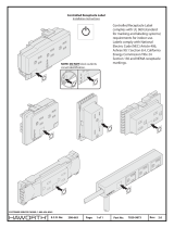
2
SPECIFICATIONS
2-1.
DESCRIPTION
The
robotic
interface
control
is
designed
to
interface
an
Arc
Pak
350,
Deltaweld,
or
Maxtron
300
or
450
welding
power
source
to
a
welding
robot.
This
unit
provides
digi
tal
display
of
weld
volts,wire
feed
speed,
and
amperage.
The
gas/current
sensing
control
contains
the
gas
valve,
current
sensing
reed
relay,
and
shunt.
These
components
function
with
the
robot
system
when
using
the
Gas
Metal
Arc
Welding
(GMAW)
and
Gas
Met
al
Arc
Welding
-
Pulsed
Arc
(GMAW-P)
processes.
The
optional
RCSP-R
panel
is
a
synergic
control
de
signed
to
be
used
with
the
Arc
Pak
350
or
Maxtron
300
or
450
welding
power
sources,
robot
interface,
and
the
ro
bot
system.
The
unit
is
designed
for
Gas
Metal
Arc
Weld
ing
(GMAW)
in
both
nonpulsed
and
pulsed
dc
arc
weld
ing
modes.
The
unit
is
shipped
ready
for
pulsed
welding.
The
panel
is
considered
a
synergic
control
because
welding
parameters
which
determine
arc
power
and
arc
length
are
programmed
for
wire
type
and
size
selections
to
allow
adjustment
at
two
controls
rather
than
individual
controls
for
each
parameter.
If
pulse
welding,
arc
power
parameters
are
wire
feed
speed,
background
amper
age,
peak
amperage,
pulse
frequency,
and
pulse
width;
arc
length
is
a
fine
tuning
of
pulse
frequency.
If
non-pulse
welding,
arc
power
parameters
are
wire
feed
speed,
arc
voltage,
and
inductance;
arc
length
is
a
fine
tuning
of
arc
voltage.
When
used
with
its
associated
equipment,
the
optional
RCSP-R
panel
allows
the
operator
to
set
welding
pa
rameters
for
optimum
welding
conditions
in
a
majority
of
situations
using
various
types
and
sizes
of
welding
wire
and
shielding
gases.
IMPORTANT:
When
using
Maxtron
300
welding
power
source,
it
is
recommended
that
it
be
equipped
with
field
kit
MILLER
Part
No.
146722.
OM.154
145
Page
1

Overall
Dimensions
And
MoUnting
Hole
Locations
Inches
Millimeters
A
21.7/8
556
B
13.3/4
349
i~i
3
76
D
2.1/2
63.5
E
3.1/2
88.9
F
4-1/2
114
G
10-11/16
275
ST
157
095
/
ST080
486-C
Figure
2-1.
Dimensional
Views
in.
mm)
3/8
in.
(10
mm)
25-3/4
in.
(654
mm)
26-1/2
in.
(673
mm)
Opening
For
Receptacle
Kit
Installation
OM-154
145
Page
2
/