Megasat Shipman GPS/Auto Skew User Manual and Installation Instructions
- Category
- Satellite antennas
- Type
- User Manual and Installation Instructions
This manual is also suitable for

Shipman
Shipman GPS/Auto Skew
Benutzerhandbuch und Installationsanleitung
Deutsch
Brillantes FernsehenBrillantes Fernsehen
Page is loading ...
Page is loading ...
Page is loading ...
Page is loading ...
Page is loading ...
Page is loading ...
Page is loading ...
Page is loading ...

Stand: v2.0 April 2013
Brillantes FernsehenBrillantes Fernsehen
User manual and installation instructions
English
Shipman
Shipman GPS/Auto Skew

Contents
1. Introduction
Safety Information ................................................................ 03
Short description ...................................................................03
Delivery ........................................................................................03
System Components ..........................................................04
2. Installation
Installation ................................................................................. 05
Gluing instructions ...............................................................06
Connection ............................................................................... 07
The control unit ......................................................................08
Satellite broadcasting ......................................................... 09
Startup and operation ........................................................10
Setting the LNB skew .......................................................... 11
3. Troubleshooting ................................................................... 12
4. Skew Settings ..........................................................................13
5. Firmware Update ..................................................................14
6. Footprint .....................................................................................16
7. Specications .......................................................................... 17
ENGLISH ENGLISH
02
03
Safety Information
Caution – Improper handling by unqualified personnel can cause serious
damage to this equipment. Unqualified personnel who tamper with this
equipment may be held liable for any resultant damage to the equipment.
Note – Before you begin, carefully read each of the procedures in this ma-
nual. If you have not performed similar operations on comparable equip-
ment, do not attempt to perform these procedures.
Short description
Delivery
The satellite antenna system is the innovative and a technologically advanced satellite
Positioner system. The antenna has a unique combination of cutting-edge components.
Fast satellite search and compatibility with all digital, HD-ready set-top boxes and TV sets
are guaranteed.
Shipman / Shipmas GPS/AS
• Control unit (IDU) incl. powercable
• 1x antenna cable (10 m)
• 1x antenna cable (1 m)
• Installation glue (optional)
• Power supply 230 V (12 V, 5 A) (optional)
• User manual

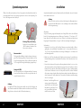
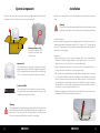
System Components
Antenna unit
The elegant plastic housing will protecting the antenna
against outside weather conditions. Under the housing there
is a 45 cm high-performance antenna. The new technology
of 0-90 ° elevation enables optimal reception across Europe.
Control unit (IDU)
The control unit is used for satellite selection and control. It
is connected between the antenna and the set-top box and
supplied the antenna with electricity.
Open box and remove the control unit, cables and packing material. Lift the antenna
straight up out of the box. Never place the system upside down!
ENGLISH ENGLISH
04
05
Warning:
The Campingman Twin/AutoSkew has an additional Auto Skew function that
adjust the polarization angle of the LNB automatically, and a additional con-
nection for a second set-top box. The control unit must be operated only on
the selected antenna port. Only this is provided for controlling.
Installation
Warning:
Please also note that the antenna height of the vehicle will change accordin-
gly! Please strictly adhere to the various points in the installation instructions!
Basically, we recommend that you leave the installation to make by your dealer or work-
shop!
General information:
Provide a suitable working environment, a garage/warehouse is better than open air. The
ambient temperature for installation is between +5° C and max. +25° C. Work not directly
in the sun. Comply with the safety regulations when handling with chemical products.
Provide the necessary hygiene.
Preparation:
1. Make sure that the roof of your vehicle is sufficiently stable. In case of insufficient or
doubtful roof stability is an approximately 2 mm thick plate with 100 x 100 cm is to be
attached to the outer roof skin. Ask to your vehicle manufacturer.
2. Make sure that all parts are present. You may also need a roof penetration for the con-
necting cable of the antenna. This you get in specialist shops.
3. Place the antenna on the installation area and align it so that the antenna connection
is not facing forward. Make sure that the mounting location is flat and do not interfere
with roof constructions that can interfere with satellite reception. Constructions up to
8 cm in height do not matter, higher constructions should have a respective distance
from the antenna, so that no barrier exists between the antenna and the satellite. The
least distance to an air conditioner should be 30 cm.
4. Clean the mounting surface with a suitable cleaner and a fleece cloth to remove dirt
and impurities. Then draw the antenna feet with a pen.
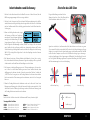
Warning: transport lock
Then remove with the „LOCK“
marked screw on the bottom
of the antenna.

1. Roughen the drawn areas and feet with sandpaper (120 grit) to easily and thoroughly
clean the surface again with Cleaner (WARNING: then no longer touch areas) and let
the clean dry for about 10 minutes.
2. Unless you have a way to run the cable through an existing roof outlet, look for a suita-
ble place (best in the wind shadow behind the antenna) on the roof for the installation
of a roof outlet to avoid the ingress of moisture (eg rain or splash water) in the wellbore.
Make sure that the cables are not curved too much to avoid signal loss and damage
the cable (bending radius max. 5-7 cm).
1. Prepare the glue for mounting.
2. Now take the glue on the underside of the antenna bases in
serpentine lines, so that the glue can harden well to the inside.
3. Now place immediately (within 5 minutes after adhesive application), the antenna on
the marked fields. Press your feet slightly and evenly and fix the antenna so that it
stays in place, eg by an adhesive tape. It must be after pressing for at least 2 mm glue
between antenna and surface. The adhesive is cured max. in 48 hours at +18° C and a
relative humidity of 50%. Should prevail low humidity during the assembly time, spray
after bonding in the vicinity of the antenna always some water in the air.
4. Remove any spilled adhesive immediately with a putty knife or similar and clean the
soiled surfaces with the cleaner and a fleece cloth.
5. For safety, you can attach the antenna bases additionally. Given by drill through the
existing hole in the respective antenna to the roof of your car and fix it with a screw
with locking nut. In order for the freshly bonded feet can not slip, wait with this work
until the adhesive has cured.
6. After the complete assembly and curing of the adhesive, a silicone can be drawn
around the antenna bases.
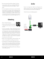
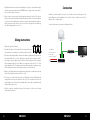
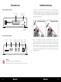
Connection
Gluing instructions
Install the control unit and the set-top box is not inside the vehicle in the region of an
airbag. Maintain a careful installation of the cable in order to avoid short circuits. Pay
attention also to existing cables.
Connect the antenna as shown in the illustration below:
ENGLISH ENGLISH
06
07
Shipman
12~24 V DC 5 A
Antenna
Receiver
( - )
(+)
or with the optional
power supply
230 V AC / 12 V DC 5A
Television
Receiver

Satellite broadcasting
Direct Broadcast Service (DBS) satellites broadcast audio, video and data information
from satellites located 22 miles in space. A receiving station, such as the antenna, should
include a dish and satellite receiver to receive the signals and process them for use by the
consumer audio and video equipment. The system requires a clear view of the satellite to
maximize the signal reception.
Objects such as tall lighthouse, bridges and big ship that block this view will cause a loss
of signal. The signal will be quickly restored once the antenna has a clear line of sight
again. Heavy rain, cloud, snow or ice may also interfere with the signal reception quality.
If the satellite signal is lost due to blockage or severe weather condition, services from
the receiver will be lost (picture will freeze frame and may disappear). When the satellite
signal strength is again high enough, then the receiver will resume providing desired
programming services.
The contron unit
Warning:
Connect the device only at a 7 amp protected line.
The line must be at least 2.5 mm² strong. (never directly to the car battery).
Rear view of the control unit
Front view of the control unit
ENGLISH ENGLISH
08
09
good reception signal bad reception signal
input
power
supply
output
power
supply
connector
antenna
connector
set-top box
connector
service
SD Card
Slot
RS-232SD CARD RECEIVER ANTENNA IN
DC 12~24 V
OUT
Satellite Select
(up/down)
Interrupt
tracking
SATELLITE
SELECT
SLEEP
LCD Display
POWER
OFF
ON

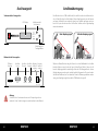
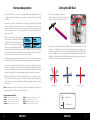
Setting the LNB Skew
Signals in the vertical (red) and horizontal (blue) line have an offset of exactly 90° to each
other. Due to the different position of the satellites, depending on your location, it is pos-
sible that the signals do not meet exactly vertically and horizontally on the LNB. To adjust
this, turn the LNB into the correct position to the transmitted signal. This adjustment to
the LNB is called „skew adjustment“. The following figure shows the optimal setting of the
LNB. More accurate the match, the better of reception.
LNB position
bad reception good reception best reception
Satellite Signal
Startup and operation
1. Turn on the TV and the set-top box. The green LNB LED on the display of the control
box lights up when the satellite receiver is turned on and a supply voltage for the LNB
is available.
2. Turn on the control unit. Then, the indicator of the preset satellites lights red. Shortly
thereafter, the LED starts to flash for about 5 seconds. Only this time you can select
another satellite by press the white key. Each press of the button, the display will con-
tinue to a satellite position. Press it as long until the desired satellite is flashing. Now
the search is started.
3. When a satellite is found, the antenna stop
and carries out a fine-tuning. Then begins
to identify the satellite identification (ID).
This process can be tracked on the display.
After successful identification „LOCKED“ ap-
pears in the display. Should not be identified the satellite of your choice, the antenna
corrected the position. Once the satellite is correct, the display will show it (eg ID:AS1).
After a successful search, the receiver is assured by the antenna.
4. The Shipman has a tracking function, which allows to receive even while driving a per-
manent signal. This is fully automatic and requires no adjustments to the equipment.
5. The antenna is constantly moving in order to detect any changes in the position. If your
vehicle at a fixed location, the movement of the antenna cause irritating noises. There-
fore press the „SLEEP“ button on the control unit to turn off the tracking function of the
antenna. To activate the automatic positioning again, please restart the control unit.
6. When the tracking function is not disabled and there was no movement on the ve-
hicle at least for 10 min., the function is switched off automatically. If the antenna or
the vehicle moves easily (eg walking in the vehicle), the tracking function is activated
automatically.
Note: Changing the satellite is only possible shortly after switching on the power (as
described in point 3) or after successful satellite search.
Preprogrammed satellites:
ENGLISH ENGLISH
10
11
0°
+90°-90°
The following settings are only for the
Shipman (without AutoSkew). An overview of
the skew settings can be found on page 13.
ASTRA 2 Position for Astra 2 to 28,2° East
ASTRA 3 Position for Astra 3 to 23,5° East
ASTRA 1 Position for Astra 1 to 19,2° East
HOTBIRD Position for Hotbird to 13° East
ASTRA 4 Position for Astra 4 (Sirius) to 4,8° East
THOR Position for Thor to 0,8° West
HISPASAT Position for Hispasat to 30° West
TURKSAT Position for Turksat to 42° East

11
Troubleshooting
No Signal
• Objects such as trees, bridges, and large buildings, which are located in the angle of
the satellite will lead to a loss of the signal.
• If the satellite signal is lost through severe weather conditions, the current program
of the receiver is stopped (the image freeze, or disappear). If the weather conditions
allow a good reception again, the TV screen will be restored.
• Make sure that the settings of the set-top box to LNB voltage is switched on. This is
indicated by the green LED on the control unit (LED green = LNB voltage present).
• Only Shipman (without AutoSkew)
If the antenna has not found satellites, check the Skew settings for the satellite
at your location. An overview of the skew settings can be found on page 13. The
basic setting of the LNB is 0°. Should they deviate more than 5°, adjust the degrees
accordingly.
There is dirt on the antenna?
Excessive dirt on the housing may cause reception problems.
Everything is properly connected and turned on?
Your satellite TV receiver might be set up incorrectly or defective. First check the receiver’s
configuration to ensure it is set up for the desired programming. In the case of a faulty re-
ceiver, refer to your selected receiver’s user manual for service and warranty information.
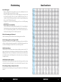
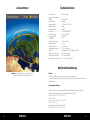
Satellite footprint
Television satellites are located in fixed positions above the Earth’s equator and beam
TV signals down to certain regions of the planet (not worldwide). To receive TV signals
from a satellite, you must be located within that satellite’s unique coverage area. With the
figure on page 10, you can check if you are located in the footprint of the satellite. In the
outlying areas of the footprint there may be interference.
Satellite Frequency Data Changed
If some channels work, while one or more other channels do not, or if the antenna can-
not find the selected satellite, the satellite’s frequency data might have changed.
Error message on the display: „Communication Error“
The antenna is not connected to the control unit. Check the wiring to the antenna.
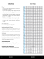
Skew Settings
ENGLISH ENGLISH
12
13

11ENGLISH ENGLISH
14
15
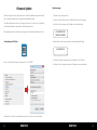
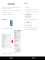
Firmware Update
When the frequency is switched off, on which the antenna idendifiziert the satellite, you
must update the firmware of the control unit.
The current firmware version of the control unit, you can read on the bottom of the
screen in the first 3 seconds after switching on.
Please check our website for the latest firmware version.
Preparing the SD card:
Before you use the SD card, format it to „FAT32“
After you format the SD card, copy the new software on it.
Update process:
1. Turn off the controller.
2. Insert the SD card into the slot on the rear side of the control unit.
3. Turn on the control unit. The following will appear in the display:
4. After the software is copied, the following message appears:
5. Now switch off the control unit and remove the SD card.
6. Turn on the control unit again. The firmware is updated now.
SD CARD DETECTED
WRITING SOFTWARE
LOAD COMPLETE
SD
CARD

Declaration of Conformity
Specications
Note:
Weight and dimensions are not absolutely exact values .
Technical details can be changed at any time (according to manufacturer) without prior
notice.
Declaration of Conformity
This complies with the following directives / standards is confirmed:
Electromagnetic Compatibility Directive 2004/108/EC
EN 55013: 2001 + A1: 2003 + A2: 2006
EN 55020: 2007
EN 61000-3-2:2006 + A1:2009 + A2:2009
EN 61000-3-3:2008
Low Voltage Directive 2006/95/EG
EN 60065: 2002 + A1: 2006 + A11: 2008
Antenna typ ............................................... Off-Set-Dish
Users ...............................................................1
LNB typ ..........................................................Universal LNB
Frequenzy band ..................................... Ku Band
Frequenzy range ....................................10.7 GHz to 12.75 GHz
LNB gain .......................................................33 dBi
Minimum EIRP .......................................... 49 dBW
Polarization ................................................. V/H or RHCP/LHCP
Type of Stabilisation ..............................2-Axis DC Motor
Elevation.......................................................15° to 62°
Azimuth ........................................................360°
Tracking rate ..............................................50° / sec.
Alignment time........................................1 - 2 min.
Temperature range ................................-25° C to +70° C
Power supply .............................................12 V DC @ 5 Amps
Weight ........................................................... 9 kg (Shipman) / 12 kg (Shipman GPS/AS)
Dimensions dish ......................................450 x 300 mm (B/H)
Dimensions antenna ............................700 x 400 mm (Ø/H)
Dimensions control unit ....................245 x 43 x 147 mm (B/H/T)
Footprint
Note: In the outlying areas of the footprint there may be interference.
11ENGLISH ENGLISH
16
17
Page is loading ...
-
 1
1
-
 2
2
-
 3
3
-
 4
4
-
 5
5
-
 6
6
-
 7
7
-
 8
8
-
 9
9
-
 10
10
-
 11
11
-
 12
12
-
 13
13
-
 14
14
-
 15
15
-
 16
16
-
 17
17
-
 18
18
-
 19
19


Megasat Shipman GPS/Auto Skew User Manual and Installation Instructions
- Category
- Satellite antennas
- Type
- User Manual and Installation Instructions
- This manual is also suitable for
Ask a question and I''ll find the answer in the document
Finding information in a document is now easier with AI
in other languages
- Deutsch: Megasat Shipman GPS/Auto Skew
Related papers
-
Megasat Riverman User manual
-
Megasat Shipman User manual
-
-
-
-
-
-
-
-
Other documents
-
Hama 00107229 Owner's manual
-
TechniSat Multytenne Installation guide
-
TechniSat SKYRIDER 65 Twin User manual
-
EOS EMOTEC B6000 Datasheet
-
Maxview MXL012 Operating instructions
-
 Molpir ANT1500 Installation guide
-
 Travel Vision R7 80 User manual
-
-
Kathrein BAS 60 User manual
-
Zanussi Z 21/9 R Operating instructions

