Page is loading ...

2
ENGLISH
Table 1 - Contents of the Kit
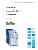
1. DESCRIPTION OF THE KIT
Contents:
3. OPTIONAL MODULE DESCRIPTION
The Modbus-RTU – RS-232 kit is connected directly to the Soft-Starter.
It is tted into the front cover slot for optional plug-in modules.
NOTE!
For more information refer to the SSW-07/SSW-08 Parameter Programming
and to the Serial Communication manual, available on the CD that
comes with the Soft-Starter or at WEG’s web site (www.weg.net).
Table 2 - RS-232 Connection Cables
4. CONNECTION CABLE
The connection cable can be acquired in several models. The Modbus
RTU - RS-232 Kit does not include any cable.
SSW-07/SSW-08 Modbus RTU - RS-232 Kit (Part number: 10194168)
Quantity Description
1 Modbus RTU - RS-232 optional plug-in module
RS-232 Connection Cables
Description Part number
3m RS-232 Connection Cable 10050328
10m RS-232 Connection Cable 10191117
2. SAFETY NOTICES
ATTENTION!
Switch off the Soft-Starter SSW-07/SSW-08 before installing the Modbus
RTU – RS-232 Kit.
The electronic boards have components that are susceptible to
electrostatic discharge. Never touch any of the electrical components
or connectors without following the proper grounding procedures. If it
is necessary to do so, touch the grounded heatsink or use a suitable
grounded wrist strap.

3
ENGLISH
The cable for the Modbus RTU – RS-232 optional plug-in modules uses a DB9
connector. The connector pins are described next:
NOTE!
The RTS pin is not necessary for the RS-232 communication. It will only be
necessary if an external RS-485 gateway is used.
Table 3 - DB9 Connector Pins
5. MODBUS RTU - RS-232 KIT INSTALLATION PROCEDURE
1. Contents of the kit.
2. Take out the optional plug-in cover.
XC41 DB89 Connector
Connector Cable connection Pins of the Description
Pins master / PC
2 2 Rx
3 3 Tx
5 5 COM
7 Not conected Not conected RTS

4
3. Replace the cover with the optional plug-
in module. Make sure that the module is
connected.
4. Insert the DB9 connector to the optional
module and tighten the screws to fix the
connector.
ENGLISH
/