Page is loading ...

R
INSTRUCTION MANUAL
ŕŃŦƋƄƑƑƈƏŐũūŶŶŐŕőŗŪūƝ
ŵƄƇƌƒŃƆƒƑƗƕƒƏŃƖƜƖƗƈƐ
ƉƒƕŃŦƄƕŃŵŒŦŃŶƜƖƗƈƐ

Instruction manual

Thank you for purchasing a Futaba FHSS 2HR 2.4GHz system.
This system is based on the combination of the newly developed 2.4GHz transmitter
and its corresponding receiver. Before using your 2HR 2.4GHz system, read this manual
carefully and use your R/C set safely.
After reading this manual, store it in a safe place.
FHSS 2HR 2.4GHz system
• Frequency channel setting unnecessary: Shifting the channels within the 2.4GHz band
automatically, this system minimizes the interference from other 2.4GHz systems.
• FHSS (Frequency Hopping Spread Spectrum) minimizes interference from other 2.4GHz
systems. This system is not compatible with FASST.
$SSOLFDWLRQ([SRUWDQG0RGL¿FDWLRQ
1. This product may be used for models only. It is not intended for use in any application other than the
control of models for hobby and recreational purposes.
2. Exportation precautions:
(a) When this product is exported from the country of manufacture, its use is to be approved by the laws
governing the country of destination which govern devices that emit radio frequencies. If this product is
then re-exported to other countries, it may be subject to restrictions on such export. Prior approval of the
appropriate government authorities may be required. If you have purchased this product from an exporter
outside your country, and not the authorized Futaba distributor in your country, please contact the seller
immediately to determine if such export regulations have been met.
(b) Use of this product with other than models may be restricted by Export and Trade Control Regulations,
and an application for export approval must be submitted.
3. Modification, adjustment, and replacement of parts: Futaba is not responsible for unauthorized
PRGL¿FDWLRQDGMXVWPHQWDQGUHSODFHPHQWRISDUWVRQ7+5$Q\VXFKFKDQJHVPD\YRLGWKHZDUUDQW\
&KDQJHVRUPRGL¿FDWLRQVQRWH[SUHVVO\DSSURYHGE\WKHSDUW\UHVSRQVLEOHIRUFRPSOLDQFHFRXOGYRLGWKH
user’s authority to operate the equipment.
Compliance Information Statement (for U.S.A.)
This device, trade name Futaba Corporation, model number T2HR-2.4G, complies with part 15 of the FCC
Rules. Operation is subject to the following two conditions:
(1) This device may not cause harmful interference, and
(2) This device must accept any interference received, including interference that may cause undesired
operation.
(3) This device complies with FCC radiation exposure limits set forth for an uncontrolled environment.
This equipment should be installed and operated with minimum distance 20 cm between the radiator and
your body.
The responsible party of this device compliance is:
FUTABA Corporation of America
2681 Wall Triana Hwy Huntsville, AL 35824, U.S.A.
Phone:1-256-461-9399
FAX:1-256-461-1059
Battery Recycling (for U.S.A.)
The RBRC
TM
SEAL on the (easily removable) nickel-cadmium battery contained in Futaba products
indicates that Futaba Corporation of America is voluntarily participating in an industry program to collect
and recycle these batteries at the end of their useful lives, when taken out of service within the United
States. The RBRC
TM
program provides a convenient alternative to placing used nickel-cadmium batteries
into the trash or municipal waste system, which is illegal in some areas.
You may contact your local recycling center for information on where to return the spent battery. Please call
1-800-8-BATTERY for information on Ni-Cd/Ni-MH battery recycling in your area. Futaba Corporation of America's
involvement in this program is part of its commitment to protecting our environment and conserving natural resources.
RBRC
TM
is a trademark of the Rechargeable Battery Recycling Corporation.

Definition of Symbols ............................................................ 6
2.4GHz System Precautions ................................................. 6
Operation Precautions .......................................................... 7
Storage and Disposal Safety Precautions ........................... 8
Other Safety Precautions ...................................................... 9
System Contents .................................................................. 10
Nomenclature / Handling ..................................................... 11
Battery Replacement Method ............................................. 14
Receiver and Servo Connection ......................................... 18
Receiver Antenna Installation ............................................. 18
Assembly Precautions ........................................................ 19
How to Link Transmitter and Receiver ............................... 20
Fail Safe Function (F/S) ....................................................... 21
Transmitter Set-Up Procedures .......................................... 22
Steering Trim ....................................................................... 23
Throttle Trim ........................................................................ 23
Steering Dual Rates (D/R) .................................................. 24
Servo Reversing .................................................................. 24
MC231CR/MC331CR ............................................................ 25
Changing the Neutral Position ........................................... 27
Modifying the Throttle Stick to a Ratchet Type .................. 28
Ratings .................................................................................. 29
Troubleshooting ................................................................... 30
Error Displays ...................................................................... 31
When Requesting Repair ..................................................... 31
Warning: This product contains a chemical known to cause cancer and birth defects (or other
reproductive harm).
• No part of this manual may be reproduced in any form without prior permission.
• The contents of this manual are subject to change without prior notice.
• This manual has been carefully written. Please write to Futaba if you feel that any corrections or clarifications
should be made.
• Futaba is not responsible for the use of this product.

Safety Precautions
Do not cover/hold the built-in antenna part of T2HR-2.4G transmitter by your hand during running. Do
not put any conductive plate/sticker on the antenna part.
Otherwise, the operating range may become shorter.
Do not perform the linking procedure while motor's main wire is connected or the engine is operating
as it may result in serious injury.
While the linking is done, please cycle receiver power and check if the receiver to be linked is really
under the control by the transmitter to be linked.
Always use R202GF 4.8V~7.4V rechargeable battery or regulated output from ESC.
Using dry cell batteries may cause the system to malfunction.
When using an ESC, be sure that the regulated output capacity meets your usage condition.
In order to maintain complete control of your car/boat it is important that it remains visible at all times.
Running behind large objects is not suggested. Doing so may result in the reduction of the quality of
the radio frequency link to the model.
For your safety as well as that of others, please read this manual thoroughly prior to
installation and operation of your digital proportional R/C system.
7KHIROORZLQJGH¿QHVWKHV\PEROVXVHGLQWKLVPDQXDO
Procedures which may lead to a dangerous condition and cause death or
serious injury to the user if not carried out properly.
Procedures which may lead to a dangerous condition or cause death or
serious injury to the user if not carried out properly, or procedures where
the probability of superficial injury or physical damage is high.
Procedures where the possibility of serious injury to the user is small, but
there is a danger of injury, or physical damage, if not carried out properly.
Indicates an operation that prompts a warning (including Caution).
Indicates an operation that must not be performed.
Indicates an operation that always must be performed.

Safety Precautions
When using a Ni-Cd/Ni-MH battery to power your system, always charge and check the battery
voltage prior to operation. Should the battery discharge below the minimum voltage level, control will
be lost.
Prior to operation always perform a range test. Even one abnormality in the R/C system may cause
loss of control.
[Range Test Procedure]
Have a friend hold the model, or place on a stand where the Sticks or prop can not come in contact
with any object. Operate from a distance of about 100 feet. Be sure to check the movement of each
servo to make sure it follows the movement of the steering Stick and throttle Stick. If the servos do
not follow the commands from the transmitter or any type of interference is detected, Do Not operate
the model.
Never operate in the rain or run through puddles.
The transmitter, receiver, batteries and most servos, and speed controls are not waterproof. Contact
with any type of moisture or immersion in water or snow will cause damage along with possible loss
of control. Should any type of moisture enter any component of the system, immediately stop using
the R/C system and return it to our service center for inspection.
Do not operate when visibility is limited.
Should you lose sight of the model, a collision or other dangerous situation may occur.
Do not operate near people or roads.
Do not operate on any pond when boats are present.
Do not operate near high tension power lines or communication broadcasting antennas.
Prior to the operation of any model be sure the area you plan to use is safe.
Be aware of all objects that may be in the path of your model.
Do not operate the model where people or any type of moveable object could stray in the path of your
model.
Control loss due to interference, component failure, loss of sight or low battery voltage could result in
serious injury to yourself and others as well as damage to your model.
Do not operate when you are tired, not feeling well or under the influence of alcohol or drugs.
Your judgment is impaired and could result in a dangerous situation that may cause serious injury to
yourself and others.
(Turning on the power switches)
Always check the throttle Stick on the transmitter to be sure it is at the neutral position.
1. Turn on the transmitter power switch.
2. Turn on the receiver or speed control power switch.
(Turning off the power switches)
Always be sure the engine is not running or the motor is stopped.
1. Turn off the receiver or speed control power switch.
2. Then turn off the transmitter power switch.
If the power switches are turned off in the opposite order the model may unexpectedly run out of con-
trol and cause a very dangerous situation.

Safety Precautions
Make all adjustments to the radio control system with engine not running, or the electric motor
disconnected.
If the engine is running or the motor is connected while adjustments are made, the model may run
out of control.
Remove the main battery source from electric powered models when they are not being used.
Should you accidentally leave the receiver switch on, the model could run out of control.
(Fail safe function)
Before running (cruising), check the fail safe function.
Check Method:
Before starting the engine, check the fail safe function as follows:
1. Turn on the transmitter and receiver power switches.
2. Turn off the transmitter power switch.
3. Check if the fail safe function moves the servos to the preset position when reception fails.
The fail safe function is a safety feature that minimizes set damage by moving the servos to a preset
position when reception fails. However, if set to a dangerous position, it has the opposite effect.
Setting example:
Throttle idle or brake position
Do not touch the engine, motor, speed control or any part of the model that will generate heat while
running.
Touching hot parts will result in serious burns.
When the charger is not in use, disconnect it from the outlet. This will prevent accidents, overheating
and short circuits.
At the end of a day's operation, store the system with Ni-Cd/Ni-MH battery discharged. Be sure to
recharge the system before it is used again.
You should fully discharge your system's batteries periodically to prevent a condition called "memory".
For example, if you only make two runs in a day or you regularly use a small amount of battery's ca-
pacity, the memory effect can reduce the actual capacity even if the battery is charged for the recom-
mended amount of time.
Do not throw a Ni-Cd/Ni-MH battery into a fire. Do not disassemble or attempt to repair a Ni-Cd/Ni-
MH battery pack.
Overheating, damage and acid leakage may lead to burns, loss of eye sight as well as numerous
other types of injuries. The electrolyte in Ni-Cd/Ni-MH batteries is a strong alkali. Should you get even
the smallest amount of the electrolyte in your eyes, Do Not rub. Wash immediately with water, and
seek medical attention at once. The electrolyte can cause blindness. If electrolyte comes in contact
with your skin or clothes, wash with water immediately.
Do not leave the radio system or models within the reach of small children. A small child may acciden-
tally operate the system. This could cause a dangerous situation and injuries. Ni-Cd/Ni-MH batteries
can be very dangerous when mishandled and cause chemical damage.

Safety Precautions
When operating two or more models at the same time, have a third person act as a spotter. They will
be in charge of safety and you should follow their instructions.
Beginners should receive instructions regarding safety and operation from an experienced modeler.
Always use only genuine Futaba transmitter, receivers, servos, and electronic speed controls, along
with other optional parts and components.
Futaba will not be held responsible for damages caused by other than genuine Futaba parts and
components. Use only genuine Futaba parts and components listed in the instruction manual and
catalog.
Do not short circuit the Ni-Cd/Ni-MH battery terminals.
Short circuiting the terminals will lead to sparks and overheating and could cause a fire and burns as
well.
Do not expose plastic parts to fuel, motor spray, waste oil or exhaust.
The fuel, motor spray, waste oil and exhaust will penetrate and damage the plastic.
The electrolyte in Ni-Cd/Ni-MH batteries is a strong alkali. Should you get even the smallest amount of the
electrolyte in your eyes, DO NOT RUB. Wash immediately with water and seek medical attention at once.
The electrolyte can cause blindness. If electrolyte comes in contact with your skin or clothes, wash with
water immediately.
Do not store your R/C system where it will be exposed to the following conditions.
• Extreme heat or coldness
• Exposed to direct sunlight
• Where humidity is high
• Where vibration is prevalent
• Where dust is prevalent
• Where there is steam and condensation
Storing your R/C system under adverse conditions could cause deformation and numerous other
problems with operation.
If the system will not be used for a long period of time, remove the batteries from the model and store
in a cool, dry place.
If the batteries are left in the model, electrolyte may leak and damage the model.
A used Ni-Cd/Ni-MH battery is valuable resource. Insulate the battery terminals and dispose of the battery
by taking it to a battery recycling center.

Before Operation
After opening the container, check the contents for the following items. The contents will
vary with the system purchased.
2HR-2.4GHz System Contents
Transmitter
T2HR-2.4G (x1)
Receiver
R202GF (x1)
Servo
----- S3003 (x2) S3003 (x1) S3003 (x1)
E.S.C.
----- ----- MC231CR (x1) MC331CR (x1)
Switch
SSW-GS (x1) ----- -----
Miscellaneous
Mini Screwdriver
*Servo mounting hardware and servo horns (only w/servo set)
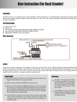
Connectors
"B": Power connector
"2" : Throttle Servo (CH2)
"1" : Steering Servo (CH1)
Link SwitchLED
Servo Horn
Mounting
Flange
NOTE: Futaba FHSS system, T2HR-2.4G transmitter and R202GF receiver, does not
work with current Futaba FASST/FASSTest/T-FHSS systems. Please use T2HR-2.4G
and R202GF in pairs. Futaba FASST/FASSTest/T-FHSS system and FHSS system
are not compatible each other.

Before Operation
Do not cover/hold the built-in antenna part of T2HR-2.4G transmitter by
your hand during running.
Do not put any conductive plate/sticker on the antenna part.
Otherwise, the operating range may become shorter.
As with all radio frequency transmissions,
the strongest area of signal transmission is
from the sides of the antenna(built-in). As
such, the antenna(arrow direction) should
not be pointed directly at the model.
Grip Handle
Throttle Stick
Steering Dual
Rate Dial (D/R)
Antenna (Built-in)
Battery cover
Steering Stick
Power Switch
When slide upward,
the power is turned on.
LED Light
It blinks at Low Battery.
Control the speed
of the model and
movement
forward and
backward.
Adjust the steering sensitivity
across the entire range.
The antenna is inside this part.
Steering Trim
Adjusts the steering in
small increments so
the model will run straight.
Throttle Trim
Adjusts the throttle in small
increments so the
model will not move at neutral.
Turn model to left or
right.

Before Operation

Before Operation
Battery Box
4 AA size dry batteries
Throttle Servo
Reversing
Switch
Steering Servo
Reversing
Switch

Before Operation
Remove the battery cover
from the transmitter by
sliding it to the direction
of the arrow in the figure.
Prepare the new AA size
batteries. Pay very close
attention to the polarity
markings and insert
accordingly.
Slide the battery
cover top onto the
case.
Always be sure you reinsert the
batteries in the correct polarity order.
If the batteries are loaded incor-
rectly, the transmitter may be
damaged.
When the transmitter will not be used
for any short or long period of time,
always remove the batteries.
If the batteries do happen to leak,
clean the battery case and con-
tacts thoroughly. Make sure the
contacts are free of corrosion.
When the LED starts
blinking, change the
batteries immediately.
The low battery alarm
is meant to be a safety
feature only. Do NOT
operate your radio below
low battery. Always shut
your radio off as soon
as possible after the low
battery warning loss of
control.

Before Operation
Do not charge a dry cell battery.
Charging a dry cell battery will
case abnormal heating, etc. and is
dangerous.
Motor connector
Connects to the motor.
(Orange) is positive. (Blue) is negative.
If the motor rotates in the wrong
direction, interchange the connections of
this connector.
Ni-cd/Ni-MH battery connector
Connects to the running Ni-cd/Ni-MH battery.
(Red) is positive. (Black) is negative.
Receiver connector
Connects to the receiver throttle channel.
Miniature screwdriver
Accessory. Use to press the
pushbutton switch.
Checker LED
Power switch
Pushbutton
switch
MC231CR/MC331CR
(Orange)
(Blue)
(Black)
(Red)
Applicable motors (Number of turns is criteria.)
•Use the MC231CR with a motor with 20T or more turns.
•Use the MC331CR with a motor with 13T or more turns.
*If a motor with a number of turns smaller than the above is used, the heat
protector and overcurrent protection circuit may operate. The number of turns
of the motor is only one criteria. Depending on the running conditions, the
protection circuit may operate even if the condition above is satisfied.
Ni-cd/Ni-MH battery 6~7 cells (7.2~8.4V)

Before Operation
When slide upward,
the power is turned on.
ŷƘƕƑƌƑƊŃƒƑŃƗƋƈŃƓƒƚƈƕŃƖƚƌƗƆƋƈƖ ŷƘƕƑƌƑƊŃƒȭŃƗƋƈŃƓƒƚƈƕŃƖƚƌƗƆƋƈƖ

Before Operation

Assembly / Adjustment
As you connect the receiver, servos and other components, do so in accordance
with the "Assembly Precautions".
Connections when a E.S.C. MC231CR or MC331CR are used.
Steering Servo
Throttle Servo
Receiver
Receiver
Power Switch
To Receiver
Battery
Steering Servo
E.S.C.
Power Switch
Connects to Motor
Connects to Battery
Gas Powered Model
Install the R202GF receiver on the car as follows:
Note: The operating range may become shorter, depending on where the
receiver and the antenna are mounted.
Install the antenna in the higher place as shown in the figure.
Keep the antenna as far away from the motor, ESC and other
noise sources as possible.
Put the antenna in the antenna tube to protect it.
Do not cut the antenna.
Do not bend the coaxial cable. Doing so causes damage.
Antenna
tube
Antenna
Coaxial
cable
R202GF

Assembly / Adjustment
Check the receiver, servos, and battery connectors, to be sure they are firmly connected.
If a connector is not fully inserted, vibration may cause the connector to work loose while the model
is operating. This will result in loss of control.
Operate each servo horn over its full stroke and check to see that the linkage does not bind or is not
too loose.
Excessive force applied to the servo horn by binding or poor installation may lead to servo problems
and result in loss of control.
(Electric Cars and Boats)
Isolate the receiver from vibration by attaching to the chassis or mounting plate with thick double
sided tape.
(Gas Powered Cars and Boats)
Isolate the receiver from vibration by wrapping it in foam rubber or similar type cushioning material.
Protect the unit from water damage by placing it in a plastic bag or waterproof radio box.
The receiver contains precision electronic parts. These parts are vulnerable to vibration and shock.
Any contact with moisture (water or condensation) may cause receiver malfunction and loss of con-
trol.
Use the servo horn screw.
When the servo horn comes off, it becomes loss of control.
Keep all devices that emit high frequency noise, such as motors, batteries, and wiring that handles
heavy current loads, at least 1/2 inch away from the receiver and the receiver antenna.
High frequency noise will cause a decrease in operating range and could cause loss of control.
Install electronic speed control heat sinks as well as other components that conduct electricity so they
can not come in contact with aluminum, carbon fiber or other materials that conduct electricity.
If, for example, the speed control came loose while the model was running and touched an aluminum
chassis, a short circuit may occur that would cause irreparable damage to the system as well as loss
of control.
Noise suppression capacitors should be installed on almost all motors.
If the proper capacitors are not installed, high frequency noise will reduce range and cause loss of
control along with various other problems.
Inspect all linkage installations and any point where metal could come in contact with other metal
parts. Make sure these parts do not touch other metal parts under vibration.
Should a linkage or other metal parts come in contact with other metal parts under vibration, the high
frequency noise generated by this contact will cause interference and possible loss of control.
Do Not disassemble any part of this system that is not specified in the instruction manual.
Futaba will not be responsible for any damage due to improper disassembly of any part of the radio
control system.

Assembly / Adjustment
Each transmitter has an individually assigned, unique ID code. In order to start operation,
the receiver must be linked with the ID code of the transmitter with which it is being
paired. Once the link is made, the ID code is stored in the receiver and no further linking
is necessary unless the receiver needs to be used with an other transmitter. (For T/R set,
the link is already done at factory.)
1
Bring the transmitter and the receiver close
to each other, within 0.5 meter.
2
Turn on the transmitter and the receiver.
3
Push and hold the Link Switch of the
receiver.
4
When the link is complete, the LED in the
receiver changes to solid green.
*Please refer the table below for LED status vs receiver's condition.
No signal reception OFF
Receiving signals On
Receiving signals, but ID is unmatched. Blink
Receiving signals, when F/S is set.
It is turns on and a fast blink for the first one
second.
Push and hold the
Link Switch
within 0.5 meter.
h
e
After the linking is done, please cycle receiver power and check that the receiver to be
linked is really under the control of the transmitter.
Do not perform the linking procedure with motor's main wire connected as it may result
in serious injury.

Assembly / Adjustment
For an electric car (E.C.S use),
link the transmitter and the
receiver at neutral position.
For the engine car,
link the transmitter and the
receiver at braking position.
This function moves the throttle
servo to a preset position when the
receiver cannot receive the signal
from the transmitter for some
reason.
When the signal from the
transmitter can be received again,
this function automatically resets.
The throttle position at the link
operation is memorized.
/