
MODEL G0632
16" X 42" VARIABLE SPEED
WOOD LATHE
OWNER'S MANUAL
(For models manufactured since 4/12)
COPYRIGHT © APRIL, 2007 BY GRIZZLY INDUSTRIAL, INC. REVISED MARCH, 2015 (MN)
WARNING: NO PORTION OF THIS MANUAL MAY BE REPRODUCED IN ANY SHAPE
OR FORM WITHOUT THE WRITTEN APPROVAL OF GRIZZLY INDUSTRIAL, INC.
#TS8724 PRINTED IN CHINA

This manual provides critical safety instructions on the proper setup,
operation, maintenance, and service of this machine/tool. Save this
document, refer to it often, and use it to instruct other operators.
Failure to read, understand and follow the instructions in this manual
may result in fire or serious personal injury—including amputation,
electrocution, or death.
The owner of this machine/tool is solely responsible for its safe use.
This responsibility includes but is not limited to proper installation in
a safe environment, personnel training and usage authorization,
proper inspection and maintenance, manual availability and compre-
hension, application of safety devices, cutting/sanding/grinding tool
integrity, and the usage of personal protective equipment.
The manufacturer will not be held liable for injury or property damage
from negligence, improper training, machine modifications or misuse.
Some dust created by power sanding, sawing, grinding, drilling, and
other construction activities contains chemicals known to the State
of California to cause cancer, birth defects or other reproductive
harm. Some examples of these chemicals are:
• Lead from lead-based paints.
• Crystalline silica from bricks, cement and other masonry products.
• Arsenic and chromium from chemically-treated lumber.
Your risk from these exposures varies, depending on how often you
do this type of work. To reduce your exposure to these chemicals:
Work in a well ventilated area, and work with approved safety equip-
ment, such as those dust masks that are specially designed to filter
out microscopic particles.

Table of Contents
INTRODUCTION ............................................... 2
Manual Accuracy ........................................... 2
Contact Info.................................................... 2
Machine Description ...................................... 2
Identification ................................................... 3
Glossary Of Terms ......................................... 5
Machine Data Sheet ...................................... 6
SECTION 1: SAFETY ....................................... 8
Safety Instructions for Machinery .................. 8
Additional Safety for Wood Lathes .............. 10
SECTION 2: POWER SUPPLY ...................... 11
SECTION 3: SETUP ....................................... 13
Needed for Setup ......................................... 13
Unpacking .................................................... 13
Inventory ...................................................... 14
Cleanup ........................................................ 15
Site Considerations ...................................... 16
Mounting to Shop Floor ............................... 17
Assembly ..................................................... 17
Power Connection........................................ 19
Test Run ...................................................... 20
SECTION 4: OPERATIONS ........................... 21
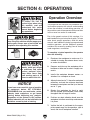
Operation Overview ..................................... 21
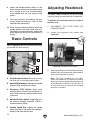
Basic Controls .............................................. 22
Adjusting Headstock .................................... 22
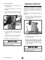
Adjusting Tailstock ....................................... 23
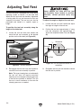
Adjusting Tool Rest ...................................... 24
Installing/Removing Headstock Center ........ 25
Installing/Removing Tailstock Center .......... 26
Headstock Faceplate ................................... 27
Changing Speed Ranges ............................. 28
Indexing ....................................................... 30
Selecting Turning Tools ............................... 31
Spindle Turning ............................................ 32
Faceplate Turning ........................................ 35
Outboard Turning ......................................... 36
Sanding/Finishing ........................................ 36
SECTION 5: ACCESSORIES ......................... 37
SECTION 6: MAINTENANCE ......................... 38
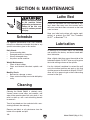
Schedule ...................................................... 38
Cleaning ....................................................... 38
Lathe Bed..................................................... 38
Lubrication ................................................... 38
SECTION 7: SERVICE ................................... 39
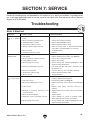
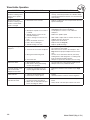
Troubleshooting ........................................... 39
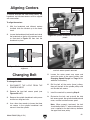
Aligning Centers........................................... 41
Changing Belt .............................................. 41
SECTION 8: WIRING ...................................... 42
Wiring Safety Instructions ............................ 42
Electrical Components ................................. 43
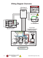
Wiring Diagram Overview ............................ 44
Frequency Inverter Wiring Diagram ............. 45
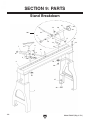
SECTION 9: PARTS ....................................... 46
Stand Breakdown......................................... 46
Headstock Breakdown ................................. 48
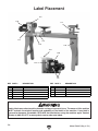
Label Placement .......................................... 50
WARRANTY AND RETURNS ........................ 51

-2-
Model G0632 (Mfg. 4/12+)
INTRODUCTION
We are proud to provide a high-quality owner’s
manual with your new machine!
We
made every effort to be exact with the
instruc-
tions, specifications, drawings, and photographs
in this manual. Sometimes we make mistakes, but
our policy of continuous improvement also means
that
sometimes the machine
you receive is
slightly different than shown in the manual
.
If you find this to be the case, and the difference
between the manual and machine leaves you
confused or unsure about something
,
check our
website for an updated version. W
e post
current
manuals and
manual updates for free
on our web-
site at
www.grizzly.com.
Alternatively, you can call our Technical Support
for help. Before calling, make sure you write down
the
Manufacture Date and Serial Number
from
the machine ID label (see below). This information
is required for us to provide proper tech support,
and it helps us determine if updated documenta-
tion is available for your machine.
Manufacture Date
Serial Number
Manual Accuracy
We stand behind our machines! If you have ques-
tions or need help, contact us with the information
below. Before contacting, make sure you get the
serial number
and manufacture date
from the
machine ID label. This will help us help you faster.
Grizzly Technical Support
1815 W. Battlefield
Springfield, MO 65807
Phone: (570) 546-9663
Email: [email protected]
We want your feedback on this manual. What did
you like about it? Where could it be improved?
Please take a few minutes to give us feedback.
Grizzly Documentation Manager
P.O. Box 2069
Bellingham, WA 98227-2069
Email: [email protected]
Contact Info
Machine Description
The G0632 16" X 42" Wood Lathe is designed
to turn wood stock so the operator can remove
material with a chisel.
The variable speed control allows for spindle
speed adjustment from 100–3200 RPM and the
digital readout provides a precise reading of the
current spindle speed.
The headstock can be positioned anywhere along
the bed for increased flexibility in workpiece
setup.

Model G0632 (Mfg. 4/12+)
-3-
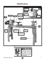
Figure 1. Model G0632 component identification.
Identification
To reduce the risk of
serious injury when using
this machine, read and
understand this entire
manual before beginning
any operations.
Tool Rest
Base
Tool Rest
Lock Handle
Tool Rest
Faceplate
Headstock
Bed
Tool Rest Base
Lock Handle
Quill Lock
Lever
Quill Lock
Handle
Quill
Tailstock
Handwheel
Tailstock
Headstock
Lock Handle
Supporting Leg
Motor
Control
Panel

-4-
Model G0632 (Mfg. 4/12+)
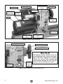
Figure 2. Model G0632 headstock.
Motor
Motor Wiring
Junction Box
Spindle
Handwheel
Frequency Inverter
Spindle Lock
Front Belt Access
Panel
Control Panel
Motor Tensioning
Handle
Motor Mount Cap
Screw
Safety Cover
Headstock
Rotation Lock
Indexing Pin
Hole
NOTICE
The frequency inverter controls on the rear
of the headstock have no effect on the oper-
ation of the lathe. Opening the frequency
inverter will void the lathe warranty and
could seriously damage the lathe. DO NOT
open the case of the frequency inverter.
Figure 3. Model G0632 control panel identification.
Front Belt Access Panel
Spindle RPM Readout
Emergency STOP Button
Variable
Speed Dial
Spindle
Direction
Switch

Model G0632 (Mfg. 4/12+)
-5-
The following is a list of common definitions, terms and phrases used throughout this manual as they relate
to this wood lathe and turning in general. Become familiar with these terms for assembling, adjusting or
operating this machine. Your safety is VERY important to us at Grizzly!
Bed: The long, rail-like metal base to which
the tailstock, tool base, and headstock are
attached.
Chuck: A mechanical device that attaches to the
spindle and holds the workpiece.
Faceplate: The metal disc that threads onto the
headstock spindle.
Faceplate Turning: Turning situation in which
the grain of the turning stock is at right angles
to the lathe bed axis.
Backing Block: A sacrificial piece of wood glued
to the base of the workpiece and screwed to
the faceplate. Often used to prevent mount-
ing marks from appearing on the completed
workpiece.
Headstock: The cast metal box to which the
motor is attached and contains the spindle,
bearings, and electrical components for oper-
ating the lathe.
Index Head: The mechanism that allows the
headstock spindle to be locked at specific
intervals for layout or other auxiliary tasks.
Offset Turning: A turning situation where the cen-
ter of the workpiece is offset at various stages
of the work to produce different shapes.
Outboard Turning: Turning of workpiece with the
headstock situated at the far end of the lathe so
the work done is not over the bed of the lathe.
Roughing Out: Taking stock from square billet to
round blank.
Spindle: This term has two meanings. First, it
refers to the threaded shaft in the headstock
to which the faceplate is attached. Second, it
refers to any work that is spindle-turned.
Spindle-Turning: Work performed where the
grain and length of the workpiece are parallel
to the axis of the bed.
Swing: The capacity of the lathe, measured
by doubling the distance from the bed to the
spindle center.
Tailstock: The metal component at the opposite
end of the bed from the headstock containing a
quill and live or dead centers. It maintains pres-
sure on the spindle-turned workpiece.
Tool Base: The movable metal fixture attached to
the bed upon which the tool rest is fixed. t
Tool Rest: The adjustable metal arm upon which
the tool rests during a turning operation.
Way: One of the metal rails that make up the bed
of the lathe.
Glossary Of Terms

-6-
Model G0632 (Mfg. 4/12+)
The information contained herein is deemed accurate as of 2/20/2018 and represents our most recent product specifications.
Due to our ongoing improvement efforts, this information may not accurately describe items previously purchased.
PAGE 1 OF 3
Model G0632
MACHINE DATA
SHEET
Customer Service #: (570) 546-9663 · To Order Call: (800) 523-4777 · Fax #: (800) 438-5901
MODEL G0632 16" X 42" VARIABLE‐SPEED WOOD LATHE
Product Dimensions:
Weight.............................................................................................................................................................. 386 lbs.
Width (side-to-side) x Depth (front-to-back) x Height........................................................... 77-1/16 x 22-1/16 x 47 in.
Footprint (Length x Width)............................................................................................................... 59-7/8 x 17-3/8 in.
Shipping Dimensions:
Type.......................................................................................................................................................... Wood Crate
Content........................................................................................................................................................... Machine
Weight.............................................................................................................................................................. 394 lbs.
Length x Width x Height....................................................................................................................... 61 x 18 x 22 in.
Must Ship Upright................................................................................................................................................... Yes
Electrical:
Power Requirement........................................................................................................... 220V, Single-Phase, 60 Hz
Prewired Voltage.................................................................................................................................................. 220V
Full-Load Current Rating....................................................................................................................................... 4.7A
Minimum Circuit Size.............................................................................................................................................. 15A
Connection Type....................................................................................................................................... Cord & Plug
Power Cord Included.............................................................................................................................................. Yes
Power Cord Length................................................................................................................................................. 6 ft.
Power Cord Gauge......................................................................................................................................... 16 AWG
Plug Included........................................................................................................................................................... No
Recommended Plug Type..................................................................................................................................... 6-15
Switch Type............................................................................................................................... Sealed Rocker Switch
Inverter (VFD) Type.................................................................................................................................. Delta VFD-S
Inverter (VFD) Size............................................................................................................................................... 1 HP
Motors:
Main
Horsepower............................................................................................................................................. 1.5 HP
Phase.................................................................................................................................................... 3-Phase
Amps........................................................................................................................................................... 4.7A
Speed................................................................................................................................................ 1725 RPM
Type........................................................................................................................................... TEFC Induction
Power Transfer ............................................................................................................................... V-Belt Drive
Bearings..................................................................................................... Shielded & Permanently Lubricated
Main Specifications:
Operation Information
Swing Over Bed......................................................................................................................................... 16 in.
Swing Over Tool Rest Base................................................................................................................ 11-1/2 in.
Distance Between Centers........................................................................................................................ 42 in.
Max. Distance Tool Rest to Spindle Center................................................................................................. 6 in.
No of Spindle Speeds............................................................................................................................ Variable
Spindle Speed Range.............................................................................................................. 100 – 3200 RPM
Floor to Center Height......................................................................................................................... 44-1/2 in.
Headstock Rotation...................................................................................................... 0, 45, 90, 135, 180 deg.
Machine Data Sheet
Machine Data Sheet

Model G0632 (Mfg. 4/12+)
-7-
The information contained herein is deemed accurate as of 2/20/2018 and represents our most recent product specifications.
Due to our ongoing improvement efforts, this information may not accurately describe items previously purchased.
PAGE 2 OF 3
Model G0632
Spindle Information
Spindle Taper............................................................................................................................................ MT#2
Spindle Thread Size..................................................................................................................... 1-1/4" x 8 TPI
Spindle Thread Direction.................................................................................................................. Right Hand
Spindle Bore......................................................................................................................................... 0.445 in.
Type of Included Spindle Center................................................................................................................. Spur
Indexed Spindle Increments................................................................................................................... 10 deg.
No of Indexes................................................................................................................................................. 12
Tool Rest Information
Tool Rest Width................................................................................................................................... 14-1/8 in.
Tool Rest Post Diameter......................................................................................................................... 25 mm
Tool Rest Post Length......................................................................................................................... 2-9/16 in.
Tool Rest Base Height........................................................................................................................... 2-1/8 in.
Tailstock Information
Tailstock Taper.......................................................................................................................................... MT#2
Type of Included Tailstock Center............................................................................................................... Live
Construction
Bed................................................................................................................................ Precision-Ground Steel
Frame................................................................................................................................................... Cast Iron
Stand.................................................................................................................................................... Cast Iron
Base..................................................................................................................................................... Cast Iron
Headstock............................................................................................................................................ Cast Iron
Tailstock............................................................................................................................................... Cast Iron
Paint Type/Finish.................................................................................................................................... Enamel
Other Related Information
Bed Width.................................................................................................................................................... 7 in.
Faceplate Size............................................................................................................................................. 6 in.
Other Specifications:
Country of Origin ................................................................................................................................................ China
Warranty ........................................................................................................................................................... 1 Year
Approximate Assembly & Setup Time ........................................................................................................ 30 Minutes
Serial Number Location .................................................................................................................................. ID Label
ISO 9001 Factory .................................................................................................................................................... No
Certified by a Nationally Recognized Testing Laboratory (NRTL) .......................................................................... No
Features:
Electronic Variable Speed Control
Digital Spindle Speed Indicator
30 deg. Direct Indexing Using One Indexing Hole
10 deg. Indexing Using all Three Indexing Holes
Headstock can be Positioned anywhere along the Bed
Tailstock, Headstock, and Tool Rest Support have Lever Action Cam Locks for Quick Positioning
Belt Drive Offers Two Speed Ranges
Spindle Lock Pin
Outboard Spindle Handle
Forward/Reversing Switch
Emergency Stop Switch
Operates a 3-Phase Motor on Single-Phase Power with Inverter

-8-
Model G0632 (Mfg. 4/12+)
Safety
ELECTRICAL EQUIPMENT INJURY RISKS. You
can be shocked, burned, or killed by touching live
electrical components or improperly grounded
machinery. To reduce this risk, only allow qualified
service personnel to do electrical installation or
repair work, and always disconnect power before
accessing or exposing electrical equipment.
DISCONNECT POWER FIRST.
Always discon-
nect machine from power supply BEFORE making
adjustments, changing tooling, or servicing machine.
This prevents an injury risk from unintended startup
or contact with live electrical components.
EYE PROTECTION. Always wear ANSI-approved
safety glasses or a face shield when operating or
observing machinery to reduce the risk of eye
injury or blindness from flying particles. Everyday
eyeglasses are NOT approved safety glasses.
OWNER’S MANUAL. Read and understand this
owner’s manual BEFORE using machine.
TRAINED OPERATORS ONLY. Untrained oper-
ators have a higher risk of being hurt or killed.
Only allow trained/supervised people to use this
machine. When machine is not being used, dis-
connect power, remove switch keys, or lock-out
machine to prevent unauthorized use—especially
around children. Make your workshop kid proof!
DANGEROUS ENVIRONMENTS. Do not use
machinery in areas that are wet, cluttered, or have
poor lighting. Operating machinery in these areas
greatly increases the risk of accidents and injury.
MENTAL ALERTNESS REQUIRED. Full mental
alertness is required for safe operation of machin-
ery. Never operate under the influence of drugs or
alcohol, when tired, or when distracted.
For Your Own Safety, Read Instruction
Manual Before Operating This Machine
The purpose of safety symbols is to attract your attention to possible hazardous conditions.
This manual uses a series of symbols and signal words intended to convey the level of impor-
tance of the safety messages. The progression of symbols is described below. Remember that
safety messages by themselves do not eliminate danger and are not a substitute for proper
accident prevention measures. Always use common sense and good judgment.
Indicates a potentially hazardous situation which, if not avoided,
MAY result in minor or moderate injury. It may also be used to alert
against unsafe practices.
Indicates a potentially hazardous situation which, if not avoided,
COULD result in death or serious injury.
Indicates an imminently hazardous situation which, if not avoided,
WILL result in death or serious injury.
This symbol is used to alert the user to useful information about
proper operation of the machine.
NOTICE
Safety Instructions for Machinery
SECTION 1: SAFETY

Model G0632 (Mfg. 4/12+)
-9-
WEARING PROPER APPAREL. Do not wear
clothing, apparel or jewelry that can become
entangled in moving parts. Always tie back or
cover long hair. Wear non-slip footwear to reduce
risk of slipping and losing control or accidentally
contacting cutting tool or moving parts.
HAZARDOUS DUST. Dust created by machinery
operations may cause cancer, birth defects, or
long-term respiratory damage. Be aware of dust
hazards associated with each workpiece mate-
rial. Always wear a NIOSH-approved respirator to
reduce your risk.
HEARING PROTECTION. Always wear hear-
ing protection when operating or observing loud
machinery. Extended exposure to this noise
without hearing protection can cause permanent
hearing loss.
REMOVE ADJUSTING TOOLS. Tools left on
machinery can become dangerous projectiles
upon startup. Never leave chuck keys, wrenches,
or any other tools on machine. Always verify
removal before starting!
USE CORRECT TOOL FOR THE JOB. Only use
this tool for its intended purpose—do not force
it or an attachment to do a job for which it was
not designed. Never make unapproved modifica-
tions—modifying tool or using it differently than
intended may result in malfunction or mechanical
failure that can lead to personal injury or death!
AWKWARD POSITIONS. Keep proper footing
and balance at all times when operating machine.
Do not overreach! Avoid awkward hand positions
that make workpiece control difficult or increase
the risk of accidental injury.
CHILDREN & BYSTANDERS. Keep children and
bystanders at a safe distance from the work area.
Stop using machine if they become a distraction.
GUARDS & COVERS. Guards and covers reduce
accidental contact with moving parts or flying
debris. Make sure they are properly installed,
undamaged, and working correctly BEFORE
operating machine.
FORCING MACHINERY. Do not force machine.
It will do the job safer and better at the rate for
which it was designed.
NEVER STAND ON MACHINE. Serious injury
may occur if machine is tipped or if the cutting
tool is unintentionally contacted.
STABLE MACHINE. Unexpected movement dur-
ing operation greatly increases risk of injury or
loss of control. Before starting, verify machine is
stable and mobile base (if used) is locked.
USE RECOMMENDED ACCESSORIES. Consult
this owner’s manual or the manufacturer for rec-
ommended accessories. Using improper acces-
sories will increase the risk of serious injury.
UNATTENDED OPERATION. To reduce the
risk of accidental injury, turn machine OFF and
ensure all moving parts completely stop before
walking away. Never leave machine running
while unattended.
MAINTAIN WITH CARE. Follow all maintenance
instructions and lubrication schedules to keep
machine in good working condition. A machine
that is improperly maintained could malfunction,
leading to serious personal injury or death.
DAMAGED PARTS. Regularly inspect machine
for damaged, loose, or mis-adjusted parts—or
any condition that could affect safe operation.
Immediately repair/replace BEFORE operating
machine. For your own safety, DO NOT operate
machine with damaged parts!
MAINTAIN POWER CORDS. When disconnect-
ing cord-connected machines from power, grab
and pull the plug—NOT the cord. Pulling the cord
may damage the wires inside. Do not handle
cord/plug with wet hands. Avoid cord damage by
keeping it away from heated surfaces, high traffic
areas, harsh chemicals, and wet/damp locations.
EXPERIENCING DIFFICULTIES. If at any time
you experience difficulties performing the intend-
ed operation, stop using the machine! Contact our
Technical Support at (570) 546-9663.

-10-
Model G0632 (Mfg. 4/12+)
Additional Safety for Wood Lathes
KEEPING GUARDS IN PLACE. Make sure all
guards are in place and that the lathe sits on a
flat, stable surface.
EYE/FACE PROTECTION. Airborne wood dust
and debris can be hazardous to the eyes/face
and may cause allergies or long-term respiratory
health problems. Always wear eye protection or a
face shield when operating the lathe.
RESPIRATORY PROTECTION. Always wear a
respirator when using this machine. Wood dust
may cause allergies or long-term respiratory
health problems.
MOUNTING WORKPIECE. Before starting, be
certain the workpiece has been properly imbed-
ded on the headstock and tailstock centers and
that there is adequate clearance for the full rota-
tion.
ADJUSTING TOOL REST. Adjust tool rest to
provide proper support for the turning tool you
will be using. Test tool rest clearance by rotating
workpiece by hand before turning lathe ON.
TURNING SPEED. Select the correct turning
speed for your work, and allow the lathe to gain
full speed before using.
USING SHARP CHISELS. Keep lathe chisels
properly sharpened and held firmly in position
when turning.
OPERATING DAMAGED LATHE. Never oper-
ate the lathe with damaged or worn parts.
WORKPIECE CONDITION. Always inspect the
condition of your workpiece. DO NOT turn pieces
with knots, splits, and other potentially dangerous
conditions. Make sure joints of glued-up pieces
have high quality bonds and won't fly apart during
operation.
ADJUSTMENTS/MAINTENANCE. Make sure
your wood lathe is turned OFF, disconnected from
its power source, and all moving parts have come
to a complete stop before starting any inspection,
adjustment, or maintenance procedure.
STOPPING LATHE. DO NOT stop the lathe by
using your hand against the workpiece. Allow the
lathe to stop on its own.
AVOIDING ENTANGLEMENT. Keep long hair
and loose clothing articles such as sleeves, belts,
and jewelry items away from the lathe spindle.
FACEPLATE TURNING. When faceplate turning,
make sure the faceplate is securely attached to
the workpiece and it is properly attached to the
spindle. When faceplate turning, use lathe chisels
on the downward spinning side of the workpiece
only.
SANDING/POLISHING. Remove the tool rest
when performing sanding or polishing operations
on the rotating spindle.
MATERIAL REMOVAL RATE. Attempting to
remove too much material at once may cause
workpiece to fly out of the lathe.
No list of safety guidelines can be complete.
Every shop environment is different. Always
consider safety first, as it applies to your
individual working conditions. Use this and
other machinery with caution and respect.
Failure to do so could result in serious per-
sonal injury, damage to equipment, or poor
work results.
Like all machinery there is potential danger
when operating this machine. Accidents are
frequently caused by lack of familiarity or
failure to pay attention. Use this machine
with respect and caution to lessen the pos-
sibility of operator injury. If normal safety
precautions are overlooked or ignored, seri-
ous personal injury may occur.

Model G0632 (Mfg. 4/12+)
-11-
Circuit Requirements
SECTION 2: POWER SUPPLY
Availability
Before installing the machine, consider the avail-
ability and proximity of the required power supply
circuit. If an existing circuit does not meet the
requirements for this machine, a new circuit must
be installed. To minimize the risk of electrocution,
fire, or equipment damage, installation work and
electrical wiring must be done by an electrician or
qualified service personnel in accordance with all
applicable codes and standards.
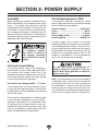
Electrocution, fire, shock,
or equipment damage
may occur if machine is
not properly grounded
and connected to power
supply.
Full-Load Current Rating
The full-load current rating is the amperage a
machine draws at 100% of the rated output power.
On machines with multiple motors, this is the
amperage drawn by the largest motor or sum of all
motors and electrical devices that might operate
at one time during normal operations.
Full-Load Current Rating at 220V .... 4.7 Amps
The full-load current is not the maximum amount
of amps that the machine will draw. If the machine
is overloaded, it will draw additional amps beyond
the full-load rating.
If the machine is overloaded for a sufficient length
of time, damage, overheating, or fire may result—
especially if connected to an undersized circuit.
To reduce the risk of these hazards, avoid over-
loading the machine during operation and make
sure it is connected to a power supply circuit that
meets the specified circuit requirements.
For your own safety and protection of
property, consult an electrician if you are
unsure about wiring practices or electrical
codes in your area.
Note: Circuit requirements in this manual apply to
a dedicated circuit—where only one machine will
be running on the circuit at a time. If machine will
be connected to a shared circuit where multiple
machines may be running at the same time, con-
sult an electrician or qualified service personnel to
ensure circuit is properly sized for safe operation.
A power supply circuit includes all electrical
equipment between the breaker box or fuse panel
in the building and the machine. The power sup-
ply circuit used for this machine must be sized to
safely handle the full-load current drawn from the
machine for an extended period of time. (If this
machine is connected to a circuit protected by
fuses, use a time delay fuse marked D.)
Circuit Requirements for 220V
This machine is prewired to operate on a 220V
power supply circuit that has a verified ground and
meets the following requirements:
Nominal Voltage .............................. 220V/240V
Cycle ..........................................................60 Hz
Phase .................................................... 1-Phase
Power Supply Circuit ......................... 15 Amps
Plug/Receptacle ............................. NEMA 6-15

-12-
Model G0632 (Mfg. 4/12+)
Improper connection of the equipment-grounding
wire can result in a risk of electric shock. The
wire with green insulation (with or without yellow
stripes) is the equipment-grounding wire. If repair
or replacement of the power cord or plug is nec-
essary, do not connect the equipment-grounding
wire to a live (current carrying) terminal.
Check with a qualified electrician or service per-
sonnel if you do not understand these grounding
requirements, or if you are in doubt about whether
the tool is properly grounded. If you ever notice
that a cord or plug is damaged or worn, discon-
nect it from power, and immediately replace it with
a new one.
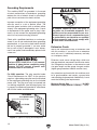
Extension Cords
We do not recommend using an extension cord
with this machine.
If you must use an extension
cord, only use it if absolutely necessary and only
on a temporary basis.
Extension cords cause voltage drop, which can
damage electrical components and shorten motor
life. Voltage drop increases as the extension cord
size gets longer and the gauge size gets smaller
(higher gauge numbers indicate smaller sizes).
Any extension cord used with this machine must
be in good condition and contain a ground wire
and matching plug/receptacle. Additionally, it must
meet the following size requirements:
Minimum Gauge Size ...........................16 AWG
Maximum Length (Shorter is Better).......50 ft.
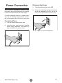
Grounding Requirements
This machine MUST be grounded. In the event
of certain malfunctions or breakdowns, grounding
reduces the risk of electric shock by providing a
path of least resistance for electric current.
Figure 4. Typical 6-15 plug and receptacle.
Grounding Prong
Current Carrying Prongs
6-15 PLUG
GROUNDED
6-15 RECEPTACLE
For 220V operation: The plug specified under
“
Circuit Requirements for 220V” on the previous
page has a grounding prong that must be attached
to the equipment-grounding wire on the included
power cord. The plug must only be inserted into
a matching receptacle (see following figure) that
is properly installed and grounded in accordance
with all local codes and ordinances.
Serious injury could occur if you connect
machine to power before completing setup
process. DO NOT connect to power until
instructed later in this manual.
No adapter should be used with plug. If
plug does not fit available receptacle, or if
machine must be reconnected for use on a
different type of circuit, reconnection must
be performed by an electrician or qualified
service personnel, and it must comply with
all local codes and ordinances.

Model G0632 (Mfg. 4/12+)
-13-
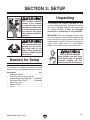
SECTION 3: SETUP
This machine presents
serious injury hazards
to untrained users. Read
through this entire manu-
al to become familiar with
the controls and opera-
tions before starting the
machine!
This machine and its com-
ponents are very heavy.
Get lifting help or use
power lifting equipment
such as a forklift to move
heavy items.
This machine was carefully packaged for safe
transport. When unpacking, separate all enclosed
items from packaging materials and inspect them
for shipping damage.
If items are damaged
,
please
call us immediately at (570) 546-9663.
IMPORTANT:
Save all packaging materials until
you are completely satisfied with the machine and
have resolved any issues between Grizzly or the
shipping agent. You MUST have the original pack-
aging to file a freight claim. It is also extremely
helpful if you need to return your machine later.
Unpacking
SUFFOCATION HAZARD!
Keep children and pets away
from plastic bags or packing
materials shipped with this
machine. Discard immediately.
The following are needed to complete the setup
process, but are not included with your machine.
Description Qty
• Additional People ....................................... 1
• Safety Glasses (for each person) .............. 1
• Cleaner/Degreaser (Page 15) .... As Needed
• Disposable Shop Rags ............... As Needed
• Measuring Tape ......................................... 1
• Wrench 17mm ............................................ 1
• Level ........................................................... 1
Needed for Setup

-14-
Model G0632 (Mfg. 4/12+)
Box Inventory: (Figures 5–7) Qty
A. Lathe Assembly
—Headstock (mounted) ............................. 1
—Tool Rest Base (mounted) ...................... 1
—Tailstock (mounted) ................................ 1
—Face Plate 6" (installed).......................... 1
B. Supporting Legs ......................................... 2
C. Machine Feet .............................................. 4
D. Tool Rest .................................................... 1
E. Spur Center MT#2 ...................................... 1
F. Live Center MT#2 ....................................... 1
G. Hex Wrenches 3, 4, 8mm .....................1 Ea
H. Knockout Tool ............................................ 1
I. Indexing Pin ................................................ 1
J. Hardware (not shown)
—Cap Screws M10-1.5 x 25 ...................... 8
—Lock Washers 10mm .............................. 8
B
C
D
E
F
G
H
Inventory
Figure 6. Model G0632 inventory B.
Figure 7. Model G0632 inventory C–I.
Figure 5. Model G0632 inventory A.
A
I
Inventory
The following is a list of items shipped with your
machine. Before beginning setup, lay these items
out and inventory them.
If any non-proprietary parts are missing (e.g. a
nut or a washer), we will gladly replace them; or
for the sake of expediency, replacements can be
obtained at your local hardware store.
NOTICE
If you cannot find an item on this list, care-
fully check around/inside the machine and
packaging materials. Often, these items get
lost in packaging materials while unpack-
ing or they are pre-installed at the factory.

Model G0632 (Mfg. 4/12+)
-15-
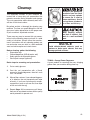
Clean Up
Site Considerations
The unpainted surfaces of your machine are
coated with a heavy-duty rust preventative that
prevents corrosion during shipment and storage.
This rust preventative works extremely well, but it
will take a little time to clean.
Be patient and do a thorough job cleaning your
machine. The time you spend doing this now will
give you a better appreciation for the proper care
of your machine's unpainted surfaces.
There are many ways to remove this rust preven-
tative, but the following steps work well in a wide
variety of situations. Always follow the manufac-
turer’s instructions with any cleaning product you
use and make sure you work in a well-ventilated
area to minimize exposure to toxic fumes.
Before cleaning, gather the following:
• Disposable rags
• Cleaner/degreaser (WD•40 works well)
• Safety glasses & disposable gloves
• Plastic paint scraper (optional)
Basic steps for removing rust preventative:
1.
Put on safety glasses.
2.
Coat the rust preventative with a liberal
amount of cleaner/degreaser, then let it soak
for 5–10 minutes.
3.
Wipe off the surfaces. If your cleaner/degreas-
er is effective, the rust preventative will wipe
off easily. If you have a plastic paint scraper,
scrape off as much as you can first, then wipe
off the rest with the rag.
4.
Repeat Steps 2–3 as necessary until clean,
then coat all unpainted surfaces with a quality
metal protectant to prevent rust.
Gasoline and petroleum
products have low flash
points and can explode
or cause fire if used to
clean machinery. Avo i d
using these products
to clean machinery.
Many cleaning solvents
are toxic if inhaled. Only
work in a well-ventilated
area.
NOTICE
Avoid chlorine-based solvents, such as
acetone or brake parts cleaner, that may
damage painted surfaces.
Cleanup
T23692—Orange Power Degreaser
A great product for removing the waxy shipping
grease from your machine during clean up.
Figure 8. T23692 Orange Power Degreaser.

-16-
Model G0632 (Mfg. 4/12+)
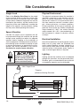
Site Considerations
Figure 9. Minimum working clearances.
220V, Single-Phase
* 17
3
/
8
"
‡ 22
1
/
16
"
Motor
* Footprint
‡ Minimum Working Clearance
* 60"
‡ 77
1
/
4
"
Weight Load
Refer to the
Machine Data Sheet for the weight
of your machine. Make sure that the surface upon
which the machine is placed will bear the weight
of the machine, additional equipment that may be
installed on the machine, and the heaviest work-
piece that will be used. Additionally, consider the
weight of the operator and any dynamic loading
that may occur when operating the machine.
Space Allocation
Consider the largest size of workpiece that will
be processed through this machine and provide
enough space around the machine for adequate
operator material handling or the installation of
auxiliary equipment. With permanent installations,
leave enough space around the machine to open
or remove doors/covers as required by the main-
tenance and service described in this manual.
See below for required space allocation.
Physical Environment
The physical environment where the machine is
operated is important for safe operation and lon-
gevity of machine components. For best results,
operate this machine in a dry environment that is
free from excessive moisture, hazardous chemi-
cals, airborne abrasives, or extreme conditions.
Extreme conditions for this type of machinery are
generally those where the ambient temperature
range exceeds 41°–104°F; the relative humidity
range exceeds 20%–95% (non-condensing); or
the environment is subject to vibration, shocks,
or bumps.
Electrical Installation
Place this machine near an existing power source.
Make sure all power cords are protected from
traffic, material handling, moisture, chemicals, or
other hazards. Make sure to leave enough space
around machine to disconnect power supply or
apply a lockout/tagout device, if required.
Lighting
Lighting around the machine must be adequate
enough that operations can be performed safely.
Shadows, glare, or strobe effects that may distract
or impede the operator must be eliminated.
Children or untrained people
may be seriously injured by
this machine. Only install in an
access restricted location.

Model G0632 (Mfg. 4/12+)
-17-
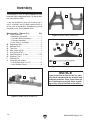
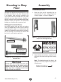
Assembly
To assemble your lathe:
1. Stand the right and left supporting legs up
approximately 47" apart, and get them rea-
sonably aligned, as shown in Figure 11.
The G0632 and its com-
ponents are very heavy.
Get lifting help or use
power lifting equipment
such as a fork lift to move
heavy items.
Figure 11. Stand legs approximately 47" apart to
prepare for mounting the lathe.
2. Using the help of assistants, carefully lift the
lathe onto the stands and align the mounting
holes.
Note: The headstock end of the lathe is the
heaviest and usually requires two people for
lifting that end.
Although not required, we recommend that you
bolt your new lathe to the floor. Because this
is an optional step and floor materials may
vary, machine feet are included with your lathe.
Generally, you can either bolt your machine to
the floor or mount it on the included machine feet.
Whichever option you choose, we recommend
leveling your machine with a precision level.
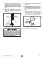
Bolting to Concrete Floors
Lag shield anchors with lag bolts and anchor
studs (see Figure 10) are two popular methods
for anchoring an object to a concrete floor. We
suggest you research the many options and meth-
ods for mounting your machine and choose the
best that fits your specific application.
Mounting to Shop
Floor
Mounting to Shop Floor
NOTICE
Anchor studs are stronger and more per-
manent alternatives to lag shield anchors;
however, they will stick out of the floor,
which may cause a tripping hazard if you
decide to move your machine.
Figure 10. Typical fasteners for mounting to
concrete floors.
Anchor Studs
Lag Shield Anchor
and Lag Screw

-18-
Model G0632 (Mfg. 4/12+)
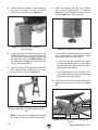
3. Secure the lathe assembly to the supporting
legs with the (8) M10-1.5 x 25 cap screws
and 10mm flat washers (see Figure 12).
Figure 12. Securing lathe assembly to
supporting legs.
4. If you are bolting your lathe to the floor, skip
to Step 7. Otherwise, move the tailstock, tool
rest assembly, and headstock to one end of
the lathe bed (see the OPERATIONS sec-
tion beginning on Page 21 for instructions for
moving these components).
5. Use assistants to lift the light end of the lathe
onto support blocks in preparation for install-
ing the machine feet (see Figure 13).
6. Insert the machine feet into the mounting
holes of the supporting legs, as shown in
Figure 14. Do not tighten the top hex nut yet.
Repeat Steps 5–6 on the other legs.
Figure 14. Machine feet installed.
7. Place a level on the lathe bed and make nec-
essary adjustments so that the bed is level
from side-to-side and front-to-back.
—If you are using the machine feet, adjust
the top and bottom hex nuts on each leg to
level the bed; then tighten the hex nuts to
secure these adjustments.
—If you are bolting your lathe to the floor, use
shims under the legs to level the bed; then
tighten the mounting fasteners.
8. Insert the tool rest into the tool rest base and
tighten the tool rest lock lever (see Figure
15).
Figure 13. Example of supporting one end of
lathe in preparation for installing the machine
feet.
Support Blocks
Note: Use assistants to support and stabilize
the lathe while you install the machine feet.
Figure 15. Tool rest installed on the tool rest
base.
Tool Rest Base
Tool Rest
Tool Rest
Lock Lever
Page is loading ...
Page is loading ...
Page is loading ...
Page is loading ...
Page is loading ...
Page is loading ...
Page is loading ...
Page is loading ...
Page is loading ...
Page is loading ...
Page is loading ...
Page is loading ...
Page is loading ...
Page is loading ...
Page is loading ...
Page is loading ...
Page is loading ...
Page is loading ...
Page is loading ...
Page is loading ...
Page is loading ...
Page is loading ...
Page is loading ...
Page is loading ...
Page is loading ...
Page is loading ...
Page is loading ...
Page is loading ...
Page is loading ...
Page is loading ...
Page is loading ...
Page is loading ...
Page is loading ...
Page is loading ...
Page is loading ...
Page is loading ...
-
 1
1
-
 2
2
-
 3
3
-
 4
4
-
 5
5
-
 6
6
-
 7
7
-
 8
8
-
 9
9
-
 10
10
-
 11
11
-
 12
12
-
 13
13
-
 14
14
-
 15
15
-
 16
16
-
 17
17
-
 18
18
-
 19
19
-
 20
20
-
 21
21
-
 22
22
-
 23
23
-
 24
24
-
 25
25
-
 26
26
-
 27
27
-
 28
28
-
 29
29
-
 30
30
-
 31
31
-
 32
32
-
 33
33
-
 34
34
-
 35
35
-
 36
36
-
 37
37
-
 38
38
-
 39
39
-
 40
40
-
 41
41
-
 42
42
-
 43
43
-
 44
44
-
 45
45
-
 46
46
-
 47
47
-
 48
48
-
 49
49
-
 50
50
-
 51
51
-
 52
52
-
 53
53
-
 54
54
-
 55
55
-
 56
56


Ask a question and I''ll find the answer in the document
Finding information in a document is now easier with AI
Related papers
Other documents
-
Shop fox W1852 Owner's manual
-
Craftsman 351.217160 Owner's manual
-
Rikon Power Tools 70-306 User manual
-
Bellaterra Home BT4801-GY Installation guide
-
-
-
-
-
Harbor Freight Tools 12 in. x 33_3/8 in. 3/4 HP Wood Lathe with Reversible Head User manual
-