ONKYO HT-S5915 Owner's manual

Category
AV receivers
Type
Owner's manual
Front Panel Rear Panel Remote
5.1.2-CHANNEL HOME THEATER SYSTEM
Instruction Manual
HT-S5915
En
Table of contents
Connections
- Connecting Speakers
Playback
Setup
Troubleshooting
Appendix
Supplementary Information
2
Contents
Front Panel Rear Panel Remote
Contents
Connections
Playback
Setup
Table of contents
What’s in the box 4
Additional Function (Firmware Update) 5
Update Information of the rmware 5
Operation of added new functions 5
Firmware Update Procedure 6
Part Names 8
Front Panel 8
Display 10
Rear Panel 11
Remote Controller 13
Speaker/Subwoofer 15
Connections
Connecting speakers 22
Speaker Installation 23
Speaker Connections and "Speaker Setup" Settings 30
Speaker combinations 38
Connecting the TV 39
To ARC TV 40
To Non-ARC TV 41
Connecting Playback Devices 42
Connecting an AV Component
with HDMI Jack Mounted 42
Connecting an Audio Component 44
Connecting an AV Component in a Separate Room
(ZONE B Connection) 45
Connecting a Pre-main Amplier (ZONE B) 45
Connecting Antennas 46
Connecting the Power Cord 47
Playback
AV Component Playback 49
Basic Operations 49
BLUETOOTH
®
Playback 50
Basic Operations 50
Listening To the AM/FM Radio 51
Tuning into a Radio Station 51
Presetting a Radio Station 53
Using RDS 55
ZONE B Playback 56
Playing Back 56
Convenience functions 58
Displaying Your Favorite Video on TV While Playing
Music 58
Adjusting the tone 59
Sleep Timer 60
Listening Mode 61
Selecting a Listening mode 61
3
Front Panel Rear Panel Remote
Contents
Connections
Playback
Setup
Speaker Layouts and Selectable Listening Modes 63
Listening Mode Effects 65
Input Formats and Selectable Listening Modes 69
Setup
Switching the HDMI 4K Signal Format Input and Output
by this Unit 76
Setup Menu 77
Menu list 77
Menu operations 79
1. Input/Output Assign 80
2. Speaker 83
3. Audio Adjust 86
4. Source 88
5. Hardware 89
6. Miscellaneous 92
Quick Menu 93
Menu operations 93
Initial Setup with Auto Start-up Wizard 95
Operations 95
Troubleshooting
When the unit is operating erratically 98
Troubleshooting 99
Appendix
About HDMI 106
General Specications 108
4
Front Panel Rear Panel Remote
Contents
Connections
Playback
Setup
What’s in the box
1. Main unit (HT-R495) (1)
2. Remote controller (RC-970R) (1), Batteries (AAA/R03) (2)
3. Speaker setup microphone (1)
Used during Initial Setup.
4. Indoor FM antenna (1)
5. AM loop antenna (1)
6. Front & Height Speakers (SKF-596) (2)
7. Center speaker (SKC-594) (1)
8. Surround speaker (SKR-594) (2)
9. Powered Subwoofer (SKW-658) (1)
10.
Subwoofer cable (10ft' (3m)) (1)
11.
Speaker cable (10ft' (3m)) (5)
12.
Speaker cable (26ft' (8m)) (2)
13.
Floor Pads (4)
14.
Rubber Stoppers (4)
Place the supplied oor pads in position to receive the feet of the subwoofer
before putting the subwoofer in place. Also stick the rubber stoppers on the
four corners of the base of the center speaker.
Quick Start Guide (1)
* This document is an online instruction manual. It is not included as an
accessory.
Connect speakers with an impedance of 4 Ω to 16 Ω.
The power cord must be connected only after all other connections are
completed.
We will not accept any responsibility for damage arising from the connection
with equipment manufactured by other companies.
Specications and appearance are subject to change without prior notice.
Red
White
Green
Tan
Brown
Gray
Blue


5
Front Panel Rear Panel Remote
Contents
Connections
Playback
Setup
Additional Function (Firmware Update)
This unit is equipped with a function to update the rmware via USB port when the rmware update is announced after purchase. This enables various functions to be
added and operations to be improved.
Depending on the manufacturing timing of the product, the rmware may be switched to the updated one. In such a case, new functions may be added from the start.
For how to conrm the latest rmware contents and the rmware version of your product, see the following section.
Update Information of the rmware
For the latest rmware contents and the rmware version, visit our company’s website. If the rmware version of your product differs from the latest one, it is
recommended to update the rmware.
To conrm the rmware version of your product, press the button on the remote controller, and refer to "6. Miscellaneous" - "Firmware Update" - "Version" ( p92).
Operation of added new functions
If functions are added or changed from contents described in the Instruction Manual, see the following reference.
Supplementary Information
Firmware Update Procedure ( p6)
6
Front Panel Rear Panel Remote
Contents
Connections
Playback
Setup
Firmware Update Procedure
Approx. 30 minutes are required for updating. Existing settings are kept after
updating.
Disclaimer: The program and accompanying online documentation are furnished
to you for use at your own risk.
Our company will not be liable and you will have no remedy for damages for
any claim of any kind whatsoever concerning your use of the program or the
accompanying online documentation, regardless of legal theory, and whether
arising in tort or contract.
In no event will our company be liable to you or any third party for any special,
indirect, incidental, or consequential damages of any kind, including, but not
limited to, compensation, reimbursement or damages on account of the loss of
present or prospective prots, loss of data, or for any other reason whatsoever.
Updating the Firmware via USB
While updating the rmware, do not do the following:
Disconnecting and reconnecting cables, USB storage device, speaker
setup microphone or headphones, or performing operations on the unit
such as turning the power off
Prepare a 128 MB or larger USB storage device. The format of USB storage
devices supports FAT16 or FAT32 le system format.
Media inserted into a USB card reader may not be used for this function.
USB storage devices equipped with the security function are not supported.
USB hubs and USB devices equipped with the hub function are not
supported. Do not connect these devices to the unit.
Delete any data stored on the USB storage device.
If "HDMI CEC" is set to "On", set it to "Off".
Press . Next, select "5. Hardware" - "HDMI" and press ENTER, then
select "HDMI CEC" and select "Off".
* Depending on the USB storage device or its content, long time may be required
for loading, the content may not be loaded correctly, or power may not be supplied
correctly.
* Our company will not be liable whatsoever for any loss or damage of data, or storage
failure arising from the use of the USB storage device. Please note this in advance.
* The descriptions may differ from the actual on-screen displays, however, operations
and functions are the same.
Update
1. Connect the USB storage device to your PC.
2. Download the rmware le from the our company's website to your PC and
unzip.
Firmware les are named as below.
ONKAVR_R.zip
Unzip the le on your PC. The number of unzipped les and folders varies
depending on the model.
3. Copy all unzipped les and folders to the root folder of the USB storage
device.
Make sure to copy the unzipped les.
4. Connect the USB storage device to the POWER OUT port of this unit.
If an AC adapter is supplied with the USB storage device, connect the AC
adapter, and use it with a household outlet.
If the USB storage device has been partitioned, each section will be treated
as an independent device.
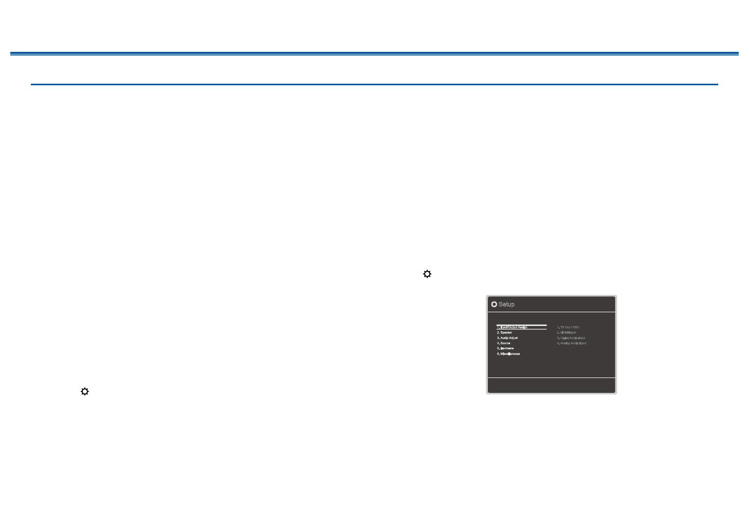
5. Press .
The Setup menu is displayed on the TV screen.
Setup
1. Input/Output Assign
4. Source
6. Miscellaneous
5. Hardware
2. Speaker
3. Audio Adjust
1. TV Out / OSD
4. Analog Audio Input
2. HDMI Input
3. Digital Audio Input
7
Front Panel Rear Panel Remote
Contents
Connections
Playback
Setup
6. Select "6. Miscellaneous" - "Firmware Update" - "Update via USB" with the
cursors in order, then press ENTER.
Setup
1. Input/Output Assign
4. Source
6. Miscellaneous
5. Hardware
2. Speaker
3. Audio Adjust
1. Tuner
4. Lock
2. Firmware Update
3. Initial Setup
If "Firmware Update" is grayed out and cannot be selected, wait for a while
until it starts up.
7. Press ENTER with "Update" selected, and start update.
During the update, the TV screen may go black depending on the program
to be updated. In such a case, check the progress on the display of the
unit. The TV screen will remain black until the update is completed and the
power is turned on again.
During the update, do not turn the power off, or disconnect or reconnect the
USB storage device.
When "Completed!" is displayed, the update is complete.
8. Disconnect the USB storage device from the unit.
9. Press
ON/STANDBY on the main unit to turn the unit into standby mode.
The process is completed, and your rmware is updated to the latest version.
Do not use on the remote controller.
If an Error Message is Displayed
If an error occurs, "Error! -" is displayed on the display of the unit. (""
represents an alphanumeric character.) Refer to the following descriptions and
check.
Error Code
-70:
The USB storage device cannot be recognized, the rmware le is not present
in the root folder of the USB storage device, or the rmware le is for another
model. Check if the USB storage device or USB cable is securely inserted to
the POWER OUT port of the unit.
Connect the USB storage device to an external power source if it has its own
power supply.
-51:
The rmware le is for another model, or the rmware le is corrupted. Retry
from the download of the rmware le.
Others:
After removing the power plug once, insert it to the outlet, and then start the
operation from the beginning.
8
Contents
Connections
Playback
Setup
Front Panel Rear Panel Remote
Part Names
Front Panel
For details, see ( p9)
9
Contents
Connections
Playback
Setup
Front Panel Rear Panel Remote
1. ON/STANDBY button
2. MUSIC OPTIMIZER button: Turns on/off the MUSIC OPTIMIZER function that
improves the quality of the compressed audio.
3. BLUETOOTH indicator: Lights up when this unit and a BLUETOOTH-enabled
device are connected.
4. DOLBY ATMOS indicator: Lights up when Dolby Atmos signals are reproduced
in appropriate listening mode.
5. Remote control sensor: Receives signals from the remote controller.
The reception range of the remote controller is within a distance of approx.
16´/5 m, and an angle of 20° in vertical direction and 30° to right and left.
6. ZONE A/B button: Selects an audio output destination from among "ZONE A",
"ZONE B" and "ZONE A+B". ( p56)
7.
INFO button: Switches the information on the display and is used to operate
RDS ( p55).
8. DIMMER button: Switches the brightness of the display with three levels. It
cannot be turned off completely.
9. Display ( p10)
10.
SETUP button: You can display advanced setting items on the TV and the
display to have a more enjoyable experience with this unit. ( p77)
11.
Cursor buttons ( / / / ) and ENTER button: Select an item with the
cursors, and press ENTER to conrm your selection. When using TUNER, use
them to tune in to stations. ( p51)
12.
RETURN button: Returns the display to the previous state while setting.
13.
MASTER VOLUME
14.
PHONES jack: Connect headphones with a standard plug (ø1/4"/6.3 mm).
15.
LISTENING MODE button: Switches the listening mode ( p61) by
pressing "STEREO", "MOVIE/TV" and "MUSIC" repeatedly.
16.
Input selector buttons: Switches the input to be played.
17.
TONE CONTROL button: Adjusts the sound quality. Press / of "TREBLE",
"VOCAL" or "BASS" respectively. ( p59)
18.
SETUP MIC jack: Connect the supplied speaker setup microphone. ( p96)
10
Front Panel Rear Panel Remote
Contents
Connections
Playback
Setup
Display
1. Speaker/Channel display: Displays the output channel that corresponds to the
selected listening mode.
2. Displays the audio output destination.
A: Outputs audio only to the main room (ZONE A).
B: Outputs audio only to the separate room (ZONE B).
AB: Outputs audio to both the main room (ZONE A) and separate room (ZONE
B).
3. Lights in the following conditions.
: Headphones are connected.
: Connected by BLUETOOTH.
HDMI: HDMI signals are input and the HDMI input is selected.
DIGITAL: Digital signals are input and the digital input is selected.
4. Lights according to the type of input digital audio signal and the listening
mode.
5. Lights in the following conditions.
RDS: Receiving RDS broadcasting.
TUNED: Receiving AM/FM radio.
FM ST: Receiving FM stereo.
SLEEP: Sleep timer is set. ( p91)
AUTO STBY: Auto Standby is set. ( p92)
6. Blinks when muting is on.
7. Displays various information of the input signals.
 
11
Contents
Connections
Playback
Setup
Front Panel Rear Panel Remote
Rear Panel
For details, see ( p12)
12
Contents
Connections
Playback
Setup
Front Panel Rear Panel Remote
1. HDMI OUT jacks: Transmit video signals and audio signals with an HDMI
cable connected to a TV.
2. HDMI IN jacks: Transmit video signals and audio signals with an HDMI cable
connected to an AV component.
3. POWER OUT port: You can also supply power (5 V/1 A) to the Streaming
media player connected to the HDMI IN terminal of this unit with a USB cable.
( p42) The playback function of music les and power supply to smart
phones/tablets, or other devices are not supported.
4. Power cord
5. DIGITAL IN OPTICAL/COAXIAL jacks: Input TV or AV component digital audio
signals with a digital optical cable or digital coaxial cable.
6. TUNER AM/FM terminal: Connect the supplied antennas.
7. AUDIO IN jacks: Input TV or AV component audio signals with an analog audio
cable.
8. ZONE B PRE/LINE OUT jacks: Output audio signals with an analog audio
cable connected to a pre-main amplier or a power amplier in a separate
room (ZONE B).
9. SUBWOOFER PRE OUT jacks: Use the subwoofer cable to connect the
supplied powered subwoofer. A maximum of two powered subwoofers can be
connected. (Purchase a second powered subwoofer separately.) The same
signal is output from each SUBWOOFER PRE OUT jack.
10.
SPEAKERS terminals: Connect the supplied speakers with speaker cables.
13
Contents
Connections
Playback
Setup
Front Panel Rear Panel Remote
Remote Controller
1. ON/STANDBY button
2. Input selector buttons: Switches the input to be played.
3. Play buttons: Used for playback operation of a BLUETOOTH-enabled device.
If the unit is switched to "CEC MODE" using the MODE button, an HDMI CEC
function-enabled AV component can be operated. (Depending on the device,
operation may not be possible.)
4. Q (QUICK MENU) button: Pressing this button during playback can make
settings such as "HDMI" and "Audio" quickly on the TV screen while playing. (
p93)
5. Cursor buttons and ENTER button: Select an item with the cursors, and press
ENTER to conrm your selection.
6. button: Display advanced setting items on the TV or the display to have a
more enjoyable experience with this unit. ( p77)
7. TONE button: Adjusts the sound quality. ( p59)
8. LISTENING MODE button: Select a listening mode ( p61).
9. DIMMER button: Switches the brightness of the display with three levels. It
cannot be turned off completely.
10.
CLEAR button: Deletes all characters you have entered when entering text on
the TV screen.
11.
MEMORY button: Used to register AM/FM radio stations. ( p53)
12.
SLEEP button: Set the sleep timer. Select the time from "30 min", "60 min" and
"90 min". ( p60)
13.
ZONE A/B button: Selects an audio output destination from among "ZONE A",
"ZONE B" and "ZONE A+B". ( p56)
14.
Input selector cursors: Switches the input to be played.
15.
button: Switches the information on the display and is used to operate RDS
( p55).
16.
button: Returns the display to the previous state while setting.
17.
button: Temporarily mutes audio. Press the button again to cancel muting.
18.
VOLUME buttons
19.
AUDIO SEL button: When a device is connected to two or more audio input
terminals for one input selector, you can select which audio input signal to
play.
20.
M.OPT button: Turns on/off the MUSIC OPTIMIZER function that improves the
quality of the compressed audio.
14
Front Panel Rear Panel Remote
Contents
Connections
Playback
Setup
21.
MODE button: Switches between automatic tuning and manual tuning for
AM/FM stations ( p51). Also, when an HDMI CEC function-enabled AV
component is connected to this unit, you can switch "3. Play buttons" between
"CEC MODE" and "RCV MODE" (normal mode).
15
Front Panel Rear Panel Remote
Contents
Connections
Playback
Setup
Speaker/Subwoofer
Front & Height Speakers
The supplied Front & Height Speakers are designed as a system with Dolby
enabled speakers, a type of height speaker, added to their top panels. Dolby
enabled speakers are special speakers designed to face the ceiling, so that the
sound is heard from overhead by bouncing the sound off the ceiling. The Front
& Height Speakers have left and right designations. Place the speaker labeled
“LEFT” on its back on the left side as you face the front of your listening area, and
place the speaker labeled “RIGHT” on its back on the right side of the listening
area.
The grille net cannot be removed.
1. Wall mount hole: the speaker system may be mounted to a wall by suspending
speakers on wooden screw using the wall mount hole.
Wooden wall mount screw is not included. Please consult with a
construction service personnel and prepare screw considering its type,
material, and length so it provides sufcient support. Moreover, please also
install a reinforcement panel, anchor, etc. if necessary.
Our company bears no responsibility in the case of accident or injury
sustained due to improper installation, insufciently mounting, misuse,
natural disaster, etc.
2. Speaker jack (for Height Speaker): Use the included speaker cable to connect
to the main unit.
9mm
4mm
Notice ( p20)
16
Front Panel Rear Panel Remote
Contents
Connections
Playback
Setup
3. Speaker jack (for Front Speaker): Use the included speaker cable to connect
to the main unit.
Do not place objects on the speaker system. The speaker system may drops
or fall over by losing balance and may cause an injury.
Notice ( p20)
17
Front Panel Rear Panel Remote
Contents
Connections
Playback
Setup
Center Speaker
The grille net cannot be removed.
1. Speaker jack: Use the included speaker cable to connect to the main unit.
2. Wall mount hole: The speaker system may be mounted to a wall by
suspending speakers on wooden screw using the wall mount hole.
Wooden wall mount screw is not included. Please consult with a
construction service personnel and prepare screw considering its type,
material, and length so it provides sufcient support. Moreover, please also
install a reinforcement panel, anchor, etc. if necessary.
Our company bears no responsibility in the case of accident or injury
sustained due to improper installation, insufciently mounting, misuse,
natural disaster, etc.
Do not place objects on the speaker system. The speaker system may drops
or fall over by losing balance and may cause an injury.
9mm
4mm
200mm
Notice ( p20)
18
Front Panel Rear Panel Remote
Contents
Connections
Playback
Setup
Surround Speakers
The supplied Surround Speakers have left and right designations.
The grille net cannot be removed.
1. Wall mount hole: The speaker system may be mounted to a wall by
suspending speakers on wooden screw using the wall mount hole.
Wooden wall mount screw is not included. Please consult with a
construction service personnel and prepare screw considering its type,
material, and length so it provides sufcient support. Moreover, please also
install a reinforcement panel, anchor, etc. if necessary.
Our company bears no responsibility in the case of accident or injury
sustained due to improper installation, insufciently mounting, misuse,
natural disaster, etc.
9mm
4mm
2. Speaker jack: Use the included speaker cable to connect to the main unit.
Do not place objects on the speaker system. The speaker system may drops
or fall over by losing balance and may cause an injury.
Notice ( p20)
19
Front Panel Rear Panel Remote
Contents
Connections
Playback
Setup
Powered Subwoofer
MIN MAX
OUTPUT LEVEL
LINE INPUT
LINE INPUT
1. Status indicator
Lights off: Subwoofer in standby mode or disconnected from power source.
Blue: Subwoofer on.
The status indicator lights blue when low frequency sound is being passed
through the speaker.
The indicator does not light in the normal dialog or high frequency sound.
The indicator does not indicate that power supply of the subwoofer has
turned on.
With the Auto Standby function, the subwoofer automatically turns on when
an input signal is detected in standby mode. If there is no signal or there is
a weak signal for a while, the subwoofer automatically switches to standby.
2. LINE INPUT: This RCA input should be connected to the SUBWOOFER PRE
OUT on your AV receiver with supplied subwoofer cable.
3. OUTPUT LEVEL control: This control is used to adjust the volume of the
subwoofer.
4. Power cord
Notice ( p20)
20
Front Panel Rear Panel Remote
Contents
Connections
Playback
Setup
Notice
Do not place objects on the speaker system. The speaker system may drops
or fall over by losing balance and may cause an injury.
Do not place on a shaky platform, sloping surface, or other unstable place.
The speaker system may drop or fall over by losing balance and may cause
an injury.
Please select an installation site that has stable oor. If placed on a long-ber
carpet, the bers may contact the oscillator panel and cause irregular noise.
Install the unit away from the tuner's antenna cable. Noise may be generated
if the two are too close together. If this happens, keep the main unit away from
the antenna and antenna cable.
If a television or other device is nearby, noise interference may be produced
by the speakers due to electrical interference, etc. even if audio device power
is disconnected. If such noise interference is problematic, further separate the
speakers.
The speaker unit for this product uses an extremely strong magnet. Do not
place drivers or other metallic objects near the front of the speaker system.
Doing so may cause injury from objects being attracted or damage the
oscillation panel. Moreover, do not place cash cards, oppy disks, or other
magnetic media near the speaker. The magnetic eld may cause those items
to be unusable or lose data.
This unit is not designed with anti-magnetic shielding. Nearby CRT televisions
and computers may experience screen color distortion due to the presence the
magnetic eld. In such cases, move the speakers further away before use.
This unit is capable of regular music playback. However, if any of the following
special signals are input, circuits may burnout due to excessive current.
Please exercise caution.
1. Noise resulting from incorrect FM channel reception
2. Noise from oscillator, electronic music device, or other high-frequency
component
3. Audio Check CD and other special signal sounds
4. Feedback from microphone
5. Sound produced when tape recorder is fast forwarded
6. When amplier is reverberating
7. Shock sound when plugging and unplugging pin cord or other connection
jacks
Maintenance
Periodically wiped the top and side surfaces of this product with a soft cloth.
When particularly dirty, soak the cloth in a diluted neutral cleaning solution and
squeeze out excess liquid before cleaning. Then, nish wiping with a dry cloth.
If using a chemical cloth, please read the warning label afxed to the cleaning
product.
  • Page 1 1
  • Page 2 2
  • Page 3 3
  • Page 4 4
  • Page 5 5
  • Page 6 6
  • Page 7 7
  • Page 8 8
  • Page 9 9
  • Page 10 10
  • Page 11 11
  • Page 12 12
  • Page 13 13
  • Page 14 14
  • Page 15 15
  • Page 16 16
  • Page 17 17
  • Page 18 18
  • Page 19 19
  • Page 20 20
  • Page 21 21
  • Page 22 22
  • Page 23 23
  • Page 24 24
  • Page 25 25
  • Page 26 26
  • Page 27 27
  • Page 28 28
  • Page 29 29
  • Page 30 30
  • Page 31 31
  • Page 32 32
  • Page 33 33
  • Page 34 34
  • Page 35 35
  • Page 36 36
  • Page 37 37
  • Page 38 38
  • Page 39 39
  • Page 40 40
  • Page 41 41
  • Page 42 42
  • Page 43 43
  • Page 44 44
  • Page 45 45
  • Page 46 46
  • Page 47 47
  • Page 48 48
  • Page 49 49
  • Page 50 50
  • Page 51 51
  • Page 52 52
  • Page 53 53
  • Page 54 54
  • Page 55 55
  • Page 56 56
  • Page 57 57
  • Page 58 58
  • Page 59 59
  • Page 60 60
  • Page 61 61
  • Page 62 62
  • Page 63 63
  • Page 64 64
  • Page 65 65
  • Page 66 66
  • Page 67 67
  • Page 68 68
  • Page 69 69
  • Page 70 70
  • Page 71 71
  • Page 72 72
  • Page 73 73
  • Page 74 74
  • Page 75 75
  • Page 76 76
  • Page 77 77
  • Page 78 78
  • Page 79 79
  • Page 80 80
  • Page 81 81
  • Page 82 82
  • Page 83 83
  • Page 84 84
  • Page 85 85
  • Page 86 86
  • Page 87 87
  • Page 88 88
  • Page 89 89
  • Page 90 90
  • Page 91 91
  • Page 92 92
  • Page 93 93
  • Page 94 94
  • Page 95 95
  • Page 96 96
  • Page 97 97
  • Page 98 98
  • Page 99 99
  • Page 100 100
  • Page 101 101
  • Page 102 102
  • Page 103 103
  • Page 104 104
  • Page 105 105
  • Page 106 106
  • Page 107 107
  • Page 108 108
  • Page 109 109
  • Page 110 110
  • Page 111 111
  • Page 112 112

ONKYO HT-S5915 Owner's manual

Category
AV receivers
Type
Owner's manual

Ask a question and I''ll find the answer in the document

Finding information in a document is now easier with AI