Page is loading ...

- 1 -
Our instruments' quality level is the results of the product continuous
development. This can bring about differences between the information written
in this manual and the instrument that you have purchased. We cannot entirely
exclude errors in the manual, for which we apologize.
The data, figures and descriptions contained in this manual cannot be legally
asserted. We reserve the right to make changes and corrections without prior
notice.
REV. 1.0
10 jan. 2007
LP PYRA 03

- 2 -
LP PYRA 03
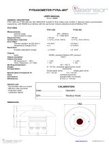
1 Introduction
LP PYRA 03 pyranometer measures the irradiance on a plane surface (Watt/ m2).
Measured irradiance ( Global Irradiance) is the result of the sum of direct solar
irradiance and of diffuse irradiance.
LP PYRA 03 is a Second Class pyranometer in accordance with ISO 9060 and with the
criteria of the WMO “Guide to Meteorological Instruments and Methods of
Observation’”, fifth edition (1983).
The pyranometer is produced in three versions:
LP PYRA 03 PASSIVE *
LP PYRA 03 AC ACTIVE ,4..20 mA CURRENT output
LP PYRA 03 AV ACTIVE , 0..1** or 0..5 or 0..10 V VOLTAGE output, to
be defined at the order.
* Using SICRAM Module VP 472 it is possible to connect passive pyranometer to
Indicator D09847.
** 0..1 output version can be connected to indicator HD2302.0 using SICRAM Module
VP 474. The indicator reads directly in W/m2.
2 Working Principle
LP PYRA 03 pyranometer is based on a thermopile sensor. The thermopile sensitive
surface is coated with a black matt paint, which allows the pyranometer not to be
selective at different wave lengths. The pyranometer spectral range is determined by
the transmission of the glass dome type K5.
Radiant energy is absorbed by the thermopile black surface, thus creating a
difference of temperature between the center of the thermopile (hot junction) and the
pyranometer body (cold junction). Thanks to the Seebeck effect, the difference of
temperature between hot and cold junction is converted into a Difference of
Potential.
In order to grant the thermopile a proper thermal insulation from the wind and reduce
the sensitivity to thermal irradiance, LP PYRA 03 is equipped with a 4mm thick
dome which is 32mm in outer diameter. The dome protects the thermopile from the
dust, which might change spectral sensitivity if ,it lies on the black surface,
To prevent internal condensation forming on the internal side of the dome under
certain climatic conditions, three silica gel tablets are inserted inside the pyranometer
to absorb humidity.

- 3 -
3 Installation and Mounting of the Pyranometer for the
Measurement of Global Radiation:
• PYRA 03 pyranometer is to be mounted in an easy-to-reach location in order to
clean the dome regularly and carry out maintenance. At the same time, make sure
that no buildings, constructions, trees or obstructions exceed the horizontal plane
where the pyranometer lies. If this is not possible, select a site where obstructions
in the path of the sun from sunrise to sunset do not exceed 5 degrees of elevation.
N.B The presence of obstructions on the horizon line affects significantly the
measurement of direct irradiance.
• Pyranometer is to be located far from any kind of obstruction, which might
reflect sunlight (or sun shadow) onto the pyranometer itself.
• In compliance with ISO TR9901 standard and WMO recommendations, when
the pyranometer is used without the white shade disk, it is to be positioned so that
its connector is pointed to the North Pole, if the instrument is used in the
Northern Hemisphere, and to the South Pole, if used in the Southern Hemisphere.
In any case, it is better to follow this suggestion even when the shade disk is
applied.
• In order to allow an accurate horizontal positioning of the instrument, use the
holes on the pyranometer body or suitable accessories (figure 1,2).
59 mm
62 mm
Fixing
hole M5
Fixinghole M5
32 mm
46 mm
32 mm
Fixing hole
for LPSP2
LP PYRA 03 AC
LP PYRA 03 AV
to be fix to
a mast
82 mm
89 mm
LP PYRA 03 AC
LP PYRA 03 AV
t
o be fix To LP S2
Fig 1

- 4 -
LP S2
500 mm
16 mm
LP SP2
LP PYRA 03 +
LP S2 LP PYRA 03 AC,
LP PYRA 03 AV
to be fixed
to LP S2
Fig. 2
HD2003.77
40 mm
LP PYRA 03 +
HD 2003.77
LP PYRA 03 AC,
LP PYRA 03 AV +
HD 2003.77
LP SP2

- 5 -
4 Electrical Connection and Requirements for Electronic
Readout Devices:
LP PYRA 03 is produced in 3 versions, LP PYRA 03, LP PYRA 03 AC and LP
PYRA 03 AV.
• LP PYRA 03 pyranometer is passive and it does not require any power supply.
• LP PYRA 03 AC, AV are active and need power supply.
Required voltage is as follows:
8-30 Vcc for LP PYRA 03 AC and LP PYRA 03 AV with 0..1V and 0..5V autput
supply.
14-30 Vcc for LP PYRA 03 AV with 0..10 V output.
• All version are supplied with a 4 pole connector.
• The optional cable is terminated with a connector at one end and it is made of
PTFE UV-proof. It is provided with 3 wires and a braided wire (shield). Cable
colors and connector poles are matched as follow (figure 3):
Fig.3
LP PYRA 03
Connector Function Color
A Shield ( ) Black
B Vout(+) Red
C Vout (-) Blue
D No connection White
LP PYRA 03 AC
Connector Function Color
A Shield ( ) Black
B Positive (+) Red
C Negative (-) Blue
D No connection White
LP PYRA 03 AV
Connector Function Color
A Shield ( ) Black
B (+) Vout Red
C (-) Vout e (-)Vcc Blue
D (+) Vcc White
A
D
B
C
A
B
C
D

- 6 -
• LP PYRA 03 pyranometer is to be connected either to a millivoltmeter or to a
data acquisition system. Typically, the pyranometer output signal does not exceed
20 mV. In order to better exploit the pyranometer features, the readout instrument
should have a 1μV resolution.
Fig. 4
• LP PYRA 03 AC is to be connected to a DMM and a power supply as show below
(Figure 5).To read the signal, the load resistance must be ≤500Ω
LP PYRA 03 AC
+Vcc
I out
Power Supply
+
+
-
-
DMM
C
B
Fig. 5
• LP PYRA 03 AV is to be connected to a DMM and a power supply as show
below (Figure 6). To read the signal, the load resistance must be ≥ 100kΩ
Fig. 6
+
-
Thermopile
LP PYRA 03
Blue RED
Screen (black)
B
C
LP PYRA 03 AV
+Vout
-Vcc,
- Vout Power Supply
+
+
-
-
DMM
+ Vcc
C
D
B

- 7 -
5 Maintenance:
In order to grant measurement high accuracy. It is important to keep the outer glass
dome clean. Consequently, the more the dome will be kept clean, the more
measurements will be accurate. You can wash it using water and standard papers for
lens, and if necessary using pure ETHYL alcohol. After using alcohol, clean again
the dome with water only.
6 Calibration and Measurements:
LP PYRA 03
The pyranometer S sensitivity (or calibration factor) allows to determine global
irradiance by measuring a signal in Volts at the thermopile ends. The S factor is
measured in μV/(Wm-2).
• Once the difference of potential (DDP) has been measured at the ends of the
sensor, the Ee irradiance is obtained applying the following formula:
Ee= DDP/S
where;
Ee: is irradiance expressed in W/m2,
DDP: is the difference of potential expressed in μV measured by the
multimeter,
S: is the calibration factor in μV/(W/m2) shown on the pyranometer
label (and mentioned in the calibration report).
LP PYRA 03 AC
The pyranometer sensitivity is set so that:
4..20 mA = 0..2000 W/m2
To obtain irradiance the following procedure is to be applied:
-once you know the current ( Iout) absorbed by the instrument and measured with the
DMM, following formula must be applied:
(
)
mAIe out
E4125
−
⋅
=
where;
Ee: Irradiance in W/m2,
Iout: current in mA absorbed by the pyranometer
LP PYRA 03 AV
The pyranometer sensitivity is set so that according to the version:
0..1 V = 0..2000 W/m2
0..5 V = 0..2000 W/m2
0..10 V = 0..2000 W/m2
To obtain irradiance the following procedure is to be applied:

- 8 -
-once you know the instrument output voltage (Vout) measured with the DMM,
following formula must be applied:
oute VE
⋅
=2000 for the version 0…1 V
oute VE
⋅
=400 for the version 0…5 V
oute VE
⋅
=200 for the version 0…10 V
where;
Ee: Irradiance in W/m2,
Vout: Output voltage (in Volt) measured by the voltmeter
Each Pyranometer is factory calibrated it is marked by its own calibration factor. To
exploit all LP PYRA 03 Features it is highly recommended that the calibration be
checked annually.
The instruments and the equipment of Delta Ohm Photometry-Radiometry
meteorological laboratory grant the calibration of pyranometers according to the
WMO specifications and ensure that measurements are traceable to the international
standards.
7 Technical Specifications:
Typical sensitivity: 10 μV/(W/m2) LP PYRA 03
4..20 mA (0-2000 W/m2) LP PYRA 03 AC
0..1,5,10V(0-2000 W/m2) LP PYRA 03 AV
Impedance: 33 Ω ÷ 45 Ω
Measuring Range: 0-2000 W/m2
Viewing angle: 2π sr
Spectral range: 305 nm ÷ 2800 nm (50%)
(Dome transmission) 335 nm ÷ 2200 nm (95%)
Operating Temperature: -40 °C ÷ 80 °C
Dimensions: figure 1
Weight: 0.45 Kg

- 9 -
Technical Specifications According to ISO 9060
1- Response Time: <30 sec
(95%)
2- Zero off-set:
a) response to a 200W/m2
thermal radiation: < 25 W/m2
b) response to a 5K/h change in
ambient temperature: <⏐6 ⏐W/m2
3a- Long-term instability: <⏐±2.5⏐ %
(1 year)
3b- Non-linearity: <⏐±2⏐ %
3c- Response according to the cosine law: < ⏐±22⏐ W/m2
Cosine Response
3d- Spectral selectivity: < ⏐±7⏐ %
3e- Response depending on temperature: <8 %
Temperature response
3f- Tilt response: <⏐±4⏐ %

- 10 -
8 Ordering Codes
ORDERING CODE ARTICLE
LP PYRA 03 Second Class Pyranometer according to
ISO 9060. It is Provided with spirit
level, 4 pole plug and Calibration
Report.
LP PYRA 03 AC Second Class Pyranometer according to
ISO 9060. It is Provided with spirit
level, 4 pole plug and Calibration
Report. 4..20 mA signal Output
LP PYRA 03 AV Second Class Pyranometer according to
ISO 9060. It is Provided with spirit
level, 4 pole plug and Calibration
Report. 0..1V, 0..5V, 0..10V signal
output (to be defined when order)
CP AA 1.5 4 pole plug with UV proof cable,
L=5m.
CP AA 1.10 4 pole plug with UV proof cable,
L=10m.
LP SP2 Shade disk for pyranometer LP PYRA
03.
LP S2 Mounting kit including a support for
LP PYRA 03 pyranometers, fastener
screws of the pyranometer to the
support and a support mast.
LP SP2+ LP S2 Mounting kit LP SP2 and LP S2
HD2003.77 Mounting kit to fix LP PYRA 03 to a φ
40mm mast. Fastener screws of the
pyranometer to the support and LP SP2
shade disk also included in the
mounting kit.
VP 472 SICRAM module for DO9847K for
Pyranometers and Albedometers. The
signal produced by the thermopile of
pyranometer can be read in mV or
W/m2. The thermopile sensitivity can
be set from 5 to 30 mV(kWm-2).
VP 474 SICRAM module to connect the
pyranometer to HD2302.0 indicator.
The instrument read directly in W/m2.

- 11 -

CE CONFORMITY
Safety EN61000-4-2, EN61010-1 LEVEL 3
Electrostatic discharge EN61000-4-2 LEVEL 3
Electric fast transients EN61000-4-4 LEVEL 3
Voltage variations EN61000-4-11
Electromagnetic interference susceptibility IEC1000-4-3
Electromagnetic interference emission EN55020 class B
This guarantee must be sent together with the instrument to our service centre.
N.B.: Guarantee is valid only if coupon has been correctly filled in all details.
RENEWALS
Date Date
Inspector Inspector
Date Date
Inspector Inspector
Date Date
Inspector Inspector
Instrument type LP PYRA 03
Serial number
GARANZIA
GUARANTEE
GARANTIE GARANTIA
GUARANTEE CONDITIONS
All DELTA OHM instruments have been subjected to strict tests and are guaranteed for 24 months
from date of purchase. DELTA OHM will repair or replace free of charge any parts which it considers
to be inefficient within the guarantee period. Complete replacement is excluded and no request of
damages are recognized. The guarantee does not include accidental breakages due to transport,
neglect, incorrect use, incorrect connection to voltage different from the contemplated for the
instrument. Furthermore the guarantee is not valid if the instrument has been repaired or tampered
by unauthorized third parties. The instrument has to be sent to the retailer without transport charge.
For all disputes the competent court is the Court of Padua.
RoHS
2002/95/EC

- 1 -
LP PYRA … S / LP PYRHE 16 S ENGLISH
RS485 MODBUS-RTU connection Rev. 2.0 – 31/01/2017
SETTING THE RS485 COMMUNICATION PARAMETERS OF LP PYRA…S PYRANOMETERS
AND LP PYRHE 16 S PYRHELIOMETER WITH A STANDARD COMMUNICATION PROGRAM
Before connecting the sensor to the RS485 network, an address must be assigned and
the communication parameters must be set, if different from the factory preset.
The setting of the parameters is performed by connecting the sensor to the PC in one
of the following two ways:
A. By using the optional CP24 cable, with built-in RS485/USB converter. In this
connection mode, the sensor is powered by the PC USB port. To use the cable, it is
necessary to install the related USB drivers in the PC.
B. By using the supplied 8-pole M12 female connector or the optional CPM12-8D…
cable and a generic RS485/USB or RS485/RS232 converter. In this connection
mode, it is necessary to power the sensor separately. If a RS485/USB converter is
used, it is necessary to install the related USB drivers in the PC.
NOTES ON THE INSTALLATION OF UNSIGNED USB DRIVER: before installing unsigned USB driver into operating
systems starting from Windows 7, it is necessary to restart the PC by disabling the driver signing request. If
the operating system is 64-bit, even after installation the request of driver signing have to be disabled each
time the PC is restarted.
PROCEDURE FOR SETTING THE PARAMETERS:
1. Start with the sensor not powered (if the CP24 cable is used, disconnect one end
of the cable).
2. Start a communication program, such as Hyperterminal. Set the Baud Rate to
57600 and set the communication parameters as follows (the sensor is connected
to a COM type port):
Data Bits: 8
Parity: None
Stop Bits: 2
In the program, set the COM port number to which the sensor will be connected.
3. Switch the sensor on (if the CP24 cable is used, connect both ends of the cable).
Power supply
or
CPM12-8D… cable Red
Blue
Brown
White
Senso
r
M12
male connector
CP24
cable
Senso
r
M12
connector

- 2 -
4. Wait until the sensor transmits the & character, then send (within 10 seconds
from the sensor power on) the @ command and press Enter.
Note: if the sensor does not receive the @ command within 10 seconds from power
on, the RS485 MODBUS mode is automatically activated. In such a case, it is
necessary to switch off and on again the sensor.
5. Send the command CAL USER ON.
Note: the command CAL USER ON is disabled after 5 minutes of inactivity.
6. Send the serial commands given in the following table to set the RS485 MODBUS
parameters:
Command
R
es
p
onse Descri
p
tion
CMAnnn &
|
Set RS485 address to nnn
Ranging from 1 to 247
Preset on 1
CMBn &
|
Set RS485 Baud Rate
n=0 ⇒ 9600
n=1 ⇒ 19200
Preset on 1 ⇒ 19200
CMPn &
|
Set RS485 transmission mode
n=0 ⇒ 8-N-1 (8 data bits, no parity, 1 stop bit)
n=1 ⇒ 8-N-2 (8 data bits, no parity, 2 stop bits)
n=2 ⇒ 8-E-1 (8 data bits, even parity, 1 stop bit)
n=3 ⇒ 8-E-2 (8 data bits, even parity, 2 stop bits)
n=4 ⇒ 8-O-1 (8 data bits, odd parity, 1 stop bit)
n=5 ⇒ 8-O-2 (8 data bits, odd parity, 2 stop bits)
Preset on 2 ⇒ 8-E-1
CMWn &
|
Set receivin
g
mode after RS485 transmission
n=0 ⇒ Violate protocol and go in Rx mode right after Tx
n=1 ⇒ Respect protocol and wait 3.5 characters after Tx
Preset on 1 ⇒ Respect the protocol
7. You can check the parameters setting by sending the following serial commands:
Command
R
es
p
onse Descri
p
tion
RMA Addres
s
Read RS485 address
RMB Baud Rate
(0,1)
Read
RS485 Baud Rate
0 ⇒ 9600
1 ⇒ 19200
RMP T
x
Mode
(0,1,2,3,4,5)
Read RS485 transmission mode
0 ⇒ 8-N-1
1 ⇒ 8-N-2
2 ⇒ 8-E-1
3 ⇒ 8-E-2
4 ⇒ 8-O-1
5 ⇒ 8-O-2
RMW R
x
Mode
(0,1)
Read receivin
g
mode after RS485 transmission
0 ⇒ Violate protocol and go in Rx mode right after Tx
1 ⇒ Respect protocol and wait 3.5 characters after Tx
Note: it is not required to send the CAL USER ON command to read the settings.

- 3 -
READING OF THE MEASURES WITH THE MODBUS-RTU PROTOCOL WHEN THE SENSOR
IS IN OPERATING CONDITIONS (INSTALLED IN A NETWORK)
In MODBUS mode, you can read the values measured by the sensor through the
function code 04h (Read Input Registers). The following table lists the quantities
available with the appropriate register address:
Address
Q
uantit
y
Forma
t
0 Temperature in °C (x10) [if available in the model] 16-bit Integer
1 Temperature in °F (x10) [if available in the model] 16-bit Integer
2 Solar radiation in W/m2 16-bit Integer
3 Status register
bit0=1 ⇒ solar radiation measurement error
bit1=1 ⇒ temperature measurement error
bit2=1 ⇒ configuration data error
bit3=1 ⇒ program memory error
16-bit Integer
4 Average solar radiation in W/m2
The average refers to the last 4 measures
16-bit Integer
5 Signal (in mV x 100) generated by the sensor 16-bit Integer
OPERATING MODE: the sensor enters RS485 MODBUS-RTU mode after 10 seconds from
power on. In the first 10 seconds from power on the sensor does not reply to requests
from the MODBUS master unit. After 10 seconds, it is possible to send MODBUS
requests to the sensor.
CONNECTION:
Connecto
r
Function
Colo
r
1 Power supply negative Blue
2 Power supply positive Red
3 Not connected
4 RS485 A/- Brown
5 RS485 B/+ White
6 Case Shield (Black)
7 Not connected
8 Not connected
The RS485 output is not isolated.
The metallic case of the sensor should preferably be grounded ( ) locally. In
this case, do not connect the shield of the CPM12-8D… cable to prevent
ground loops.
Only if it is not possible to ground locally the metallic case of the sensor,
connect the the shield of the CPM12-8D… cable to ground ( ).
Senso
r
Discharge
r
Case
RS485
output
Power supply
Senso
r
M12
male connector CPM12-8D…
cable

- 4 -
Connection of RS485 output
CABLES:
CP24 PC connecting cable for the MODBUS parameters configuration. With
built-in RS485/USB converter. 8-pole M12 connector on sensor side
and A-type USB connector on PC side.
CPM12-8D.2 Cable with 8-pole M12 connector on one end, open wires on the
other side. Length 2 m.
CPM12-8D.5 Cable with 8-pole M12 connector on one end, open wires on the
other side. Length 5 m.
CPM12-8D.10 Cable with 8-pole M12 connector on one end, open wires on the
other side. Length 10 m.
Power suppl
y
5…30 Vdc
R
ed
Blu
e
Brown
White
CPM12-8D… cable
Senso
r
M12
male connector
PLC, data logger o
r
RS485/USB or RS485/RS232
converter for PC
Othe
r
senso
r
s with
RS485 output
Termination Termination

- 1 -
LP PYRA … S12 series ENGLISH
Pyranometers with SDI-12 output Rev. 1.1 – 05/10/2016
The pyranometers of the LP PYRA…S12 series are
solar radiation sensors with digital SDI-12 output.
Due to its low power consumption, SDI-12 standard
is becoming very popular for environmental
monitoring, expecially in battery/solar panel-powered
data acquisition systems.
The sensors are compatible with version 1.3 of SDI-
12 protocol and can be connected to the data logger
HD32MT.3 or to any other data logger with SDI-12
input.
Electrical connections are made through an M12
connector.
The sensors are factory calibrated.
An NTC 10KΩ temperature sensor allows detecting the
pyranometer internal temperature.
TECHNICAL CHARACTERISTICS
Solar radiation sensor Thermopile
Temperature sensor NTC 10KΩ (it detects the pyranometer internal temperature)
Power supply 7…30 Vdc
Power consumption < 200 µA
Output digital SDI-12
Connection 8-pole M12 connector
Measuring range and optical
characterists
Same as LP PYRA … series
CONNECTION:
More SDI-12 sensors can be connected in parallel. The distance between a sensor and the
acquisition system should not exceed 60 m. Before connecting the instrument to an SDI-12
network containing other sensors, set the address by using the proper SDI-12 command
reported in the commands table.
Data logger
input
P
y
ranomete
r
Surge
Protector
Case
SDI-12
output
Power supply
P
y
ranometer M12
male connector CPM12-8D…
cable
Power su
pp
l
y
Other SDI-12
sensor
Other SDI-12
sensor

- 2 -
M12 Connector Function Cable color
1 Power supply negative (GND)
SDI-12 output negative Blue
2 Power supply positive (+Vdc) Red
3 Not connected
4 Not connected
5 SDI-12 output positive White
6 Case Shield (Black)
7 Not connected
8 Not connected
The metallic case of the pyranometer should preferably be grounded ( )
locally. In this case, do not connect the shield of the CPM12-8D… cable to
prevent ground loops.
Only if it is not possible to ground locally the metallic case of the pyranometer,
connect the the shield of the CPM12-8D… cable to ground ( ).
SDI-12 PROTOCOL
The protocol communication parameters are:
• baud rate: 1200
• data bits: 7
• parity: Even
• stop bits: 1
The communication with the instrument is performed by sending a command in the following
form:
<Address><Command>!
with <Address> = address of the instrument the command is sent to
<Command> = type of operation requested to the instrument
The instrument reply is as follows:
<Address><Data><CR><LF>
with <Address> = address of the instrument which replies
<Data> = information sent by the instrument
<CR> = ASCII character Carriage Return
<LF> = ASCII character Line Feed
The sensors come with a factory address preset to 0. The address can be modified by using
the proper SDI-12 command reported in the following table.
The following table reports the SDI-12 commands available. To comply with the SDI-12
standard, the instrument address is indicated in the table with the letter a.

- 3 -
SDI-12 Commands
Command Instrument reply Description
a! a<CR><LF> Verifies the presence of the
instrument.
aI! allccccccccmmmmmmvvvssssssss<CR><LF>
with:
a = address of the instrument (1 character)
ll = SDI-12 compliant version (2 characters)
cccccccc = manufacturer (8 characters)
mmmmmm = instrument model (6 characters)
vvv = firmware version (3 characters)
ssssssss = serial number (8 characters)
⇒ Example of response:
013DeltaOhmLP-PYRA0016051518
with:
0 = instrument address
13 = SDI-12 version 1.3 compliant
DeltaOhm = manufacturer’s name
LP-PYR = instrument model
A00 = firmware version A.0.0
16051518 = serial number
Requests for information from
the instrument.
aAb!
Where:
b = new
address
b<CR><LF>
Note: if the b character is not an acceptable address, the
instrument responds with a instead of b.
Modification of the instrument
address.
?! a<CR><LF> Request of the address of the
instrument. If more than one
sensor is connected to the bus,
a conflict occurs.
TYPE M (START MEASUREMENT) AND TYPE C (START CONCURRENT MEASUREMENT) COMMANDS
Irradiance, signal internal level and internal temperature
aM!
aC!
atttn<CR><LF>
with: ttt = number of seconds necessary for the instrument
to make the measure available (3 characters)
n = number of detected variables (1 character for
aM!, 2 characters for aC!)
Note: ttt = 000 means that datum is immediately available.
Request to execute the
measurement.
aD0! a+n+w…w+v…v+t…t<CR><LF>
with:
n = content of the status register
w…w = irradiance in W/m2
v…v = signal internal level in mV
t…t = internal temperature in the set unit of
measurement (default °C)
⇒ Example of response: 0+0+228.7+3.294+25.1
probe address = 0
content of the status register = 0
irradiance = 228.7 W/m2
signal internal level = 3.294 mV
internal temperature = 25.1 °C
Note: the status register normally contains zero; a value
different from zero indicates an error condition.
Reads the measurement.

- 4 -
Command Instrument reply Description
Irradiance and internal temperature
aM1!
aC1!
atttn<CR><LF>
with: ttt = number of seconds necessary for the instrument
to make the measure available (3 characters)
n = number of detected variables (1 character for
aM1!, 2 characters for aC1!)
Note: ttt = 000 means that datum is immediately available.
Request to execute the
measurement.
aD0! a+w…w+t…t<CR><LF>
with:
w…w = irradiance in W/m2
t…t = internal temperature in the set unit of
measurement (default °C)
⇒ Example of response: 0+228.7+25.1
probe address = 0
irradiance = 228.7 W/m2
internal temperature = 25.1 °C
Reads the measurement.
Internal temperature
aM2!
aC2!
atttn<CR><LF>
with: ttt = number of seconds necessary for the instrument
to make the measure available (3 characters)
n = number of detected variables (1 character for
aM2!, 2 characters for aC2!)
Note: ttt = 000 means that datum is immediately available.
Request to execute the
measurement.
aD0! a+t…t<CR><LF>
with t…t = internal temperature in the set unit of
measurement (default °C)
⇒ Example of response: 0+25.1
probe address = 0
internal temperature = 25.1 °C
Reads the measurement.
Signal internal level
aM3!
aC3!
atttn<CR><LF>
with: ttt = number of seconds necessary for the instrument
to make the measure available (3 characters)
n = number of detected variables (1 character for
aM3!, 2 characters for aC3!)
Note: ttt = 000 means that datum is immediately available.
Request to execute the
measurement.
aD0! a+v…v<CR><LF>
with v…v = signal internal level in mV
⇒ Example of response: 0+3.294
probe address = 0
signal internal level = 3.294 mV
Reads the measurement.
In addition to the above-mentioned commands, the sensor also implements the corresponding
commands with CRC, that require to add a 3-character CRC code at the end of the reply before
<CR><LF>. The format of these commands is obtained from the previous by adding the letter
C: aMC!, aMC1!, aMC2!, aMC3!, aCC!, aCC1!, aCC2!, aCC3!. The sensor does not implement
the type R (Continuous Measurements) commands.
/