Page is loading ...

C US
Page
Section - D7 - 79B
Form 404090
APR - 2011
Models AC2400 & AC2440
PowerLuber Grease Gun
Series “B”

Page Number - 2 Form 404090
Models AC2400 & AC2440
PowerLuber Grease Gun
NOTE: Grease cartridges are not included.
Table of Contents
General Power Tool Safety Warnings........................................2
Electrical Safety.........................................................................2
Tool Use and Care……………………........................................3
Service………………………………….....................................3
Specications............................................................................3
General Description...................................................................4
Inspection.........................................................................4
Operation...........................................................................4
Exploded View and Part List…………......................................…8
Troubleshooting....................................................................11
GENERAL POWER TOOL SAFETY WARNINGS
Read all safety warnings and instructions. Failure to
follow the warnings and instructions may result in electric
shock, re and/or serious injury.
Save all warnings and instructions for future reference.
The term “power tool” in the warnings refers to your mains-
operated (corded) power tool or battery-operated (cordless)
power tool.
1) Work area safety
a) Keep work area clean and well lit.
Cluttered or dark areas invite accidents.
b) Do not operate power tools in explosive atmo-
spheres, such as in the presence of ammable
liquids, gases or dust. Power tools create sparks which
may ignite the dust or fumes.
c) Keep children and bystanders away while operating a
power tool. Distractions can cause you to lose control.
2) Electrical safety
a) Power tool plugs must match the outlet. Never modify
the plug in any way. Do not use any adapter plugs with
earthed (grounded) power tools. Unmodied plugs and
matching outlets will reduce risk of electric shock.
b) Avoid body contact with earthed or grounded surfac-
es such as pipes, radiators, ranges and refrigerators.
There is an increased risk of electric shock if your body is
earthed or grounded.
c) Do not expose power tools to rain or wet conditions.
Water entering a power tool will increase the risk of elec-
tric shock.
d) Do not abuse the cord. Never use the cord for carrying,
pulling or unplugging the power tool. Keep cord away from
heat, oil, sharp edges or moving parts. Damaged or
entangled cords increase the risk of electric shock.
e) When operating a power tool outdoors, use an exten-
sion cord suitable for outdoor use. Use of a cord suit-
able for outdoor use reduces the risk of electric shock.
f) If operating a power tool in a damp location is un-
avoidable, use a residual current device (RCD) pro-
tected supply. Use of an RCD reduces the risk of
electric shock.
NOTE: The term “residual current device (RCD)” may
be replaced by the term “ground fault circuit interrupter
(GFCI)” or “earth leakage circuit breaker (ELCB)”.
3) Personal safety
a) Stay alert, watch what you are doing and use com-
mon sense when operating a power tool. Do not use a
power tool while you are tired or under the inuence
of drugs, alcohol or medication. A moment of inattention
while operating power tools may result in serious personal
injury.
b) Use personal protective equipment. Always wear eye
protection. Protective equipment such as dust mask, non-
skid safety shoes, hard hat, or hearing protection used for
appropriate conditions will reduce personal injuries.
c) Prevent unintentional starting. Ensure the switch is
in the off-position before connecting to power source
and/or battery pack, picking up or carrying the tool.
Carrying power tools with your nger on the switch or
energizing power tools that have the switch on invites ac-
cidents.
d) Remove any adjusting key or wrench before turning
the power tool on.
A wrench or a key left attached to a rotating part of the
power tool may result in personal injury.
e) Do not overreach. Keep proper footing and balance at
all times. This enables better control of the power tool in
unexpected situations.
f) Dress properly. Do not wear loose clothing or jewelery.
Keep your hair, clothing and gloves away from moving
parts. Loose clothes, jewelery or long hair can be caught
in moving parts.
g) If devices are provided for the connection of dust
extraction and collection facilities, ensure these are
connected and properly used. Use of dust collection can
reduce dust-related hazards.
4) Power tool use and care
a) Do not force the power tool. Use the correct power
tool for your application. The correct power tool will
do the job better and safer at the rate for which it was
designed.
b) Do not use the power tool if the switch does not turn
it on and off. Any power tool that cannot be controlled
with the switch is dangerous and must be repaired.
c) Disconnect the plug from the power source and/or the
battery pack from the power tool before making any
adjustments, changing accessories, or storing power
tools. Such preventive safety measures reduce the risk of
starting the power tool accidentally.
d) Store idle power tools out of the reach of children and
do not allow persons unfamiliar with the power tool
or these instructions to operate the power tool. Power
tools are dangerous in the hands of untrained users.

Page Number - 3
Form 404090
Models AC2400 & AC2440
PowerLuber Grease Gun
TOOL USE AND CARE
• Do not use the PowerLuber if the switch does not turn it on
and off. A PowerLuber that cannot be controlled with the
switch is dangerous and must be repaired.
• Disconnect the plug from the power source before making
any adjustments, changing accessories or storing Power-
Luber. Such preventive safety measures reduce the risk of
starting the PowerLuber accidentally.
• Store idle PowerLubers out of the reach of children and do
not allow persons unfamiliar with the PowerLuber or these
instructions to operate it. PowerLubers are dangerous in the
hands of untrained users.
• Maintain PowerLubers. Check for misalignment or binding
of moving parts, breakage of parts and any other condition
that may affect the PowerLuber’s operation. If damaged,
have the PowerLuber repaired before use.
• Be sure your power supply agrees with the nameplate
marking. Voltage decrease of more than 10% will cause
loss of power and overheating. If this tool does not operate,
check power supply.
• Do not continue to hold down trigger if grease gun is stalled.
This could damage the motor or cause re.
• Use only accessories that are recommended for this model.
Only accessories that are capable of handling 7000 PSI
(482 bar) should be used.
SERVICE
• Service must be performed only by qualied repair per-
sonnel. Service or maintenance performed by unqualied
personnel may increase the risk of injury.
• When servicing a PowerLuber, use only Lincoln replace-
ment parts. Use of unauthorized parts may increase the risk
of injury and will void the warranty.
SPECIFICATIONS
Basic PowerLuber Model AC2400
Operating Power, Volt------------------------------ 120 AC
Rated Current---------------------------------------- 2 amps
Maximum Operating Pressure, psi (bar) ------ 7,000 (482)
Grease Reservoir Capacity, oz. (cm³) -------- 14.5 (411)
Operating Temperature Range, °F(°C) ------ 0 to122 (-18 to+50)
Operating Current, at
1,000 psi (69 bar) ---------------------------- 1.6 amps
7,000 psi (482bar)---------------------------- 2.75 amps
Lubricant (Grease) --------------------------------- up to NLGI #2
Grease output, oz./min(cm³/min) at 1000psi (69bar)
(“L” Setting)------------------------------------- 3.6 (106.5)
Grease output per stroke, oz(cm³) (“L” Setting)
at 1000psi(69bar)-----------------------------. 021 (.62)
Weight, lbs. (kg) ------------------------------------ 8.2 (3.76)
Accessories:
Outlet Hose Model 1230
-pressure rating, psi(bar) 7,500 (510)
-length of the Hose, In (mm) 30 (760)
Minimum Gauge for Cord Sets
Volts Total Length of Cord in Feet/Meters
Ampere Rating 120V 25 / 7.6 50 / 15.2 100 / 30.5 150 / 45.7
240V 50 / 15.2 100 / 30.5 200 / 61.0 300 / 91.4
More
Than
Not More
Than AWG
0 6 18 16 16 14
6 10 18 16 14 12
MODELS
Sales Model Basic PowerLuber Case
AC2440 AC2400 286240
Grease gun can develop high pressure - up to 7,000 psi
(482 bar). Use safety glasses and gloves for protection
during operation. Keep hands clear of the exposed rubber
portion of hose.
Extreme pressure may cause nozzle extension of whip hose
to burst. Use only Lincoln APPROVED hoses and follow
whip hose instructions and warnings.
e) Maintain power tools. Check for misalignment or
binding of moving parts, breakage of parts and any
other condition that may affect the power tool’s opera-
tion. If damaged, have the power tool repaired before
use. Many accidents are caused by poorly maintained
power tools.
f) Keep cutting tools sharp and clean. Properly main-
tained cutting tools with sharp cutting edges are less
likely to bind and are easier to control.
g) Use the power tool, accessories and tool bits, etc.,
in accordance with these instructions, taking into
account the working conditions and the work to be
performed. Use of the power tool for operations different
from those intended could result in a hazardous situation.
5) Service
a) Have your power tool serviced by a qualied repair
person using only identical replacement parts. This will
ensure that the safety of the power tool is maintained.
Warning! To reduce the risk of injury, the user must
read the instruction manual.
Separate collection. This product must not be
disposed of with normal household waste.

Page Number - 4 Form 404090
Models AC2400 & AC2440
PowerLuber Grease Gun
INSPECTION
1. Visually inspect for damaged, loose or missing parts.
2. If tool is worn or damaged, remove from service. Contact an
authorized service center for damage assessment or repair.
OPERATION
Changing “L” or “H” Mode
To change the mode of operation:
To prevent damage to the gears in the transmission, the
motor must be completely stopped before changing the
lever to the “L” or “H” (low or high) mode of operation.
“L” (low output/high pressure)
“H” (high output/low pressure)
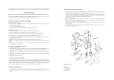
When motor is not running, push the red lever (Fig. 1) until
letter “L” or “H” will be completely visible in the window.
In case the red lever is not completely shifted/engaged,
hold this lever and bump the switch to engage gears.
High output is recommended if the tool is used to lubricate
large bearings not requiring high pressure, beyond 3,000 psi
(206 bar). Also, high output is recommended if tool is used to
rell small reservoirs of automatic lubrication systems.
Low output is recommended if the tool is used in construction,
agricultural and mining applications and general lubrication.
Low output will provide the maximum pressure of up to 7,000
psi (482 bar) the tool is capable of producing.
Prime the PowerLuber after each rell or grease cartridge
change. Prime the gun before using it to lubricate grease
points.
To prime, operate the gun until grease ows from the hose.
Use vent valve (Fig. 1) to expel air pockets.
The double insulated system is intended to protect the
user from shock resulting from a break in the tool’s internal
insulation. Observe all normal safety precautions to avoid
electrical shock.
GENERAL DESCRIPTION
Appropriate use
The Lincoln PowerLuber was developed for manual lubrication
of grease points and includes a safety valve, stroke counter,
output lever, whip hose with coupler and 6-foot power cord.
The PowerLuber is driven by a small electric motor connected
to a three-stage planetary gear reducer. The rotary motion
of the motor is converted into a reciprocating motion of the
plunger through an eccentric and yoke mechanism. The
PowerLuber is a positive displacement single acting pump.
Safety Valve
The safety valve (Fig. 1) is factory set to relieve pressure
above 7000 psi (482 bar). The valve also is an indicator of the
bearing and lubrication line conditions. If grease comes out
of the safety valve, it indicates a clogged or tight bearing or
tting or line. Correct this before continuing lubrication with the
PowerLuber.
Stroke counter
The tool is equipped with capability for calibration. This is ac-
complished by measuring (weighing) grease ow output and
dividing the weight of grease by number of strokes. Simply put
your thumb on the stroke counter button (Fig. 1) during opera-
tion of the tool and count.
Some OEM’s are recommending the exact amount of grease
to lubricate critical bearings. By counting the strokes you will
know how much grease has been dispensed to lubricate the
bearing. Here is the table of the grease output vs. number of
strokes.
Stroke count Output/stroke
oz. gram
10 0.20 5.7
15 0.30 8.5
20 0.40 11.4
Note: Lincoln recommends this feature only on low output/high
pressure mode.
Variable output switch
The variable speed switch permits motor speed control, the
more the trigger is depressed the higher speed of the motor
and therefore the higher the grease output of the gun.
Double insulation
The electric PowerLuber utilizes a double insulated motor de-
sign for safety. The double insulation eliminates the need for a
three wire grounded cord. All exposed metal parts are isolated
from the internal metal motor components with a double layer
of protection insulation. Double insulated tool do not need
to be grounded.

Page Number - 5
Form 404090
Models AC2400 & AC2440
PowerLuber Grease Gun
©
© Indicates change
Figure 1

Page Number - 6 Form 404090
Models AC2400 & AC2440
PowerLuber Grease Gun
Figure 2
Installing Grease Cartridge
1. Unscrew the grease tube assembly from the PowerLuber.
2. Visually check the follower seal lip direction before load-
ing a new cartridge. The follower seal lip must be directed
toward the follower handle or rear side for cartridge loading.
See Fig. 2. (To change the direction of the follower seal,
unscrew tube cap from grease tube assembly and pull on
the handle to remove follower seal from tube. Flip follower
seal over and reassemble.)
3. Pull back on the follower handle and latch the follower rod
groove into the slot on the tube cap.
4. Remove the plastic cap from the grease cartridge and
insert cartridge into the container tube.
5. Remove the pull tab from grease cartridge and screw
grease tube assembly into pump assembly.
6. Release follower rod from slot. Purge air from pump. See
air purging instructions.
Air pockets in the cartridge lubricant will cause the gun to
lose its prime.
Removing Empty Grease Cartridge
1. Pull back on the follower handle until the follower rod is fully
extended and latch the follower rod groove into the slot on
the tube cap.
2. Unscrew the grease tube assembly from the PowerLuber.
3. Carefully release the follower handle to eject the empty
cartridge from container tube.
To Convert Gun to Allow Filling From Bulk
Container or Filler Pump
1. Unscrew the grease tube assembly cap from the grease
tube assembly. Pull on the follower handle to extract the
follower and spring from the grease tube assembly.
2. Grasp follower between thumb and forenger and ip the
follower lip from the rear to the front side.
NOTE: The follower resembles a cup. When the gun is as-
sembled for use with bulk lubricant, the cup opens toward
the pump assembly.
3. Reassemble follower into grease tube assembly and posi-
tion with the follower handle so that the grease tube assem-
bly cap can be tightened onto the container tube.
To Fill The Gun from Bulk Container
1. Remove pump assembly from grease tube assembly.
2. Pack lubricant into cavity of the pump assembly.
3. Insert the open end of the grease tube assembly into lubri-
cant (see Fig. 3). Slowly pull the follower handle back while
pushing the grease tube assembly deeper into the lubricant
to prevent air pockets from being pulled into the grease
tube assembly.
4. When the follower rod is fully extended, pull it sideways to
latch the rod groove into the keyhole slot in the grease tube
assembly cap.
5. Loosely assemble the pump assembly to the grease tube
assembly. Release the follower rod from the grease tube
assembly cap and disengage the follower rod from the fol-
lower by rotating the follower handle. Push the follower rod
into the grease tube assembly. Slowly unscrew the grease
tube assembly from the pump assembly until lubricant
oozes from the interface. Tighten grease tube assembly
into the pump assembly.
Figure 3
Figure 4
To Fill The Gun with a Filler Pump
1. Engage the follower rod with the follower by rotating the fol-
lower handle.
2. Insert the gun vent/bulk ll valve into the ller pump socket
(see Fig. 4).
3. Operate the ller pump to ll the container. When the fol-
lower rod groove is exposed, the grease tube assembly is
lled. The follower rod will be extended approximately 8
inches (20 cm). Do not overll!
4. Disengage the follower rod from the follower by rotating the
follower handle.
5. Push the follower rod into the grease tube assembly.
Rear side Front side

Page Number - 7
Form 404090
Models AC2400 & AC2440
PowerLuber Grease Gun
Remove Air Pocket! Air pocket at grease inlet will prevent
grease from being pumped. Unscrew the vent/bulk ll
valve two full turns to remove small air pockets trapped
in this area. If the air pocket is substantial and no grease
ows from coupler after trigger is pulled for 15 seconds,
see the following steps.
To Expel Air Pockets
1. Withdraw the follower rod from the grease tube assembly
cap and engage it with the follower by rotating the follower
handle.
2. Unscrew the vent/bulk ll valve two turns. Exert force on
the follower handle until grease ows through the opening
in the vent/bulk ll valve.
3. Tighten the vent/bulk ll valve.
4. Pull the trigger in short bursts to operate gun until trapped
air is expelled. Disengage the follower rod from the follower
by rotating the follower handle. Push the follower rod into
the grease tube assembly.
5. If step 2 fails, unscrew the grease tube assembly 3 turns
from the pump assembly.
6. Exert force on the follower handle until lubricant oozes
from the grease tube assembly and pump assembly inter-
face.
7. Tighten grease tube assembly into the pump assembly.
Disengage the follower rod from the follower by rotating the
follower handle. Push the follower rod into the grease tube
assembly.

Page Number - 8 Form 404090
Models AC2400 & AC2440
PowerLuber Grease Gun
©
© Indicates change
Figure 5

Page Number - 9
Form 404090
Models AC2400 & AC2440
PowerLuber Grease Gun
© Indicates change
©
Figure 6

Page Number - 10 Form 404090
Models AC2400 & AC2440
PowerLuber Grease Gun
© Indicates change
Service Parts List
Item Description Part Number
1 Flexible Hose 30” w/Gasket 1230
2 Coupler 5852
3 Packing 34793
4Follower Assembly Kit 93485
5Grease Tube Assembly 271882
6 Gasket Kit (Hose) 271884
7 Seal 271889
8 Handle Kit (Grease tube) 286090
9 Rod, Follower Kit 286091
10 Hose Clip Kit 286092
11 Coupler Cap Kit 286093
12 Gear Selector Kit 286097
13 Decal Kit 286101
14 Cover Pump Kit 286106
15 Yoke Kit 286107
16 Stroke Indicator 286108
17 Plunger Kit 286109
18 Stud Kit 286110
19 Roller Kit 286111
20 Spring Selector 286113
21 Vent/Balk Valve Kit 286134
22 Motor & Plate Kit 286155
23 Cord Kit 286156
24 Cord Protector Kit 286157
25 Trigger Kit 286179
26 Driver Assembly 286285
27 Gear Set Kit 286286
28 Check Valve Kit 286306
29 Housing Pump with Bearing 286307
30 Vent Valve Kit 286315
31 Gasket Kit (Relief valve) 286316
32 Relief Valve Kit 286317
33 Handle Kit 286333
34 Pump Assembly Kit 286334
35 Seal Retainer Kit 286335
36 Seal Rubber Kit 286336
-- Hardware Kit 286190
-- Strap 1414
-- Case 286240

Page Number - 11
Form 404090
Models AC2400 & AC2440
PowerLuber Grease Gun
TROUBLESHOOTING
Condition Possible Cause Corrective Action
Motor fails to run. No power Check power cord connection
with outlet.
Loose wire connection. Disassemble handle and check
wiring for loose connection.
Faulty switch. Replace switch.
Worn motor brushes. Replace motor.
Burned motor. Replace motor.
PowerLuber fails to Grease tube assembly is out of grease. Check that grease tube
dispense grease. assembly has grease.
Loss of prime. Repeat priming operation.
Ball check item 19 is not functioning. Remove Items 19 and clean and
inspect ball seat area.
PowerLuber continues Air may be trapped in several locations Empty grease tube
to lose prime. in container after bulk lling. assembly, rell and repeat
priming instructions.
Follower may be binding in grease *Replace grease tube assembly
tube assembly. Item 2.
*Disassemble grease tube
assembly and clean.
*Be sure that follower has properly
entered the grease cartridge.
Or
*Verify that the follower is not
caught on the rim of the grease
cartridge.

Page Number - 12 Form 404090
Models AC2400 & AC2440
PowerLuber Grease Gun
THIS PAGE LEFT BLANK INTENTIONALLY.
Americas:
One Lincoln Way
St. Louis, MO 63120-1578
USA
Phone +1.314.679.4200
Fax +1.800.424.5359
Europe /Africa/Middle East
Lincoln GmbH
Heinrich-Hertz-Str. 2-8
69190 Walldorf - Germany
Phone/Fax +49.6227.33-0/-259
www.lincolnindustrial.de
Asia/Pacic:
51 Changi Business Park
Central 2
#09-06 The Signature
Singapore 486066
Phone +65.6588.0188
Fax +65.6588.3438
© Copyright Lincoln Industrial
Corporation 2009
Printed in USA
Web site:
www.lincolnindustrial.com
/