Page is loading ...

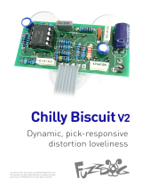
SpectreVerb
Spring Reverb tones, from
slapback to spacey ambient
Contents of this document are ©2015 Pedal Parts Ltd.
No reproduction permitted without the express written
permission of Pedal Parts Ltd. All rights reserved.

Schematic
BOM
R1 1M
R2 1M
R3 22K
R4 12K
R5 10K*
R6 10K
R7 10K
R8 22K
R9 33K
R10 10K
R11 10K
R12 15K
R13 15K
R14 10K
R15 15K
R16 1K
R17 22K (12K)
R18 470R
R19 100K
R20 10K
R21 10K
R22 2K2 (CLR)
IC1 TL074
IC2 PT2399
IC3,4 78L05**
D1 1N4001
DEP 2KB
DWE 5KB (25KB)
ATT 10KB
C1 1u
C2 470n
C3 470n
C4 1n
C5 2n2
C6 100n
C7 10n
C8 100n
C9 100n
C10 100n
C11 100n
C12 470n
C13 10u elec
C14 10u elec
C15 1u elec
C16 2u2 elec
C17 10u elec
C18 100u elec
C19 100u elec
C20 100u elec
R17 and Dwell values in blue are for the
out-there mega-dwell self-oscillation mod.
*use higher value to get closer to unity. 18K is good.
**see note on next page re placement of IC3 and 4.

The 5V power regulators, IC3 and
4, should be placed in the opposite
orientation to how they’re shown
on the silkscreen. The image on
the first page of this document is
correct.
The power and signal pads on the
PCB conform to the FuzzDog Direct
Connection format, so can be
paired with the appropriate
daughterboard for quick and easy
offboard wiring.
Be very careful when soldering the
diode, LED and regulators. They’re
very sensitive to heat. You should
use some kind of heat sink
(crocodile clip or reverse action
tweezers) on each leg as you solder
them. Keep exposure to heat to a
minimum (under 2 seconds).
The striped leg (cathode) of the
diode goes into the square pad.
The long leg (anode) of the electrolytic capacitors go into the square pads. The
large 100u capacitors should lay flat over the other components as shown in the
image on the first page. This will give you plenty of clearance in the enclosure.
Snap the small metal tag off the pots so they can be mounted flush in the box.
Pot mounts on the back side of the board. You can use vertical-mount pots or
just wire up ‘normal’ ones. It’s a good idea to place the pots in their holes in the
enclosure when you’re soldering them in place on the PCB. That way you know
they’re going to line up ok. Best way to do it is to solder a single pin of each pot
in place, then do a visual check to see that they’re all sitting at the same height. If
not, melt the joints and readjust any that are off.
If your pots have protective plastic covers you should
remove them, as there won’t be space for them to sit side
by side on the board. You’ll have to keep a decent gap
between the pots and the underside of the board. Place a
strip of thick card between them and the board when
soldering to keep them even.
You should solder all other board-mounted components
before you solder the pots. Once they’re in place you’ll have
no access to much of the underside of the board. Solder
the BTDR-2H brick last. Make sure it’s quite close to the
board or it will stop the pots sitting tight to the enclosure.
Pots should be placed as shown >>>
Swapping out the parts for the DWELL mod will change
that control from subtle to extreme, with self-oscillations
at the far right of the turn. Worth doing.
1 2 3
PCB Layout ©2014 Pedal Parts Ltd.

Test the board!
UNDER NO CIRCUMSTANCES will troubleshooting help
be offered if you have skipped this stage. No exceptions.
Once you’ve finished the circuit it makes sense to test is before starting on
the switch and LED wiring. It’ll cut down troubleshooting time in the long
run. If the circuit works at this stage, but it doesn’t once you wire up the
switch - guess what? You’ve probably made a mistake with the switch.
Solder some nice, long lengths of wire to the board connections for 9V, GND,
IN and OUT. Connect IN and OUT to the jacks as shown. Connect all the
GNDs together (twist them up and add a small amount of solder to tack it).
Connect the battery + lead to the 9V wire, same method. Plug in. Go!
If it works, crack on and do your switch wiring. If not... aw man.
At least you know the problem is with the circuit. Find out why, get it
working, THEN worry about the switch etc.
BATTERY
IN OUT
Your nice, new circuit board
INCLUDING WIRED POTS!!!!
IN 9V GND OUT

(if using a daughterboard please refer to the relevant document)
Wire it up - DC only version
This circuit is standard, Negative GND. Your power supply should be
Tip Negative / Sleeve Positive. That’s the same as your standard pedals
(Boss etc), and you can safely daisy-chain your supply to this pedal.
The BOARD GND connections don’t all have to connect to one point.
They can be daisy-chained around the circuit, using larger connection
points (such as jack socket lugs) for multiple connections. As long as
they all connect together in some way.
L
E
D
BOARD
OUT
BOARD
9V
BOARD
GND
BOARD
GND
BOARD
GND
BOARD
INPUT
+
IN
OUT
L
E
D
BOARD
GND
BOARD
LED+

(if using a daughterboard please refer to the relevant document)
Wire it up - with battery
This circuit is standard, Negative GND. Your power supply should be
Tip Negative / Sleeve Positive. That’s the same as your standard pedals
(Boss etc), and you can safely daisy-chain your supply to this pedal.
The BOARD GND connections don’t all have to connect to one point.
They can be daisy-chained around the circuit, using larger connection
points (such as jack socket lugs) for multiple connections. As long as
they all connect together in some way.
FuzzDog.co.uk
L
E
D
BOARD
OUT
BOARD
9V
BOARD
GND
BOARD
GND
BOARD
GND
BOARD
INPUT
BATTERY
+
IN
OUT
L
E
D
BOARD
GND
BOARD
LED+
+
Just because the
FuzzDog enclosure
won’t take a battery,
there’s nothing
stopping you using a
bigger box.

Drilling template
Hammond 1590B
60 x 111 x 31mm
SpectreVerb
Recommended drill sizes:
Pots 7mm
Jacks 10mm
Footswitch 12mm
DC Socket 12mm
This template is a rough guide only. You should ensure correct marking of your
enclosure before drilling. You use this template at your own risk.
Pedal Parts Ltd can accept no responsibility for incorrect drilling of enclosures.
FuzzDog.co.uk
35mm
17.5mm
It’s a good idea to drill
the holes for the pots
8mm to give yourself
some wiggle room
unless you’re a drill ninja

It’s tight in there,
but it does fit!
/