Page is loading ...

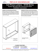
Assembly Instructions
MOTUM TEACHERS DESK
FIXED HEIGHT LEFT HAND
Document #: 179717 REVISED: 5/2022
MODEL NUMBERS
58001, 58003, 58005, AND 58007
A digital copy of these assembly instructions can be found at
https://smithsystem.com/wp-content/uploads/2022/03/MOTUM-TEACHERS-DESK-
FIXED-HEIGHT-ASSEMBLY-INSTRUCTIONS-LEFT-179717.pdf
For video assembly instructions, scan the QR code link, or visit
https://www.youtube.com/watch?v=p6AvBcqOus0

Hardware and Components
REVISED: 11/2020
For 72” Models Only (58005 and 58007)
Document #: 179717

Hardware and Components
Document #: 179717 REVISED: 11/2020
ITEM #13 –TEACHERS DESK HARDARE PACK COMPONENTS
USED ON
58003 and 58007
USED ON
58001 and 58005

Hardware and Components
Document #: 179717 REVISED: 11/2020
PANEL LETTER PART NUMBER DESCRIPTION QTY.
A P14400 TD STRAIGHT LEG SIDE PANEL 1
B P14399 TD U LEG SIDE PANEL 1
D P14403 TD MAIN FRONT PANEL LH 1
C P14401 TD 120 FRONT PANEL LH 1
PANEL LETTER PART NUMBER DESCRIPTION QTY.
E P14390 TD 24X60" TOP LH 1
PANEL LETTER PART NUMBER DESCRIPTION QTY.
H P14392 TD 24X72" TOP LH 1

Special Notes:
•TOOLS REQUIRED:
•Framing square.
•OPTIONAL TOOLS:
•Wood Clamps, ¼” bit extender
•Check that all components are accounted for and undamaged before assembling.
•Please assemble the product in a clean and dry area.
•Clean the product with a mild cleaner and a damp cloth.
•It is highly recommended to assemble this with 2 people.
Document #: 179717 REVISED: 11/2020

Assembly Instructions
Document #: 179717 REVISED: 11/2021
1. Place wood top on clean smooth surface upside down with the pilot holes facing up,
fasten 2x item #7 to item A using 4x fasteners item #1 using the supplied T25 Torx bit
item # 4.
2. Position Panel B as shown, centering the panel to create equal gaps, a spacer or
credit card works well. Fasten panel #7 to item A using 4x fasteners item #1 using the
supplied T25 Torx bit item # 4. NOTE: The panel should sit on the metal finger as
shown.

Assembly Instructions
Document #: 179717 REVISED: 11/2021
REFERENCE LINES
PILOT HOLES
3. Place wood top on clean smooth surface upside down with the pilot holes and reference
lines facing up. The reference lines will be used to help align the metal components in future
steps, these are only guides final locations will vary by assembly accuracy. (Panel H is used in
these instruction, substitute panel H with panel E for 60” models)
4. THE POSITION OF COMPONENT 3 IS CRTITICAL, IT DETERMINES ALL OTHER COMPONENTS
POSTIONS AND IS THE MOST DIFFICULT TO CHANGE AFTER THE ASSEMBLY IS DONE. The outside
edge of item #3 vertical tubes should sit flush with the 3 indicated reference lines below.
5. Fasten item #3 down with 2x fasteners item #1 using the two pilot holes, confirm the location is
correct as described above and install the remaining 6x fasteners item #1.
Reference line
Reference line
Vertical Tubes

Assembly Instructions
Document #: 179717 REVISED: 11/2021
5. Slide the previously assembled panel A onto item #3, item #7 should side over the
metal lip of item #3 as shown. Do not install any fasteners at this point this board will be
removed later. It it helpful to clamp panel A to item #3.
6. Install items #5 and #4 to item #3 as shown using 4x fastener item #3, finger tighten
only.

Reference line
Flush with #12’s edge
These faces should be flush
Assembly Instructions
Document #: 179717 REVISED: 11/2021
7. Align item #12’s edge with the reference line as shown. Item #12 should be touching
Item #3 and the faces indicated below should be flush. Fasten #12 to top using 4x
fastener #1.
Install these two
fasteners first
Edges of panel D and A should
be flush as shown, a faming
square is recommended.
Edges of panel D and A should be flush as shown, a framing
square is recommended. Confirm at the top and bottom
edges are flush
8. Using 2x item #10 as spacers. Place panel D as shown. Confirm panel D and A edges
align as show. Fasten panel D with the 2x indicated fastener #1 first, confirm panel D and
A edges are still aligned and install the remaining 6x #1 fasteners

Edges of panel D and item #12
should be flush as shown, check
top and bottom before fastening,
a straight edge is recommended.
Assembly Instructions
Document #: 179717 REVISED: 11/2021
10. Place item #12 as shown. Confirm panel D and item #12 faces align as show. Fasten
item #12 with the 5x fasteners #1.
9. Align item #10’s edge with the reference line as shown. Item #10 should be touching
Item #11. Fasten #10 to top using 2x fastener #1.
Reference line
Flush with #10’s edge
These faces of item #10 and
#11 should touch

Edges of panel C and item #1 should
be parallel, the gap should be as
minimal as possible, check top and
bottom before fully fastening.
Assembly Instructions
Document #: 179717 REVISED: 11/2021
12. Place the previously assembled item #1 and panel B as shown. Attach item #8 using 2x fastener
#1 to panel C and attached item #8 to item #1 using 2x fastener #3, finger tighten only. Confirm the
gap between item #1 and panel C is constant and as minimal as possible as shown below. Fully
tighten fasteners.
11. Align item #9’s edge with the reference line as shown. Item #10 can be used as a spacer for panel
C. Insert panel C into the slot of Item #12. Place item #9 against panel C as show. Confirm that all 3x
holes on item #12 and item #9 can be seen though the slots while item #10 is in place. Fasten #12 and
#9 to panel C using 3x fastener #1 each. (Do not fasten item #9 to the panel H, this will be done in
further steps)
Reference line
Flush with #9’s edge

Assembly Instructions
Document #: 179717 REVISED: 11/2021
14-A. This step is for 58001 and 58005 only, all other models skip to step 14-B.
Remove all components from inside 19179 before inverting. Remove panel A assembly and set to
the side. Position 19179 the metal flanges should touch the metal components as shown below,
install 8x fastener #1 on the two side flanges as shown.
Reference Line / Parallel edge
No fasteners on
this back tab
These edges
will touch
13. Edge of item #1 should be parallel with the reference line as shown (depending on the assembly
process the reference line may not be flush with the edge of item #1) Align edge of tube from item #1
with the edge of the wood, NOT the face of the edge banding. Fasten #1 to panel H using 8x fastener
#1 and then faster item #9 to panel H using 3x fastener #1.
Align edge of tube from item #1 with the edge of the
wood(brown surface), NOT the face of the edge banding.

Assembly Instructions
Document #: 179717 REVISED: 11/2021
15. Place item #6 as shown, Fasten #6 to the tube of item #3 using 2x fastener #3, finger tighten only.
Install 2x fastener #2. (Fastener #2 is a self drilling fastener, it will create 2 new holes in item 19179)
Confirm there is a constant gap between 19179/19178 and the tube of item #3. Tighten the 2x
fastener #2.
14-B. This step is for 58003 and 58007 only.
Remove all components from inside 19178 before inverting. Remove panel A assembly and set to the
side. Position 19178 front face is flush with the edge of wood as shown below, allow for a small gap
between the tube of item #3 and hinge. (door is shown removed for illustrative purposes), install 6x
fastener #1 in the 6x holes of 19178 as shown.
Line up face
this this edge
Allow for a small
gap between hinge
and this tube

Assembly Instructions
Document #: 179717 REVISED: 11/2021
17. Place item #14 between the bottom of 19179/19178 and the casters that came with 19179/19178.
Install the 16x fasteners that came with 19179/19178.
16. Replace panel A, item #10 can be used as a spacer. Confirm that panel A and D are
flush, a framing square is recommended. Install 3x fastener #1 into panel A

Assembly Instructions
Document #: 179717 REVISED: 11/2021
18-B. This step is for 60” Models only (58001 and 58003).
The indicated face of item #10 should be flush with item #1 as shown. Install 2x fasteners #1 into
panel E.
18-A. This step is 72” Models only (58005 and 58007), for all other models skip to step 18-B.
Line up item #15 with the reference line. Install 8x fasteners from hardware pack supplied
with item #15 into panel H.
Reference line
These faces
should be flush

Assembly Instructions
Document #: 179717 REVISED: 11/2021
20. Flip desk onto casters as shown.
19. Unlock all casters, on a soft, clean surface flip the desk on its front face as shown.
/