Page is loading ...

Ultra Elite
®
Facepiece
TAL 013 (L) Rev. 5 © MSA 2010 Prnt. Spec. 10000005389 (I) Mat. 10042830
Doc. 10000015248
MAINTENANCE AND REPAIR

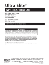
ULTRA ELITE FACEPIECE COMPONENTS
Item Part No. Description
1 804804 Upper Lens Ring
2 10031102 SpeeD-ON Head Harness Assembly
2a 10031105 SpeeD-ON Head Harness Straps
3 804806 1/4 Turn Screw Kit (4 Req’d)
4 817262 Rubber Head Harness
5 805020 Lens Super Hardcoat
6 804805 Lower Lens Ring
7 10034500 Slide Cover
7a 10033115 Component Housing Cover (Push-to-Connect)
7b 804819 Component Housing Cover (1/4 Turn)
8 494297 Buckles (2 Req’d)
9 804807 Buckle Ass’y with D-Ring (2 Req’d)
10 See Chart Facepiece Blank
11 804822 Valve Seat (2 Req’d)
12 804823 Valve Disc (2 Req’d)
13 804811 Component Housing Ring
14 804812 Screw Kit
15 10018621 Slide Adapter Ass’y
15a 10033115 Push-To-Connect Adapter Ass’y
15b 813556 1/4 Turn Adapter Ass’y
17 804829 Neckstrap
18 815604 Component Housing Assembly (Complete)
18a 804813 Inlet Disc
18b 804814 Valve Spider (1/4 Turn)
18c 804808 Speaking Diaphragm Retainer
18d 804809 Speaking Diaphragm
18e 815605 Component Housing with Exhalation Valve Kits
818107 Retaining Bar Spring Kit (not shown)
814459 Exhalation Valve (not shown)
18f 805011 Valve Spider (Firehawk)
19 Nosecup Assembly (with valves)
19c 495188 Medium, Black
19d 495189 Large, Black
19e 804638 Spectacle Kit
20 804821 Screw Kit (2 Req’d)
23 637865 Spacer (1/4 Turn)
24 813543 Retaining Ring (1/4 Turn)
10037791 NightFighter Bracket (not shown)
2
TAL 013 (L) Rev. 5 - 10042830
ULTRA ELITE FACEPIECE

3
TAL 013 (L) Rev. 5 - 10042830
ULTRA ELITE FACEPIECE
7a
7
7b
15b
23
24
3
12-27 in. lbs.
2a
pressure demand facepiece NFPA
Facepiece Components
Type Small Medium Large
Hycar 10048814 10048813 10048815
Silicone 805581 805580 805582
Facepiece Blank

4
TAL 013 (L) Rev. 5 - 10042830

ULTRA ELITE FACEPIECE
CLEANING AND DISINFECTING
Depending on the cleaning policy adopted, either a desig-
nated person or the user should clean each device after
each use. ANSI standards suggest that users should be
trained in the cleaning procedure. Confidence Plus
Cleaning Solution (P/N 10009971) from MSA is recom-
mended. It cleans and disinfects in one operation. It
retains its germicidal efficiency in hard water to inhibit the
growth of bacteria. It will not deteriorate rubber, plastic,
glass, or metal parts. Refer to label for user instructions.
• DO NOT use any cleaning substances that can or
might attack any part of the apparatus.
• Alcohol should not be used as a germicide
because it may deteriorate rubber parts.
• If not rinsed thoroughly, cleaning agent residue
may irritate the wearer’s skin.
1. Preparing Solution
a. Follow the instructions with the Confidence Plus
Cleaning Solution.
b. If the Confidence Plus Cleaning Solution is not
used, wash in a mild cleaning solution, rinse thor-
oughly, and submerge in a germicide solution for
the manufacturer’s recommended time.
2. Clean and Disinfect the Facepiece
a. Remove the mask mounted regulator from the face-
piece.
b. Unthread the thumb screw of NightFighter Heads-
Up Display System receiver Voicemitter Assembly,
slide the receiver from facepiece bracket.
c. Thoroughly wash the facepiece (and nosecup) in the
cleaning solution. A soft brush or sponge can be
used to clean the soiled facepiece.
d. Rinse the facepiece and components in clean,
warm (110°F) water (preferably running and
drained).
e. Clean the pressure-demand exhalation valve by
pressing in on the stem with a blunt object and
flushing with clean water.
f. Allow the facepiece to air dry. Do not dry the parts
by placing them near a heater or in direct sunlight.
The rubber will deteriorate.
g. Operate the exhalation valve by hand to be sure it
works properly.
Note: Do not force-dry the parts by placing them in a
heater or in direct sunlight. The rubber will deteriorate.
When the facepiece is thoroughly dry, store the facepiece
in the plastic bag that it was shipped in.
3. In general, only the facepiece requires cleaning and
disinfecting after each use.
4. Re-attach NightFighter Heads-Up Display System
Receiver and Voicemitter Assembly.
a. Slide receiver onto facepiece bracket.
b. Finger-tighten thumb screw.
5. Thoroughly dry the facepiece and regulator after
cleaning and disinfecting. The facepiece can trap
water, which could enter the regulator.
REMOVING THE SPEED-ON
®
HEAD HARNESS
1. To remove a damaged SpeeD-ON Head Harness from
the facepiece, lay the facepiece on a table or other flat
surface.
2. To remove a damaged rubber head strap from the
facepiece, lay the facepiece on a table or other flat
surface.
a. Grasp the facepiece lug with the thumb and forefin-
ger of one hand. Grasp the headstrap metal buckle
with the thumb and forefinger of the other hand.
b. Lift the metal buckle up with your thumb as you
stretch the facepiece lug.
c. Turn the facepiece and switch hands to pry up on
the other side of the metal buckle.
d. Pull the facepiece lug out of the metal buckle.
e. Repeat steps a through d for each remaining strap
surface.
3. To remove the bottom buckles, pull the back of the
buckle away from the rubber strap and pull slightly so
the rubber harness end-tab is at the buckle.
4. Fold the end-tab sides together, then slide each tab
through its buckle.
5. Repeat steps 3 and 4 for the other buckle.
CLEANING SPEED-ON HEAD HARNESS
Machine wash in warm water (maximum 120°F) with a
mild detergent. Hang the harness in an open area to air-
dry. Do not dry clean. Do not bleach or use abrasive
cleaners. Do not fold or store when wet.
INSTALLING THE SPEED-ON HEAD HARNESS
1. Install the harness strap buckles on the facepiece rub-
ber lug at the crown and temple locations:
a. Insert the long tab end of the rubber lug into the
metal ring.
b. Pull the entire
rubber lug
through the
metal ring.
5
TAL 013 (L) Rev. 5 - 10042830

ULTRA ELITE FACEPIECE
2. Refer to Kit 817088 Head Harness Installation instruc-
tions to attach the harness.
REMOVING THE COMPONENT HOUSING COVER
1. Remove the two component housing cover screws.
2. Remove the locking
ring, if applicable.
3. Remove the component housing cover.
a. For the 1/4 Turn Facepiece: Lift up on the cover
release hook located forward of the adapter assem-
bly opening. Once the release is lifted, remove the
cover by pulling it away from the housing. Tilt the
cover and work it over one adapter bayonet at a
time.
b. For the Firehawk Slide Facepiece: Remove the
cover by pulling it away from the housing.
c. For the Firehawk
Push-To-Connect
Facepiece: Pull the
cover to release the
retaining hook. With
the cover between
the hex flats and
flange of the adapter,
turn the adapter
counter-clockwise to
remove.
4. Unthread and remove the adapter assembly, if applic-
able. For the Firehawk Slide Facepiece, turn the cover
upside down and backwards to use the cover as a
wrench to unthread the adapter.
Note: Be careful that you do not damage internal parts of
the component housing assembly (exhalation valve,
spring, retainer, or speaking diaphragm) once the cover is
removed.
MMR EXHALATION VALVE
Do not pull the spring retainer out of component hous-
ing slots. This could damage the component housing.
Removing the Spring and Spring Retainer
1. Slide the spring retainer to one side, then, carefully
push center of the retainer down into the component
housing freeing retainer from slots in the housing. Lift
the retainer and the spring out of the component hous-
ing. Discard spring and spring retainer.
Be careful not to damage the slots or valve seat in the
component housing. If either the slots or valve seat is
damaged, the entire component housing must be
replaced. Also be careful not to damage the soft rub-
ber surface of the valve.
2. Inspect the slots in the component housing. If either
appears to be damaged or distorted replace the dam-
aged component housing.
Installing the Pressure Demand Exhalation Valve
Spring and Spring Retainer
1. Place the new spring on the new (ivory) spring retain-
er. Place the free end of the spring over the exhalation
valve boss.
Note: The retainer ends are angled. The shorter end goes
down (toward the bottom part of the component housing).
In this position, the part number on the retainer is on the
left side facing the exhalation valve (down).
2. Insert one angled end of the spring retainer all the way
into the slot on one side of the component housing.
Place the other angled end of the retainer against the
side of the housing above the slot, push the center of
retainer down (above spring), then slide the retainer
toward the bottom of the housing until the retainer
snaps into slot.
Ensure spring retainer is secured in the sides of com-
ponent housing. If the retainer does not remain secure
the component housing must be replaced.
3. Check that the spring retainer is securely engaged in
the slots of component housing.
a. Carefully lift up the center of retainer. (the retainer
might snap again)
b. Make sure the retainer is fully engaged in the slots
6
TAL 013 (L) Rev. 5 - 10042830

ULTRA ELITE FACEPIECE
of component housing.
c. Ensure that the spring is centered on the exhalation
valve.
4. Inspect the slots in the component housing. If either
appears to be damaged or distorted replace the dam-
aged component housing.
5. Install Component Housing Cover
Note: If the cover hook does not snap in place, hand-
tighten the adapter assembly clockwise until two corners
of a flat line up with the two notches in the top of the
component housing inlet. The cover should snap into
place.
Don the facepiece and check the face-to-facepiece
seal. Follow the Facepiece Fit Check procedures.
1. Don the facepiece.
2. Cycle exhalation valve by inhaling and exhaling six
times before testing the face-to-facepiece seal.
3. To check for facepiece fit, hold the palm of your hand
over the inlet connection and inhale. Hold your breath
at least 10 seconds. The facepiece should collapse
and stay collapsed against your face. If it does not,
readjust the facepiece and test again. If this does not
correct the leak, do not use the facepiece.
4. To test the exhalation valve, take a deep breath and
hold it. Block the inlet connection with the palm of
your hand and exhale. If the exhalation valve is stuck,
you may feel a heavy rush of air around the facepiece.
You may need to exhale sharply to open the valve.
INSTALLING THE ADAPTER ASSEMBLY
1. The 1/4 Turn Facepiece
a. Holding the adapter
assembly in one
hand, rotate the slip
nut so that the octa-
gon flange on the
slip nut lines up with
the octagon flange
on the adapter.
b. Thread the adapter assembly into the facepiece.
Use the spanner wrench to torque the adapter to
12-27 in.lbs. If necessary, continue to torque until
the top flat on the octagon is horizontal.
c. The bayonets must
be in a horizontal ori-
entation. If the bayo-
nets are not horizon-
tal, remove the
adapter assembly
and turn the slip nut.
d. Re-install the adapter assembly so that the bayo-
nets are horizontal when the adapter assembly is
torqued 12-27 in.lbs.
2. The Firehawk Slide Facepiece
a. Thread the slide adapter into the component hous-
ing, handtight.
b. Use the component housing cover to tighten the
adapter so that the next hex flat is aligned with the
two index marks near the top of the component
housing.
3. The Firehawk Push-To-Connect Facepiece
a. With the cover
between the hex flats
and flange of the
adapter, thread the
adapter into the com-
ponent housing.
b. Insert the tab on the cover into the slot in the lens
ring.
c. Tighten the adapter so that the top hex flat is hori-
zontal.
d. Press the cover until the retaining hook snaps into
place.
INSTALLING THE COMPONENT HOUSING COVER
1. Place the component housing cover over the adapter
assembly. Tilt and rotate the cover to work it over one
bayonet at a time, if applicable.
2. Insert the tab on the cover into the slot in the lens ring.
3. Press in on the front of the cover until the cover hook
snaps in place.
4. Install the locking ring by sliding it into the groove on
the adapter, if applicable. (Do not slide it into the
space between the slip nut flange and the adapter
flange.)
5. Place the spacers in the cover sockets under the lock-
ing ring, if applicable.
7
TAL 013 (L) Rev. 5 - 10042830

ULTRA ELITE FACEPIECE
6. Install the phillips screws and tighten.
7. Verify each of the following features.
a. The adapter bayonets are locked into a horizontal
position, if applicable, and CANNOT be rotated.
b. The slip nut is threaded completely into the face-
piece and locked securely, if applicable. It CANNOT
be rotated.
c. The metal locking ring is locked into position, if
applicable, and CANNOT be rotated.
d. There is no loose play in the assembly of parts.
7. Don the facepiece and check the face-to-facepiece
seal. Follow the Facepiece Fit Check.
REMOVING THE FACEPIECE LENS AND RING
Keep the protective papers on the lens until the lens is
completely assembled in the facepiece.
Note: Remove the adapter assembly and component
housing cover.
1. Use a phillips screw-
driver to loosen and
remove the screw from
each side of the face-
piece lens retaining
ring.
2. Remove the upper and
lower lens retaining
rings.
3. Fold the facepiece flange rubber back and pull the
lens out of the groove.
INSTALLING THE FACEPIECE LENS AND RING
1. Remove any dirt, lens fragments, or other debris from
the groove.
2. Line up the new lens
center-line marks (top
and bottom) with the
facepiece center-line
mark. Insert the top of
the lens into the
groove. Work the face-
piece rubber flange
around the lens to fully
seat the lens in the
groove. When installed
correctly, the bottom
lens center-line mark lines up with the bottom face-
piece center-line mark.
3. Moisten the facepiece lens groove and the inside of
the housing ring.
4. Install the bottom ring.
Insert the tab at the top
of the component
housing into the slot at
the bottom center of
the lower lens ring. The
tab should snap into
place.
5. Line up the top lens ring center-line with the facepiece
rubber flange center-line mark. Press the ring into
place.
6. Press the ring halves together at the top and bottom
of the facepiece so that the ends mate.
7. Install a screw on each side. Start the screws. They
should thread easily. If not, remove and reinstall the
screws to avoid cross-threading. Keep hand pressure
on both ring halves.
8. As the ring halves come together, alternate tightening
the left and right screws to be sure the rings seat
completely on the rubber flange.
Do not over-tighten. Rubber must not show between
the lens ring ends at the joint. If this happens,
reassemble.
9. Remove all lens protective papers from the new lens.
10. Re-install the component housing and the adapter
assembly.
11. Don the facepiece and check the face-to-facepiece
seal. Follow the Facepiece Fit Check.
12. Install a cover lens to protect the facepiece polycar-
bonate lens during storage.
8
TAL 013 (L) Rev. 5 - 10042830

ULTRA ELITE FACEPIECE
REMOVING THE COMPONENT HOUSING ASSEMBLY
Note: Remove the adapter assembly and the component
housing cover.
1. Use a small phillips screwdriver to remove the compo-
nent housing ring screw.
2. Grasp the ring with the
thumb and forefinger of
each hand. Gently
spread the ring halves
apart at the bottom.
3. When the facepiece
rubber is out of the ring
groove, lift the ring up
away from the face-
piece. You may need to
pull the housing down
slightly to allow enough
room to remove the
ring from between the
housing and the lower
lens ring.
4. Remove the facepiece rubber from the component
housing and pull the housing and nosecup (if installed)
out of the facepiece.
INSTALLING THE COMPONENT HOUSING ASSEMBLY
1. Slide the housing into the front of the facepiece.
2. Starting at the top
(narrow end) of the
housing, place the
housing in the face-
piece groove. Work the
rubber all the way
around the housing.
Check that the housing
is completely captured
inside the groove and
the center-lines are
lined up.
3. Moisten the facepiece housing area and the inside of
the housing ring.
4. Insert the narrow end of the ring into the space
between the lower lens ring and the facepiece housing
area.
5. Line up the component
housing ring mark with
the facepiece center-
line.
6. Starting at the top,
work the housing ring
down on the facepiece
to capture the face-
piece rubber in the ring
groove. Work your way
down each side of the
ring until the facepiece
rubber is completely
captured inside the
ring.
7. Gently squeeze the ring halves together at the bottom
of the housing. Watch the facepiece rubber at the top
as you do this. If you see any bulges or wrinkles in the
facepiece rubber, it is not captured in the groove.
Rework the ring around the facepiece rubber until
there are no bulges or wrinkles.
Bulges or wrinkles mean that the facepiece rubber is
not seated correctly in the ring. Re-install the ring to
seat it correctly. Failure to follow this warning can
cause the facepiece to leak and result in serious per-
sonal injury or death.
8. When the housing ring appears to be seated, grasp
the outside of the ring and the inside of the housing at
the top between your thumb and forefinger and
squeeze them together. Then do the same with the
ring halves at the bottom.
9
TAL 013 (L) Rev. 5 - 10042830

ULTRA ELITE FACEPIECE
9. Install the screw and
tighten using a small
phillips screwdriver.
Rubber must not extrude between the component
housing ring ends at the joint. If this happens,
reassemble.
10. Re-install the nosecup or air baffle (if used) in the
facepiece.
11. Re-install the component housing cover and adapter
assembly.
12. Don the facepiece and check the face-to-facepiece
seal. Follow the Facepiece Fit Check.
REPLACING THE SPEAKING DIAPHRAGM
1. Remove the nosecup or air baffle (if installed) from
inside the facepiece.
2. Unscrew and remove
the speaking
diaphragm retaining
ring.
3. Turn the facepiece upside down and shake out the
metal speaking diaphragm and gasket assembly.
4. Check the speaking diaphragm and gasket assembly
for damage. Replace it if it is worn or damaged.
5. Be sure that the gasket is on the diaphragm assembly.
Place the diaphragm in the retaining ring. Be sure that
the gasket side of the speaking diaphragm will be fac-
ing the component housing.
6. Replace the retaining ring and hand-tighten.
7. Re-install the nosecup or air baffle (if used) in the
facepiece.
8. Don the facepiece and check the face-to-facepiece
seal. Follow the Facepiece Fit Check.
REPLACING THE INLET GASKET AND DISC VALVE
1. Remove the component housing cover and the
adapter assembly.
2. Remove the disc from the gasket and inspect both for
wear. The disc should be very soft and pliable. Install
a new disc valve if it is damaged or hardened.
3. To install the inhalation disc valve:
a. Gently, stretch the hole in the center of the disc
valve over the gasket stem.
b. Note that the inlet
gasket has a groove
around its inside.
c. With the pull-tab facing you, insert the gasket into
the facepiece at an angle so that its groove cap-
tures the housing rim. The lower lip on the gasket
must be placed under the rim in the component
housing.
Note: It may be necessary to bend the gasket slightly to
work the groove under the rim all the way around. When
installed correctly, the gasket will lay flat in the housing,
and none of the spokes will be bent.
4. Re-install the adapter assembly.
5. Don the facepiece and check the face-to-facepiece
seal. Follow the Facepiece Fit Check.
ULTRA ELITE FACEPIECE COMPONENT HOUSING
INSPECTION
Note: Ultra Elite Facepieces can be identified by a mold-
ed emblem in the forehead area containing the word
“Ultra Elite”.
See User’s Instructions for additional illustrations and
information.
Inspect the component housing on Ultra Elite Facepieces
manufactured from July to December 2003 using the pro-
cedure below.
To locate the date code:
1. Hold the Ultra Elite Facepiece in one hand.
2. Gently pull the chin cup toward you.
3. Under a good light source, locate the stamped circle
on the inside, right side of the facepiece.
10
TAL 013 (L) Rev. 5 - 10042830

ULTRA ELITE FACEPIECE
4. If a dot is visible in either the third or fourth quadrant
of the “03” section and none in the “04” section, the
facepiece is subject to the Inspection Advisory.
Proceed with the inspection as follows:
Inspection Procedure: (see illustration)
1. For Air Purifying and Pressure Demand facepieces
(except MMR and Firehawk), unthread and remove the
adapter assembly. Component housing cover removal
is not necessary.
2. For MMR and Firehawk™ slide-to-connect facepieces:
a. Remove the two component housing cover screws
and the neckstrap.
b. Remove the locking ring (MMR only).
c. Lift up on the cover release hook, located forward
of the adapter assembly opening. With the release
lifted, the cover can be removed by pulling it away
from the housing. On MMR facepieces, tilt the cover
and work it over one adapter bayonet at a time.
d. Unthread and remove the adapter.
3. For Firehawk push-to-connect (PTC) facepieces:
a. Remove the two component housing screws and
the neckstrap.
b. Lift up on the cover release hook, located forward
of the adapter assembly opening. With the release
lifted, pull the cover away from the component
housing so that it is between the hex flats and
flange of the PTC adapter.
c. With the cover against the adapter flange, unthread
the adapter from the component housing.
4. Pull the gasket (valve spider) out. Ensure that the
white inlet disc valve remains attached to the gasket.
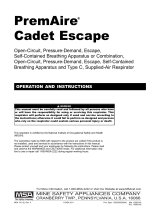
5. Inspect the flat sealing surface for dullness or discol-
oration. Refer to the photos below. Also, for refer-
ence, compare the thread finish to the sealing surface.
Note: For clearer photos, refer to this inspection advisory
on MSA’s website:
http://www.msanet.com/msanorthamerica/msaunitedstate
s/USnoticeindex.html
Normal Discolored
6. If dullness, discoloration, cracks, or breaks are noted,
do not use the facepiece. Call MSA Customer Service
at 1-877-MSA-3473 to make arrangements to return
the UltraElite Facepiece to MSA for repair.
7. If no discoloration, cracks, or breaks are noted,
reassemble the facepiece as indicated below and
return it to service.
Reassembly of Ultra Elite Component Housing Cover
and Adapter
1. Gently stretch the hole in the center of the inlet disc
valve over and onto the gasket stem.
2. With the pull-tab facing outward, insert the gasket into
the facepiece at an angle so that the groove around
the outer edge captures the housing rim. The lower lip
on the gasket must be completely under the rim in the
component housing.
Note: The gasket may need to be bent slightly to work
the lip under the rim all the way around. When installed
correctly, the gasket will lay flat in the housing and none
of the spokes will be bent.
3. For Air Purifying and Pressure Demand facepieces
(except MMR and Firehawk), reinstall the adapter
assembly.
4. For MMR facepieces:
a. Holding the adapter assembly in one hand, rotate
the slip nut so that the octagon flange on the slip
nut lines up with the octagon flange on the adapter.
b. Thread the adapter assembly into the facepiece.
c. Using a torque wrench with the spanner wrench (PN
494261), torque the adapter to a minimum 12 inlbs.
If necessary, continue to torque until the top flat on
the octagon is horizontal with a maximum torque of
27 inlbs.
d. The bayonets must be in a horizontal orientation. If
the bayonets are not horizontal, remove the adapter
assembly and turn the slip nut to the next octagon
flange alignment.
e. Re-install the adapter assembly so that the bayo-
nets are horizontal when the adapter assembly is
torqued 12 - 27 in-lbs.
f. Place the component housing cover over the
adapter assembly. Tilt and rotate the cover to work
it over one bayonet at a time.
g. Insert the tab on the cover into the slot in the lens
ring.
h. Press in on the front of the cover until the cover
hook snaps in place.
i. Install the locking ring by sliding it into the groove
on the adapter. (Do not slide it into the space
between the slip nut flange and the adapter flange.)
j. Place the neckstrap brackets and the spacers in the
cover sockets under the locking ring.
k. Install the phillips screws and tighten.
l. Verify each of the following features.
i. The adapter bayonets are locked into a horizontal
position and CANNOT be rotated.
ii. The slip nut is threaded completely into the face
piece and locked securely. It CANNOT be rotated.
iii. The metal locking ring is locked into position and
CANNOT be rotated.
11
TAL 013 (L) Rev. 5 - 10042830

ULTRA ELITE FACEPIECE
iv. There is no loose play in the assembly of parts.
4. For Firehawk slide-to-connect facepieces.
a. Thread the adapter into the facepiece.
b. Tighten the adapter hand tight. Use the component
housing cover to continue to tighten until the top
flat on the octagon is horizontal.
c. Insert the tab on the component housing cover into
the slot in the lens ring.
d. Press in on the front of the cover until the cover
hook snaps in place.
e. Place the neckstrap brackets in the cover sockets.
f. Install and tighten the Phillips screws.
g. Verify that there is no loose play in the assembly of
parts.
5. For Firehawk push-to-connect (PTC) facepieces:
a. Insert the component housing cover tab into the
lens ring slot, leave the cover loose.
b. Place the PTC adapter through the facepiece com-
ponent housing cover and thread the adapter
assembly into the facepiece hand tight.
c. Continue to tighten until the top flat of the adapter
octagon is horizontal.
Note: The octagon flats on the facepiece adapter must
align with octagon flats of component housing.
d. Press in on the front of the cover until the cover
hook snaps into place.
e. Place the neckstrap brackets into the cover sock-
ets.
f. Install the phillips screws and tighten.
g. Verify that there is no loose play in the assembly of
parts.
6. Don the facepiece and check the face-to-facepiece
seal. Follow the facepiece fit check procedures in the
user’s instructions.
Note: For questions regarding this procedure, please
contact MSA Customer Service at 1-877-MSA-3473.
12
TAL 013 (L) Rev. 5 - 10042830
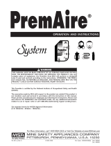
Facepiece Components
Firehawk Push-to-Connect
Adapter and Component Housing
Cover
Firehawk Slide-to-Connect
Adapter and Component Housing
Cover
Air Purifying and Pressure Demand
(Except MMR and Firehawk)
Adapter and Component
Housing Cover
Component Housing Cover
Removal Not Necessary
Screws
Locking Ring
Spacers
Gasket (Valve Spider)
Inlet Disc Valve
Neckstrap
MMR Component Housing Cover
MMR Adapter
Facepiece

ULTRA ELITE FACEPIECE
13
TAL 013 (L) Rev. 5 - 10042830
PUSH TO CONNECT (PTC)
CONTENTS
P/N 10033115 PTC Adapter
P/N 637070 Screw (2)
P/N 490134 Spider Valve
BEFORE USE
• Read and understand these instructions before
attempting to use this equipment.
• This air mask is to be used only by trained and quali-
fied personnel.
INSTALLING THE PTC (PUSH TO CONNECT)
ADAPTER ASSEMBLY AND COMPONENT HOUSING
COVER
1. Insert facepiece compo-
nent housing cover tab
into lens ring slot, leave
the cover loose.
2. Place the facepiece
adapter through the
facepiece component
housing cover. Thread
the adapter assembly
into the facepiece.
3. Tighten facepiece adapter until the top flat on the
octagon is horizontal.
Note: The octagon flats on the facepiece adapter must
align with octagon flats of component housing.
4. Press in on the front of
the cover until the cover
hook snaps into place.
5. Place the neckstrap clips into the cover sockets.
Install the new phillips screws and tighten.
6. Verify that there is no loose play in the assembly of
parts.
7. Don the facepiece and check the face-to-facepiece
seal. Follow the Facepiece Fit Check procedures in
the Operation and Instructions Manual. For NFPA
Firehawk (P/N 10023638) or WorkMask
(P/N 10024090).

/