•
See 11.1 Power-dependent Specifications for
recommended wire sizes.
3.4.2 Earth (Grounding) Requirements
WARNING
GROUNDING HAZARD!
For operator safety, it is important to ground the
frequency converter properly in accordance with national
and local electrical codes as well as instructions contained
within this document. Ground currents are higher than 3.5
mA. Failure to ground the frequency converter properly
could result in death or serious injury.
NOTE
It is the responsibility of the user or certified electrical
installer to ensure correct grounding (earthing) of the
equipment in accordance with national and local electrical
codes and standards.
•
Follow all local and national electrical codes to
ground electrical equipment properly
•
Proper protective grounding for equipment with
ground currents higher than 3.5 mA must be
established, see 3.4.2.1 Leakage Current (>3.5 mA)
•
A dedicated ground wire is required for input
power, motor power and control wiring
•
Use the clamps provided with the equipment for
proper ground connections
•
Do not ground one frequency converter to
another in a “daisy chain” fashion
•
Keep the ground wire connections as short as
possible
•
Using high-strand wire to reduce electrical noise
is recommended
•
Follow motor manufacturer wiring requirements
3.4.2.1
Leakage Current (>3.5 mA)
Follow national and local codes regarding protective
earthing of equipment with a leakage current > 3.5 mA.
Frequency converter technology implies high frequency
switching at high power. This will generate a leakage
current in the earth connection. A fault current in the
frequency converter at the output power terminals might
contain a DC component which can charge the filter
capacitors and cause a transient earth current. The earth
leakage current depends on various system configurations
including RFI filtering, screened motor cables, and
frequency converter power.
EN/IEC61800-5-1 (Power Drive System Product Standard)
requires special care if the leakage current exceeds 3.5 mA.
Earth grounding must be reinforced in one of the
following ways:
•
Earth ground wire of at least 10 mm
2
•
Two separate earth ground wires both complying
with the dimensioning rules
See EN 60364-5-54 § 543.7 for further information.
Using RCDs
Where residual current devices (RCDs), also known as earth
leakage circuit breakers (ELCBs), are used, comply with the
following:
Use RCDs of type B only which are capable of
detecting AC and DC currents
Use RCDs with an inrush delay to prevent faults
due to transient earth currents
Dimension RCDs according to the system configu-
ration and environmental considerations
3.4.2.2
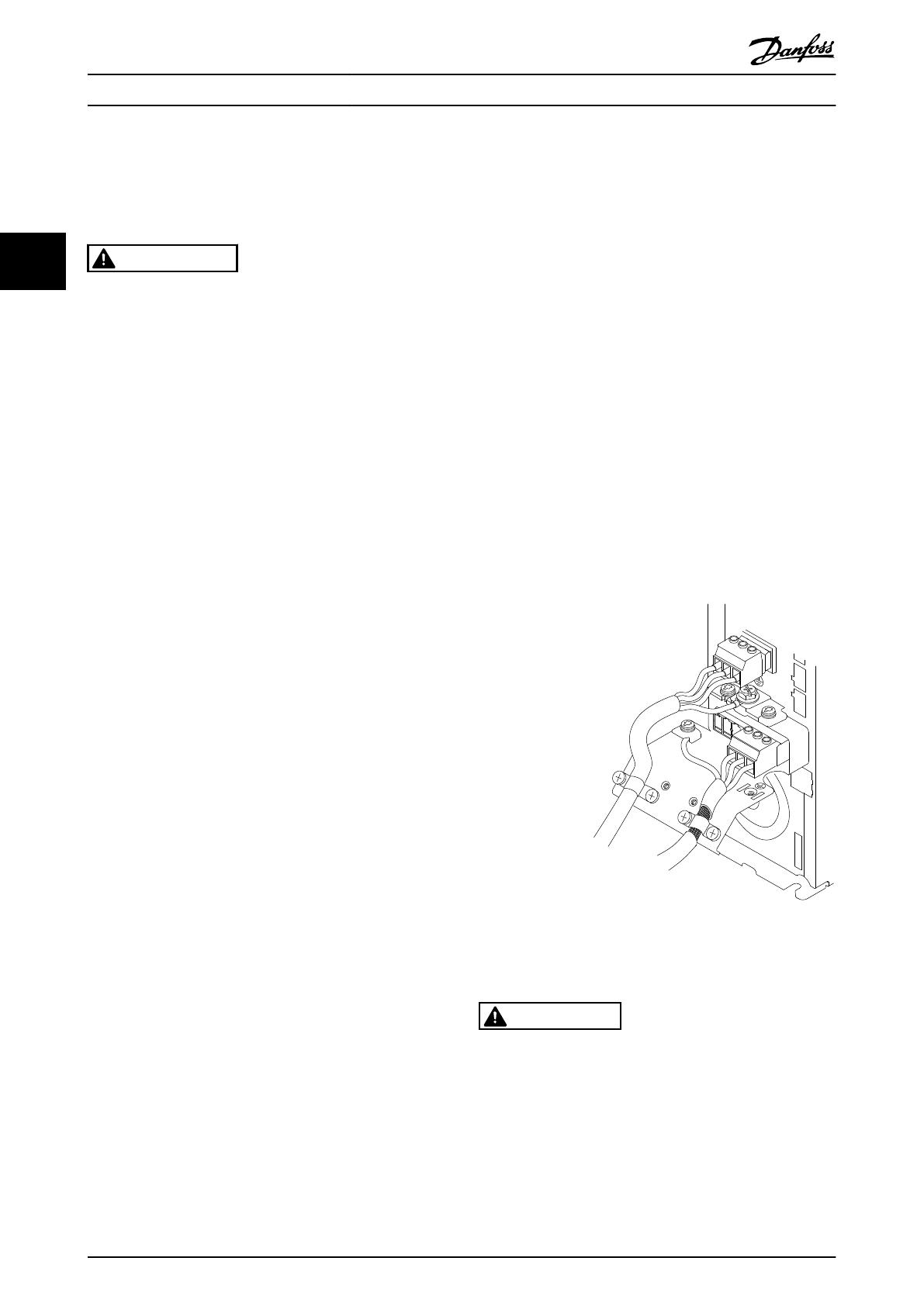
Grounding Using Shielded Cable
Earthing (grounding) clamps are provided for motor wiring
(see Illustration 3.8).
130BA266.10
+DC
BR-
B
MAINS
L1 L2 L3
91 92 93
RELAY 1 RELAY 2
99
- LC -
UVW
MOTOR
Illustration 3.8 Grounding with Shielded Cable
3.4.3
Access
CAUTION
Device damage through contamination
Do not leave the frequency converter unconvered.
•
Remove access cover plate with a screw driver.
See Illustration 3.9.
•
Or remove front cover by loosening attaching
screws. See Illustration 3.10.
Installation VLT® Refrigeration Drive 1.1-90 kW Operating Instructions
14 MG16E102 - VLT® is a registered Danfoss trademark
3
3


