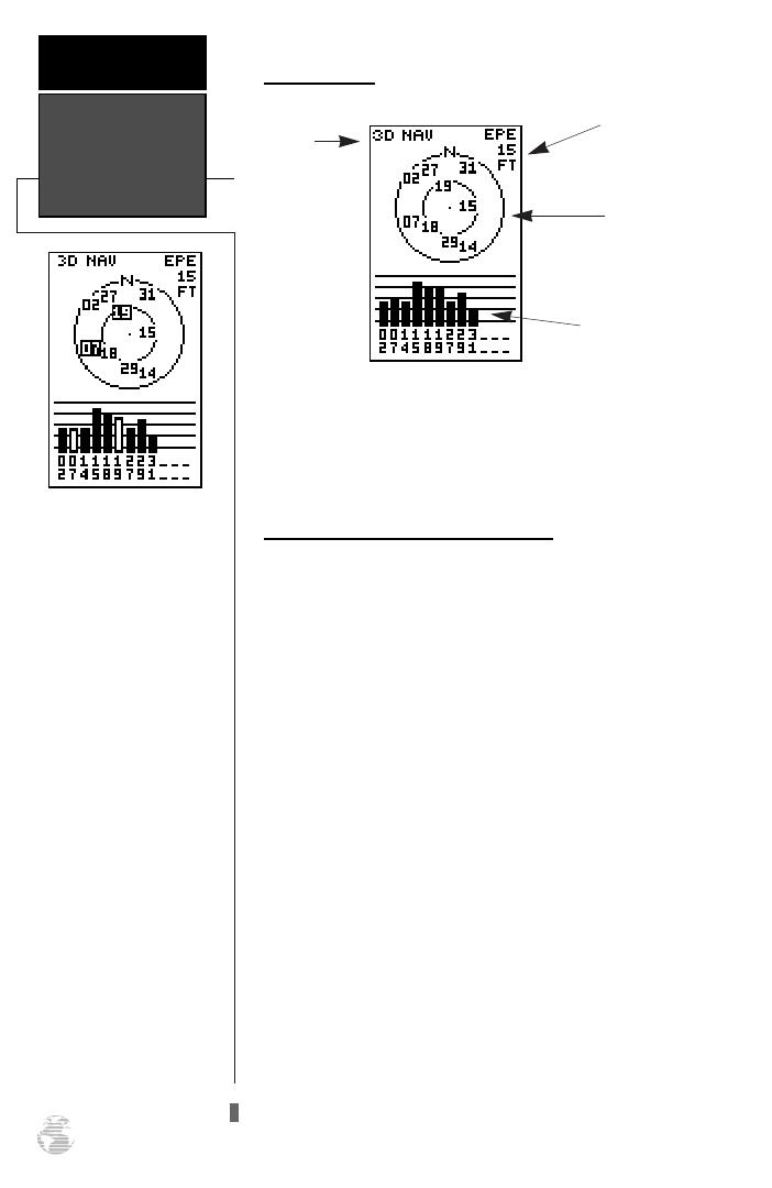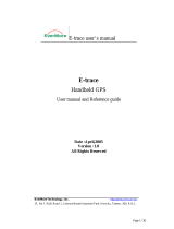
Receiver Status and EPE
Receiver status is indicated at the top left of the
page, with the current horizontal accuracy (EPE, esti-
mated position error, in feet or meters) at the top right.
The status will be shown as one of the following condi-
tions:
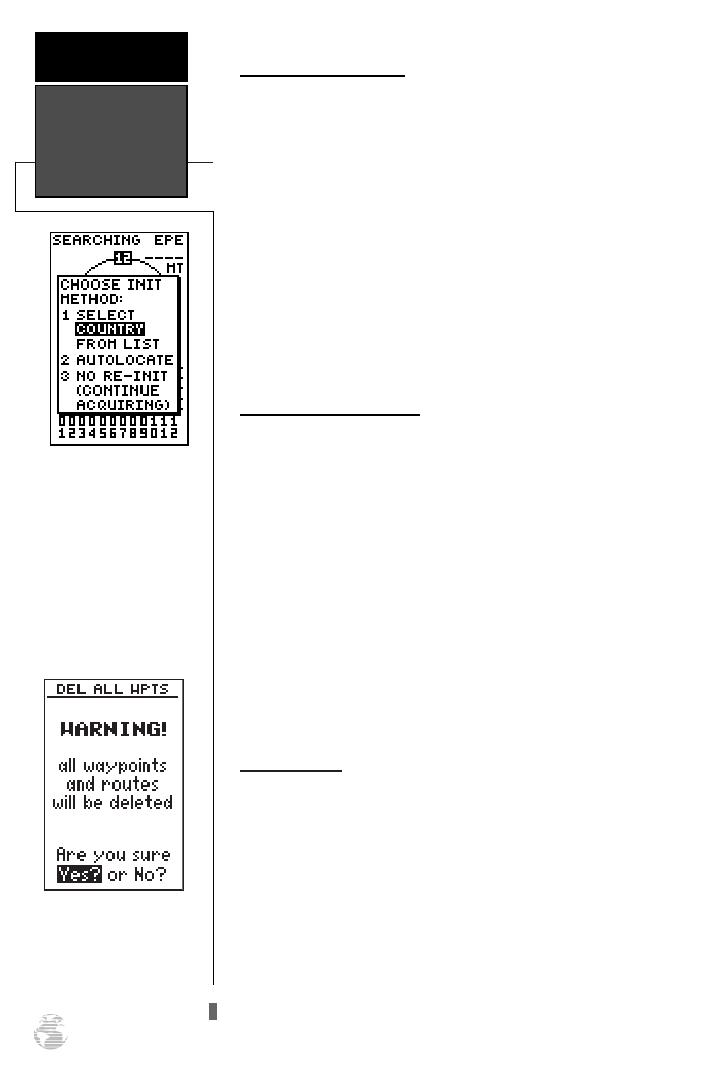
Searching—
the GPS 126/128 is looking for any
available satellites in view.
AutoLocate—
the GPS 126/128 is initializing and
collecting new almanac data. This process can take
5 minutes, depending on the satellites currently in
view.
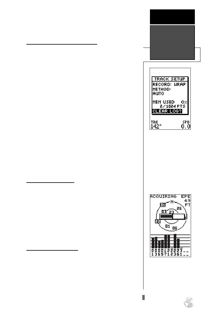
Acquiring—
the receiver is collecting data from
available satellites, but has not collected enough
data to calculate a 2D fix.
2D Navigation—
at least three satellites with
good geometry have been locked onto and a 2-
dimensional position fix (latitude and longitude) is
being calculated. ‘2D Diff’ will appear when you are
receiving DGPS corrections in 2D mode.
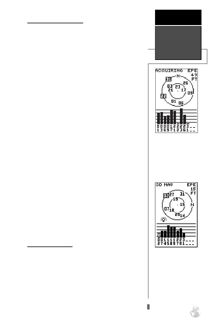
3D Navigation—
at least four satellites with good
geometry have been locked onto, and your position
is now being calculated in latitude, longitude and
altitude. ‘3D Diff’ will appear when you are receiving
DGPS corrections in 3D mode.
Poor GPS Coverage—
the receiver isn’t tracking
enough satellites for a 2D or 3D fix.
Not Usable—
the receiver is unusable, possibly
due to abnormal satellite conditions. Turn the unit
off and back on to reset, and reinitialize the receiv-
er if necessary.
Simulator—
the receiver is in simulator mode.
Screen Backlighting
The GPS 126/128 feature illuminates the screen
display for a user-defined interval (the default is 15 sec-
onds). There are three stages of backlighting. When
backlighting is on, a bulb icon will appear at the bot-
tom left of the sky view. To adjust the duration of
screen backlighting, refer to the system setup section
(see page 47).
Note: A bulb icon will appear on the Satellite Page
when backlighting is on.
15
The signal strength bars at
the bottom of the page will
not appear until the GPS
126/128 has found the
satellites indicated at the
bottom of the screen.
REFERENCE
Receiver Status
& Screen
Backlighting
When backlighting is on, a
bulb icon will appear on
the Satellite Page.
Use the icon to determine
if backlighting is turned
on during daylight hours.
126/128 Manual (new) 6/15/98 9:51 AM Page 15