D-Link DIV-140 User manual
- Category
- Gateways/controllers
- Type
- User manual


D-Link DIV-140 User Guide 2
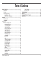
Table of Contents
Product Overview .......................................................................3
Introduction .........................................................................3
Features .............................................................................4
Hardware Overview ............................................................5
Front Panel - LEDs ........................................................5
Rear Panel - Connections .............................................6
Installation ...................................................................................7
Requirements .....................................................................7
Connection .........................................................................8
Configuration ..............................................................................9
Web-based Configuration .................................................10
Device Configuration ...................................................12
Audio Configuration .....................................................13
Call Configuration ........................................................15
Network Configuration .................................................17
Time Configuration ......................................................18
NAT Configuration .......................................................19
Media Configuration ....................................................20
VoIP Configuration ......................................................21
Hunt Group ..................................................................23
Destination ..................................................................24
ACR .............................................................................26
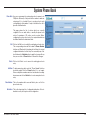
System Phone Book ....................................................28
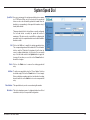
System Speed Dial ......................................................29
Port Configuration .......................................................30
Port Phone Book .........................................................32
Port Speed Dial ...........................................................33
Login Configuration .....................................................34
Debug ..........................................................................35
Device Management ...................................................36
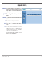
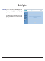
Upgrade History ..........................................................37
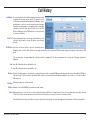
Call History ..................................................................38
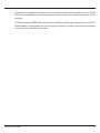
Port Status ..................................................................40
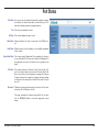
Save Changes .............................................................. 41
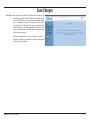
Restart System............................................................. 42
Troubleshooting ......................................................................... 43
Warranty ..................................................................................... 48
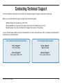
Contacting Technical Support .................................................. 52
Registration ................................................................................ 53

D-Link DIV-140 User Guide 3
Introduction
Product Overview
The D-Link Analog Trunk Gateway DIV-140 is a full featured multi port SIP based VoIP gateway. It links traditional telephone network and
IP network. Using the DIV-140 you can explore the wide features of VoIP technology. It enables you to make and receive calls through a
low cost VoIP network using a conventional telephone network setup.
The advanced technology behind the DIV-140 presents a highly scalable and flexible architecture to cater to the needs of varied market
segments.
The highly flexible call routing settings allow the administrator to configure different routes for calls based on the dialed number. It provides
configuration to route all local PSTN numbers through PSTN lines and all long distance calls through different VoIP networks. Both, proxy
based calls and peer to peer calls, are supported simultaneously. It supports per port phone book and system phone book to place peer
to peer calls without going through a VoIP server.
It supports per port speed dial lists and system speed dial lists to enable quick dialing to frequently accessed numbers. Also various call
features can be individually configured for each port to different destinations.
With support to configure IP settings manually or use DHCP or PPPoE, the DIV-140 can work in different environments. Also, NTP is
supported with standard time zone configuration to keep the device time in sync with a server.
In VoIP server mode, each port can be configured with different account or the feature can be enabled to use same account for all ports.
With backup server configuration support, the device can still work in absence of primary server. The support for STUN and IP Sharing
enables the device to work behind NAT.
It provides secure web based management interface with administrative and restricted accesses to remotely configure and monitor the
system. The configuration backup facility helps in maintaining multiple configurations for the device.

D-Link DIV-140 User Guide 4
Following features are supported.
Protocols
• SIP RFC 3261 Compliance
• STUN and IP sharing support for NAT
• RTP and RTCP
• DTMF Tx/Rx support using SIP INFO or Out of Band as per
RFC 2833.
• Fax Support using T.38 Fax Relay and Fax Passthrough
• NTP to keep device time in synchronization
• DNS/SRV RFC 3263 compliance
Features
• DTMF generation and detection
• Fax-tone detection
• Caller ID Detection and Generation
• Custom Caller ID Configuration
• Detection and generation of user-specified tones
• Polarity Reversal Generation
Call Features
• Consultation Call Hold
• Attended and Unattended Call Transfer
• Call Forward (Always, on Busy, on No Answer)
• Call Waiting
• Hot line and Warm line
• ACR
• Hunt Group
• Speed Dial (System wide and per port)
• Phone Book (System wide and per port)
Features
Audio Features
• G.729ab — G.729a with VAD and CNG support
• G.711 µ-law and A-law codec
• G.711 Annex 2. Support for VAD and CNG
• G.723.1 with 5.3 and 6.3 Kbps rates
Voice Quality
• IP layer TOS
• Dynamic/Adaptive Jitter Buffer algorithm
• Packet loss concealment (PLC)
• Echo Cancellation (G.168)
• Gain/Attenuation settings
Miscellaneous
• Forced Call disconnection from WEB/CLI/by dialing in key
sequence
• Upgrade History, Call History, Port Statistics Display
• HTTP/TFTP software upgrade
• Configuration Backup and Restore.
• Syslog Support
• Restore to Factory Default

D-Link DIV-140 User Guide 5
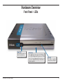
Hardware Overview
Front Panel - LEDs
Power LED
Will illuminate when the
device is powered on.
PSTN LEDs
These LEDs show the status of the FXO ports.
If an LED is illuminated, the phone is off the
hook, if it is not illuminated, the phone is on
the hook. It will blink during a conversation or
firmware upgrade.
LAN LED
Will blink to indicate
activity on the LAN port.

D-Link DIV-140 User Guide 6
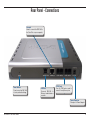
Rear Panel - Connections
LAN Port
Connects DIV-140 to
Ethernet enabled device
or switch.
Power Receptor
Receptor for Power Adapter.
Console
Used to connect the DIV-140 to
the Com Port on your computer.
PSTN Ports
Four (4) FXO ports used to
connect to wall phone jacks.
Reset Button
Press to reset the DIV-140
to factory default settings.

D-Link DIV-140 User Guide 7
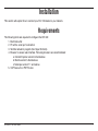
Installation
The following items are required to configure the DIV-140:
1. Electrical outlet
2. PC with a serial port connection
3. Terminal emulator program (like Hyper Terminal)
4. Browser to access web interface. Following browsers are recommended:
a. Internet Explorer version 6.0 and above
b. Mozilla version 5.0 and above
c. Netscape version 7.1 and above
5. VoIP Accounts or PSTN Lines
Requirements
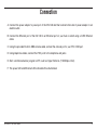
This section will explain how to connect your DIV-140 device to your network.

D-Link DIV-140 User Guide 8
A. Connect the power adaptor to power port of the DIV-140 and then connect other end of power adaptor to an
electric outlet.
B. Connect the Ethernet port of the DIV-140 to an Ethernet port on your hub or switch using a CAT5 Ethernet
cable.
C. Using the provided RJ-45 to DB9 console cable, connect the console port to your PC’s COM port.
D. Using telephone cables, connect the FXO ports to the telephone wall jacks.
E. Start a terminal emulator program on PC, such as Hyper Terminal. (115200 bps, 8 bit).
F. The power LED and Ethernet LEDs should both be illuminated.
Connection

D-Link DIV-140 User Guide 9
Configuration
Once powered on, the DIV-140 will be at its default configuration parameters. The default IP address of the device is 10.0.0.1. You can
configure the device either through the web UI or Command Line Interface (CLI).
In order to use a web browser to configure the device, you must make sure the device has a valid Ethernet connection to a PC or LAN via
its Ethernet port. We recommend using a recent version of the above mentioned browsers. The browser must have JavaScript enabled.
You must make sure the PC is in the same IP subnet as this device (10.0.0.1). You can do this by changing the IP address of the PC.
Type https://10.0.0.1 in the web browser address bar to access the web UI. Login with default user name and password as admin and
password. Refer to the “Web Configuration” section of this manual or online help for further details.
The network related parameters can also be configured through the CLI. Using a terminal emulator on your PC, you can modify these
parameters as per your network settings.
For examples and details of commands used here you can refer to CLI Commands section of this manual. Type question mark ‘?’ to see
the online help of command.
A. Enter user name as ‘admin’ and password as ‘password’.
B. Type ‘help’ to see the list of available commands.
C. Type ‘show nw’ to see the current network settings.
D. Change the IP mode using command ‘set nw mode’.
E. If IP mode is static IP use ‘set nw ip’ to set the new IP.
F. If IP mode is PPPoE use ‘set pppoe auth’ to set the user name and password.
G. Type ‘save’ to save the changes.
Now you can access the web interface of device using the new IP you have configured. Type https://<IPAddress> in your browser.

D-Link DIV-140 User Guide 10
Web-based Configuration
To use the web-based configuration utility you must use a computer either directly connected to the device using a cross-over Ethernet
cable or connected to the same network as the DIV-140. The default IP address is 10.0.0.1. If your network is using a different IP range,
you must first statically assign your computer an IP address of 10.0.0.2 (subnet mask - 255.0.0.0) and change the IP address of the
DIV-140 to an available IP address of your network.
To change your computer’s IP address, please refer to the Networking Basics section in this user guide.
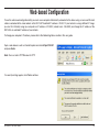
Open a web browser such as Internet Explorer and enter https://10.0.0.1
and press Enter.
Note: You must enter HTTPS instead of HTTP.
If a security warning appears, click Yes to continue.

D-Link DIV-140 User Guide 11
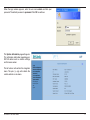
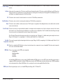
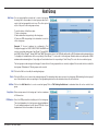
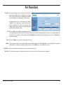
When the login window appears, enter the user name admin and then your
password. The default password is password. Click OK to continue.
The System Information page will appear.
This will display information regarding your
DIV-140 device such as network settings
and firmware version.
The left column will contain the navigation
menu. The plus (+) sign will indicate the
section contains a sub-menu.

D-Link DIV-140 User Guide 12
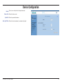
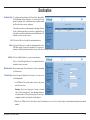
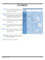
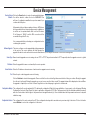
Device Configuration
Country:
Feature Code:
Speed Dial:
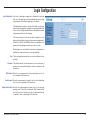
Auto Log Off Time:
Select your country from the drop-down menu.
Enter the feature code.
Enter the speed dial number.
Enter the time (in minutes) to automatically log off.

D-Link DIV-140 User Guide 13
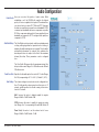
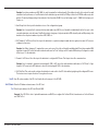
Audio Configuration
Codec Priority:
Jitter Buffer Delay:
Packet Loss Rate:
Gain Settings:
Here you can select the priority of audio codecs. While
establishing a call, the DlV-140 will negotiate the highest
priority of codec acceptable to both parties. The administrator
can choose from four codecs. G.711 Mu and G.711 A provide
the best voice quality but consume the most bandwidth. G.723
consumes less bandwidth with some compromise on quality.
G.729 is a compromise between both. It uses significantly less
bandwidth as compared to G.711 and gives better quality as
compared to G.723.
The Jitter Buffer monitors network conditions and implements
a delay profiling algorithm that provides better tracking of
adaptive jitter buffer and improves voice quality. The jitter buffer
automatically determines the network jitter, maintains the
desired packet loss rate, subject to the limit of the maximum
allowed jitter delay. These parameters can be configured
here.
The Jitter Buffer Delay specifies the maximum desired jitter
delay in milliseconds. Range: 0 to 500 milliseconds. Default:
150 milliseconds.
Specifies the allowable packet loss rate in 0.1% units. Range:
0 to 50 (corresponding to 0.1 % to 5.0 %). Default: 1 (0.1%).
The volume settings at various levels can be configured here.
Here Tx field specifies stream going from this device to IP
network and Rx specifies the stream coming to this device
from the IP network.
VoIP: Increase this value to digitally amplify the signals.
Range: -40 dB to 15 dB. Default: 0 dB.
PSTN: Increase this value to amplify the signals at analog
level. Range: 0 or 1 (corresponding to 0 and 6 dB). Default: 0.
Tone: Modify this value to set the volume level of tones.
Range: -20 dB to 15 dB. Default: -12 dB.

D-Link DIV-140 User Guide 14
In this mode of fax communication, G711 codec is used. Device will automatically switch to G711 codec on detection of FAX tone from the FAX
machine.
In this mode of fax communication, T.38 codec is used. Device will automatically switch to T.38 codec on detection FAX tone from the FAX machine.
If both the modes of fax communication are selected then preference will be given to Fax Relay mode. Following (FEC, Packet Redundancy Level,
and Ellipsis) are configurable parameters for Fax Relay features.
This feature can be selected to activate forward error correction in T.38 Fax Relay communication.
This feature can be selected to activate packet redundancy in T.38 Fax Relay communication.
This feature can be enabled to activate newer version of T.38 Fax protocol corrigendum 1. By enabling this feature, device will be able to work with
newer version fax devices.
The device cancels the echo generated by the hybrid of local telephone interface and phone set so that the other party connected to the channel
will not hear the echo. The parameters associated with echo cancellation can be configured here. Note: The default values should be good enough
for most cases and it is recommended that you don’t change it without assistance.
Echo Tail Length: This specifies the time span over which echo is expected to arrive. Tail length of 4 ~ 8 milliseconds is good enough for most cases.
Range: 2 to 64 in steps of 2 (corresponding to 1 to 32 milliseconds). Default: 36 (i.e. 18 milliseconds).
This is used to properly align the delayed signal with reference signal. Range: 0 to 240 (corresponding to 0 to 30 milliseconds). Default: 0 (i.e. 0
milliseconds).
When this is enabled, the DIV-140 detects a silence interval and uses silence compression to save on bandwidth. This feature works irrespective
of the codec selected. Default: Enabled.
There are four modes in which DTMF can be transmitted.
• In Band Mode
• Out Of Band Mode
• Info Mode
• Auto Mode.
In In Band Mode, DTMF packets are sent in band. In Out Of Band Mode, DTMF packets are sent as RTP Packets with different payload type as
configured in DTMF Payload field. In Info Mode, DTMF packets are sent as SIP INFO Packets and in Auto Mode the mode of DTMF transmission
is selected automatically to In Band, Out Of Band or Info according to the remote ends capability. Default: Auto Mode.
Enter the payload type to use for out of band DTMF packets. Range: 96 to 127. Default: 101.
Fax Pass Through:
Fax Relay:
FEC:
Packet Redundancy:
Elipsis:
Echo Tail Length:
Echo Delay
Compensation:
VAD:
DTMF Mode:
DTMF Pay Load:

D-Link DIV-140 User Guide 15
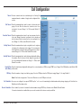
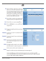
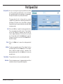
Call Configuration
Timeout:
Dial Timeout:
Connection Timeout:
Alerting Timeout:
Interdigit Timeout:
Interdigit Time
while Dialing:
FXO Rings:
Dial Termination:
Character Termination:
Various constants which are used during the call setup (like
maximum timeout or number of rings) can be configured in this
section.
Enter the maximum time to wait for a user to dial any key after
going off hook. After this timeout is reached an error tone
is played to the user. Range: 5 to 120 seconds. Default: 15
seconds.
Enter the maximum time to wait to get any response from the
other end. During this period a progress tone is played and
after the timeout limit is reached an error tone is played to the
user. Range: 5 to 180 seconds. Default: 45 seconds.
Enter the maximum time to play a ring back tone for outgoing
calls when the called party starts ringing. For incoming calls
this field defines how long the phone will ring when user doesn’t
answer. Range: 5 to 120 seconds. Default: 60 seconds.
Enter the maximum time to wait in between digits while dialing
the number. After this timeout, further digits are ignored and
the collected digits will be dialed out. Range: 1 to 120 seconds.
Default: 5 seconds.
Enter the time between digits while dialing out the received number on FXO line using DTMF tones. Range: 50 to 1000 milliseconds. Default: 300
milliseconds.
Enter the number of rings to wait before going off hook on FXO port when the FXO port is ringing. Range: 1 to 9 rings. Default: 2.
Note: If this field is configured as 1 then caller ID detection on the FXO port won’t work.
Here you can configure if any special DTMF key like * or # to use for terminating the dialed number while placing outgoing call. Note that Inter
Digit timeout will be always active.
Select enable if you want to terminate the dialed number using a DTMF key, otherwise select Disable. Default: Enable.
If character termination is enabled then you can also terminate the feature access keys with this.

D-Link DIV-140 User Guide 16
Character:
Default Route:
Route all calls to
VoIP Server:
For example, the feature key sequence to initiate call hold feature is *111. If character termination is enabled to # then you can dial *111# for the
same.
Enter the character to use for termination. Range: 0 to 9, * or #. Default: #
Here you can configure how calls should be routed.
Enable this if all calls including calls to local FXO ports should be routed to the VoIP server. Default: Enable.
Note: If this field is enabled, then the calls to local FXO ports will fail if the VoIP server is not available.

D-Link DIV-140 User Guide 17
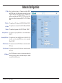
Network Configuration
IP Mode:
IP Address:
Net Mask:
Gateway:
Primary DNS Server:
Secondary DNS Server:
PPPoE Username:
PPPoE Password:
Idle Timeout:
Select a method to obtain an IP address from Static, DHCP
and PPPoE option. If the Static option is selected, then a user
configured IP address, Net Mask, gateway and DNS server
addresses would be used. If DHCP or PPPoE is selected, then
these values will be obtained using DHCP or PPPoE. Default:
Static.
This specifies the IP address of the DIV-140. Default: 10.0.0.1
This specifies the net mask of the DIV-140. Default: 255.0.0.0
This specifies the gateway of the DIV-140. Default: 10.0.0.1
This specifies the primary DNS Server of the DIV-140. Default:
10.0.0.1
This specifies the back up DNS Server of the DIV-140. This
is used in case the primary DNS server is not responding.
Default: 10.0.0.1
This username is used in PPPoE mode to authenticate with a
PPP server.
This password is used in PPPoE mode to authenticate with a
PPP server.
If the PPPoE session is inactive for the time specified in this
field then the session will be terminated. Range: 0 to 86400
seconds. Default: 900 seconds.

D-Link DIV-140 User Guide 18
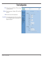
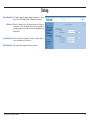
Time Configuration
Mode:
NTP Server:
GMT:
Date and Time:
The time can be set to either Manual or NTP by selecting the
corresponding radio button.
Enter the domain name or IP address of NTP server. Default:
pool.ntp.org.
Select the time zone from the drop-down menu.
In manual mode the device date and time can be configured
here in YYYY-MM-DD Hrs:Min:Sec (Year-Month-Date Hours:
Minutes:Seconds) format.

D-Link DIV-140 User Guide 19
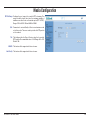
NAT Configuration
IP Sharing:
Global IP Address:
Stun:
Primary Server:
Port:
Secondary Server:
Port:
Username:
Password:
TURN Configuration:
For the device to work behind NAT enable IP Sharing, STUN or
TURN. IP Sharing is simplest and can be used in the scenario
where on the network router, one to one static address mapping
can be configured.
Configure here the global or external IP address of the
network. Contact your system administrator to get the global
IP address.
Note: The router should be statically configured for one to one
port mapping of ports in the RTP port range configured on
the Network Configuration > Media page and the VoIP Local
port configured on the VoIP Configuration page.
Enable this to use STUN for resolving the bindings.
Enter the IP address of the primary STUN server.
Enter the primary STUN server port in this field.
Default: 3478.
Enter the IP address of secondary STUN server.
Enter the secondary STUN server port in this field.
Default: 3478.
This specifies the username to use for authentication with a
STUN server.
This specifies the password to use for authentication with a
STUN server.
Note: When STUN is enabled the Registration Timeout option
on the VoIP Configuration page should be set to a value
smaller than the binding inactivity timeout on the NAT/Router.
This way the binding for the SIP local port can be kept alive.
This feature will be supported in future release.

D-Link DIV-140 User Guide 20
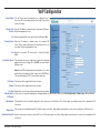
Media Configuration
RTP Port Range:
QoS:
ToS:
VLAN ID:
User Priority:
Configure the port range to be used for RTP streaming. This
range should be larger than twice the maximum number of
simultaneous calls as each call needs two ports (RTP + RTCP).
Range: 1024 to 65535. Default: 6000 to 10000.
Parameters for various Quality-of-Service mechanisms can be
set in this section. These are used to prioritize the RTP packets
on the network.
This field specifies the Type-of-Service value that is used for
RTP packets. Recommended value is 160. Range: 00 to 255.
Default: 160.
This feature will be supported in future releases.
This feature will be supported in future releases.
Page is loading ...
Page is loading ...
Page is loading ...
Page is loading ...
Page is loading ...
Page is loading ...
Page is loading ...
Page is loading ...
Page is loading ...
Page is loading ...
Page is loading ...
Page is loading ...
Page is loading ...
Page is loading ...
Page is loading ...
Page is loading ...
Page is loading ...
Page is loading ...
Page is loading ...
Page is loading ...
Page is loading ...
Page is loading ...
Page is loading ...
Page is loading ...
Page is loading ...
Page is loading ...
Page is loading ...
Page is loading ...
Page is loading ...
Page is loading ...
Page is loading ...
Page is loading ...
Page is loading ...
-
 1
1
-
 2
2
-
 3
3
-
 4
4
-
 5
5
-
 6
6
-
 7
7
-
 8
8
-
 9
9
-
 10
10
-
 11
11
-
 12
12
-
 13
13
-
 14
14
-
 15
15
-
 16
16
-
 17
17
-
 18
18
-
 19
19
-
 20
20
-
 21
21
-
 22
22
-
 23
23
-
 24
24
-
 25
25
-
 26
26
-
 27
27
-
 28
28
-
 29
29
-
 30
30
-
 31
31
-
 32
32
-
 33
33
-
 34
34
-
 35
35
-
 36
36
-
 37
37
-
 38
38
-
 39
39
-
 40
40
-
 41
41
-
 42
42
-
 43
43
-
 44
44
-
 45
45
-
 46
46
-
 47
47
-
 48
48
-
 49
49
-
 50
50
-
 51
51
-
 52
52
-
 53
53


D-Link DIV-140 User manual
- Category
- Gateways/controllers
- Type
- User manual
Ask a question and I''ll find the answer in the document
Finding information in a document is now easier with AI
Related papers
Other documents
-
Dlink DIV-140 Owner's manual
-
Cisco SPA8000 User manual
-
3com VCX V7111 User manual
-
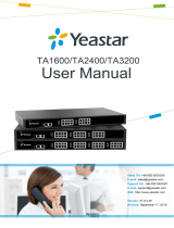 Yeastar TA1600/TA2400/3200 V3 User manual
-
 Yeastar NeoGate TA400 User manual
-
 Yeastar TA1600/TA2400/3200 User manual
-
Grandstream Networks GXW4224 User manual
-
-
Netcomm Gateway Series User manual
-
Grandstream GXW4200 Series User manual


