
Instructions for Installation and Use
Electric Hood
Model HDI90X

GB 2
CONTENTS
RECOMMENDATIONS AND SUGGESTIONS 3
INSTALLATION 4 - 9
ELECTRICAL CONNECTION 10
GETTING TO KNOW YOUR COOKER HOOD 11
CARE AND CLEANING 12
AFTER SALES SERVICE 14
GUARANTEE 15
KEY CONTACTS Back Cover
Retention of this Instruction Book
This Instruction Book must be kept handy for reference as it contains important details on the safe and proper use
of the appliance.
If you sell or pass the appliance to someone else, or move house and leave it behind, make sure this Book is
also provided so the new owner can become familiar with the appliance and safety warnings.
If the Book is lost or damaged a copy may be obtained from:
GDA LTD., Morley Way, Peterborough, PE2 9JB
CE marking certifies that this appliance conforms to the
following EEC directives:-
- Low Voltage Equipment 72/23/EEC
- Electromagnetic Compatibility 89/336/EEC

3GB
RECOMMENDATIONS AND SUGGESTIONS
Using your new Cooker Hood is very simple. Nevertheless, to get the best results it is important
that you read this manual thoroughly before installing and using your appliance for the first time.
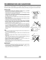
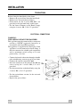
INSTALLATION
• All installation and repairs should be carried out by a qualified
technician in accordance to regulations in force.
• The manufacturer will not be held liable for any damage resulting
from incorrect or improper installation.
• After having removed the packaging, check the condition of the
appliance, if in any doubt, do not use and contact Hotpoint Service
(see Key Contacts, back page).
• The minimum safety distance between the hob and the extractor
hood is 650 mm.
• Check that the mains voltage corresponds to that indicated on the
rating plate fixed to the inside of the hood.
• Connect the extractor to the exhaust flue through a pipe of minimum
diameter 120 mm. The route of the flue must be as short as possible.
• Do not connect the extractor hood to exhaust ducts carrying
combustion fumes (boilers, fireplaces, etc.).
• If the extractor is used in conjunction with non-electrical appliances
(e.g. gas burning appliances), a sufficient degree of ventilation
must be guaranteed in the room in order to prevent the backflow of
exhaust gas. The kitchen must have a suitable vent to the outside
of the building, so that clear fresh air can circulate through the
kitchen.
USE
• The extractor hood has been designed exclusively for domestic use
to eliminate kitchen smells.
• Never use the hood for purposes other than for which it has been
designed.
• Never leave high naked flames under the hood when it is in
operation.
• Adjust the flame intensity to direct it onto the bottom of the pan
only, making sure that it does not engulf the sides.
• Deep fat fryers must be continuously monitored during use:
overheated oil can burst into flames.
• When frying, never leave the pan unattended.
• The hood should not be used by children or persons not instructed
in its correct use.
MAINTENANCE
• Switch off and unplug the appliance from the mains supply before
carrying out any cleaning or maintenance work.
• Clean regularly (see Care and Cleaning section), build up of dirt
and grease could cause a fire hazard.

4GB
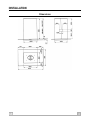
INSTALLATION
Dimensions

5GB
INSTALLATION
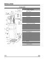
Components
Ref. Qty Product Components
1 1 Hood Body, complete with: Controls, Light,
Blower, Filters
2 1 Telescopic Chimney comprising:
2.1 1 Upper Section
2.2 1 Lower Section
7.1 1 Telescopic frame complete with extractor,
consisting of:
7.1a 1 Upper Frame
7.1b 1 Lower Frame
8a 1 Right Air Outlet Grill
8b 1 Left Air Outlet Grill
9 1 Reducer Flange ø 150-120 mm
14 1 Hood Body Air Outlet Extension Piece
consisting of two half shells
14.1 1 Air Outlet Connection Extension
15 1 Air Outlet Connection
24 1 Junction box
25 2 Pipe clamps
26 1 Fixing part of the upper chimney
Ref Qty Installation Components
11 4 Wall Plugs ø 10
12c 6 Screws 2.9 x 9.5
12e 2 Screws 2.9 x 6.5
12f 4 Screws M6 x 10
12g 4 Screws M6 x 80
12h 4 Screws 5.2 x 70
12w 2 Screws M3 x 8
21 1 Drilling Template
22 4 6.4mm int. dia washers
23 4 M6 nuts
Qty Documentation
1 Instruction Manual

6GB
INSTALLATION
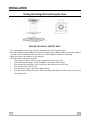
Drilling the Ceiling/shelf and fixing the frame
DRILLING THE CEILING / SUPPORT SHELF
• Use a plumb line to mark the centre of the hob on the ceiling/support shelf.
• Place the drilling template 21 provided on the ceiling/support shelf, making sure that the template
is in the correct position by lining up the axes of the template with those of the hob.
• Mark the centres of the holes in the template.
• Drill the holes at the points marked:
• For concrete ceilings, drill for plugs appropriate to the screw size.
• For hollow brick ceilings with wall thickness of 20mm: drill ø 10mm.
• For wooden beam ceilings, drill according to the wood screws to be used.
• For wooden shelf, drill ø 7mm.
• For the power supply cable feed, drill ø 10mm.
• For the air outlet (Ducted version), drill according to the diameter of the external air exhaust
duct connection.

7GB
INSTALLATION
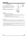
FIXING THE FRAME
Before fixing, seperate the Upper section 2.1 and
the Lower section 2.2 from the frame by unscrewing
the screws 12c. Then seperate the two sections of
the frame (Upper and Lower) by unscrewing the 8
side screws.
Fix the Fixing Part of the Upper Chimney 26 to the
hanging kit using the 2 screws 12w (M3 x 8).
Upper Frame
• Align the power supply cable feed hole.
• Fix the upper frame to the ceiling of shelf using:
• For concrete ceilings, use the appropriate plugs for the screw size (not provided).
• For hollow brick ceilings of wall thickness of approximately 20mm: use 4 plugs 11 and 4
screws 12h (5.2 x 70), provided.
• For wooden beam ceilings, use 4 wood srews (not provided).
• For wooden shelf, use 4 screws 12g (M6 x 80) with washers 22 and nuts 23, provided.
Lower Frame
• Fix the lower frame using the 8 previously removed screws, adjusting the length according to the
installation height (hood body lower fixing surface must be at least 710mm from the hob).
• For the recirculation version, turn the frame in the direction chosen for the recirculated air outlet.
• The frame mounting must be secure to withstand the weight of the hood and any stresses caused
by the occassional side thrust applied to the device. On completion, check that the base is stable,
even if the frame is subjected to bending.
• In all cases where the ceiling is not strong enough at the suspension point, the installer must
provide strengthening, using suitable plates and backing pieces anchored to the structurally sound
parts.

8GB
INSTALLATION
Connections
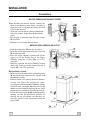
DUCTED VERSION AIR EXHAUST SYSTEM
When installing the ducted version, connect the
hood to the chimney using either a flexible or
rigid pipe ø 150 or 120 mm, the choice of which
is left to the installer.
• To install a ø 120 mm air exhaust connection,
insert the reducer flange 9 on the hood body
outlet.
• Fix the pipe in position using the pipe clamps
25 provided.
• Remove any activated charcoal filters.
RECIRCULATION VERSION AIR OUTLET
• Push the connection 15 onto the air outlet.
• Insert the connection extension pieces laterally
14 in connection 15.
• Place the upper chimney section and fix the
upper part to the Fixing Part of the Upper
Chimney using the 2 screws 12c (2.9 x 9.5)
provided.
• Similarly, position the lower chimney section
and fix the lower part to the frame using the 2
screws 12c (2.9 x 9.5) provided.
Recirculation version
• Make sure that the outlet of the extension pieces
14.1 is horizontally and vertically aligned with
the chimney outlets.
• If this is not the case, remove the lower chimney
section and adjust the position by either
reversing the connection pieces 14.1 or by cutting
the hood body extension 14 along one of the
thinner section channels denoting the pre-fixed
lengths, then reassemble as described previously.
• Fit the directional grids 8a-8b in their housings
making sure that the directional symbols are
towards the top. Also make sure that they are
correctly inserted in the connection extension
pieces 14.1.

9GB
INSTALLATION
Connections
Before fixing the hood body to the frame:
• Remove the grease filters from the hood body.
• Remove any activated charcoal filters.
• From below, use the 4 screws 12f (M6 x 10)
provided, to fix the hood body to the frame.
• Fix the Lower Chimney to the Hood Canopy
using the 2 screws 12c (2.9 x 9.5) provided.
ELECTRICAL CONNECTIONS
WARNING -
THIS APPLIANCE MUST BE EARTHED
This appliance must be connected by a competent
person eg. NICEIC registered contractor, in
accordance with latest IEE regulations.
The appliance is supplied with a fitted plug. If the
appliance is to be connected to fixed wiring, it
must be connected to a double-pole control unit
with a minimum switch rating of 5A and
protected by a 3A fuse.
• Connect the hood to the mains through a double
pole switch having a contact gap of at least 3mm.
• Connect the control connector Cmd.
• Place the connector in the junction box 24 and
close it using the 2 screws 12e (2.9 x 6.5)
provided.
• Fix the junction box to the hood body using the
2 screws 12c (2.9 x 9.5) provided.
• For the recirculation version, fit the activated
charcoal filter.
• Replace the grease filters.

10GB
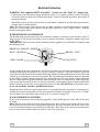
Electrical Connection
WARNING: This appliance MUST be earthed. Connect to a 230 - 240V A.C. Supply only.
• Connection to the electricity supply should be made via a properly earthed, readily accessible
wall socket which is adjacent to and not more than 1.25m away from the appliance and capable of
electrical isolation.
Should this plug not fit the socket outlet in your home it should be cut off and replaced with a
suitable plug as outlined below.
Note: The removed plug cannot be used for any other appliance and should therefore be properly
disposed of and not left where children might find it and plug it into a supply socket - with the
obvious consequent danger.
IF THE FITTED PLUG IS REMOVED
The flexible mains lead must be correctly connected as below, to a three pin plug of not less than 13
amp capacity. If a B.S.1363 fused plug is used, it must be fitted with a 3amp fuse which is approved
to B.S.1362.
IMPORTANT: The wires in the mains lead fitted to this appliance are coloured in accordance with
the following code:
GREEN and YELLOW - EARTH
BLUE - NEUTRAL BROWN - LIVE
CORD CLAMP 3amp FUSE
As the colours of the wires in the mains lead of this appliance may not correspond with the coloured
markings identifying the terminals in your plug, proceed as follows:- The wire which is green and
yellow must be connected to the terminal in the plug which is marked with the letter E or by the earth
symbol or coloured green or green and yellow. The wire which is coloured blue must be connected
to the terminal which is marked with the N or coloured black. The wire which is coloured brown
must be connected to the terminal which is marked with the letter L or coloured red. When wiring the
plug, ensure that all strands of wire are securely retained in each terminal. Do not forget to tighten the
mains lead clamp on the plug. As the appliance must be earthed, DO NOT use 2-pin socket outlets,
if you are in doubt, consult a qualified electrician.
Should the mains lead ever require replacement, it is essential that this operation be carried out by a
qualified electrician and should only be replaced with a flexible cord of the same size ie. 0.75mm
2
cross sectional area and temperature rating of 85°C eg. heat resisting PVC.
IF A MOULDED PLUG IS FITTED
In the event of replacing a fuse in the plug supplied a 3amp ASTA approved fuse to B.S.1362 must
be fitted.
Note: The fuse cover must be refitted when changing the fuse. In the event of losing the fuse cover
the plug must not be used until a replacement fuse cover has been obtained and fitted. A new fuse
cover can be obtained from your local Electrical Retailer. The colour of the correct replacement fuse
cover is that of the coloured marks or inserts in the base of the plug.

11GB
GETTING TO KNOW YOUR COOKER HOOD
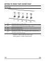
The Controls
WARNING: Children should not be allowed to play
with the appliance or tamper with the controls.
L Light Switches the lighting system on and off.
V1 Motor Switches the extractor motor off and on at low speed. Used to provide a continuous
and silent air change in the presence of light cooking vapours.
V2 Speed Reduces the operating speed.
V3 Speed Increases the operating speed.
V4 Intensive Maximum speed, used to eliminate the highest cooking vapour emission.
Speed Switches off automatically after 10 minutes operation. Can also be switched
off manually by pressing the button.

12GB
CARE AND CLEANING
Before cleaning your cooker hood or carry out any
maintenance, switch off and remove the plug from
the socket to disconnect it from the electricity
supply.
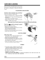
CLEANING METAL GREASE FILTERS
The filters must be cleaned every 2 months of
operation, or more frequently with heavy usage,
and can be washed in a dishwasher.
• Remove the filters one at a time by pushing
them towards the back and pulling down at the
same time.
• Wash the filters, taking care not to bend them.
Allow them to dry before refitting.
• When refitting the filters, make sure that the
handle is visible on the outside.
REPLACING THE ACTIVATED CHARCOAL FILTER (RECIRCULATION VERSION)
The filter is
not washable and must be replaced
after every 4 months of operation, or more
frequently with heavy usage.
• Remove the metal grease filters.
• Remove the saturated activated charcoal filter
by releasing the fixing hooks.
• Dispose of the charcoal filter.
• Fit the new filter by hooking it into its housing.
• Replace the metal grease filters.
LIGHT REPLACEMENT
20W halogen light
• Remove the 2 screws fixing the Lighting support,
and pull it out away from the hood.
• Extract the lamp from the support.
• Replace with another of the same type, making
sure that the two pins are properly inserted in
the lamp holder socket holes.
• Replace the support and fix it in place with the
teo screws previously removed (above).
CLEANING
• Clean with a sponge soaked in warm water and
a sodium bicarbonate solution, which is among
other things a good disinfectant. If you do not
have any, you can use a neutral soap.
• DO NOT use abrasive detergents, bleach or
detergents using ammonia.
• NEVER use solvent based products.
Failure to carry out the basic standards of cleaning and replacement of the filters could cause a fire
risk. Therefore you must observe these instructions.

13GB
NOTES

GB 14
"No company is better positioned to offer an after sales service on a
Hotpoint appliance than us - the manufacturer"
As part of our commitment to you, all Hotpoint appliances have the added benefit of a fully
inclusive parts and labour guarantee for the first 12 months. In addition to this you also have the
advantage of free replacement parts for the first 5 years when fitted by a Hotpoint
engineer. When the 12 months parts and labour guarantee expires we offer the following after
sales service options:
Repair Service and Information Help Desk
UK: 08709 066066
www.theservicecentre.co.uk
Republic of Ireland: 1850 302 200
Note: Our operators will require the Model number and the Serial number of your appliance
Available 364 days a year with a fast, effective and value for money service. We have the
largest white goods repair service in the UK with over 1200 of our own fully trained engineers.
All repairs include a parts and labour guarantee for 12 months from the date of the repair.
If you require any information or have any questions about your appliance, our operators are on
hand with help and advice.
All this ensures that you will receive the best available after sales service possible.
Extended Warranties
UK: 08709 088 088
www.theservicecentre.co.uk
Republic of Ireland: 1850 502 200
Whether you have just one or a number of Hotpoint appliances in your kitchen, we offer two
service cover plans to give you total peace of mind.
Repair Protection Plan - FREE service repairs for a single Hotpoint appliance during
the period of cover.
Kitchen Cover - FREE service repairs for all your Hotpoint appliances less
than 8 years old.
Genuine Parts and Accessories
UK: 08709 077 077
www.theservicecentre.co.uk
Republic of Ireland: (01) 842 6836
A wide range of genuine parts and accessories are available from our hotline or through our
website.
Genuine parts and accessories, extended warranties and service repairs are all
available on our web-site at:
www.theservicecentre.co.uk
After Sales Service

GB 15
Guarantee
"Satisfaction guaranteed or your money back"
We give you a unique 'satisfaction guaranteed' promise - valid for 90 days - after you have
purchased your Hotpoint appliance. If there is a technical problem simply call Hotpoint Repair
service or visit our web-site at www.theservicecentre.co.uk and where necessary, we will
arrange for an engineer to call. If the technical problem is not resolved under this guarantee,
we will replace your machine or, if you prefer, give you your money back.
All Hotpoint appliances carry a fully inclusive 12 month parts and labour guarantee as well as
free replacement parts for the first 5 years (except microwaves, selected integrated
appliances and cooker hoods, which have a one year guarantee) provided that they are fitted
by a Hotpoint engineer.
Guarantee terms and conditions
Your guarantee is only applicable in the United Kingdom or Republic of Ireland and is subject
to the following provisions that your appliance:
Has been installed and used correctly in accordance with this instruction booklet.
Has been used solely for domestic purposes and is located on domestic premises
(ie. not for commercial or trade use).
Has been properly connected to a suitable electrical supply voltage as stated on the
appliance rating plate.
Has not been subject to misuse, accident, modified or repaired by anyone other than
one of our own service engineers.
For pre purchase information on any other Hotpoint product call: 08701 50 60 70
or visit: www.hotpoint.co.uk
Recycling & Disposal Information
As part of Hotpoint's continued commitment to helping the environment, Hotpoint reserves
the right to use quality recycled components to keep down customer costs and minimise
material wastage.
Please dispose of packaging and old appliances carefully.
To minimise risk of injury to children, remove the plug and cut mains cable off flush with the
appliance. Dispose of these parts separately to ensure that the appliance can no longer be
plugged into a mains socket.

February 2003 Part no. FP175 - 01
Over 1200 trained specialists, directly employed by us, ensure that you can have complete
confidence in both the appliances and services we offer.
Repair Service and Information Desk
UK: 08709 066 066
(Open 8 to 8 Mon - Fri, 8 to 6 Sat, 10 to 4 Sun & Bank Holidays)
www.theservicecentre.co.uk
Republic of Ireland: 1850 302 200
Note: Our operators will require the following information:
Model number:
Serial number:
Extended Warranties
UK: 08709 088 088
(Open 8 to 8 Mon - Sun)
www.theservicecentre.co.uk
Republic of Ireland: 1850 502 200
Genuine Parts and Accessories
UK: 08709 077 077
(Open 8-30 to 5-30 Mon - Fri & 9 to 12 Sat)
www.theservicecentre.co.uk
Republic of Ireland: (01) 842 6836
General Domestic Appliances Limited, Morley Way, Peterborough, PE2 9JB.
Key Contacts
After Sales Service
-
 1
1
-
 2
2
-
 3
3
-
 4
4
-
 5
5
-
 6
6
-
 7
7
-
 8
8
-
 9
9
-
 10
10
-
 11
11
-
 12
12
-
 13
13
-
 14
14
-
 15
15
-
 16
16


Ask a question and I''ll find the answer in the document
Finding information in a document is now easier with AI
Related papers
-
Hotpoint HE91 User manual
-
-
-
-
-
-
Hotpoint F032592 User manual
-
-
-